4.12.1 Outlet Control Introduction
Outlet controls regulate the release of stormwater from a stormwater management practice (SMP). Proper design and construction practices are crucial to outlet control performance, which is closely interconnected with SMP performance. They must be appropriately selected and sized for the storage component of the SMP. Small differences in outlet control parameters, such as dimensions and invert elevations, can have drastic effects on SMP outflow characteristics. Examples of outlet controls include orifices, weirs, risers, underdrains, level spreaders, impervious liners, micro siphon drain belts, and low flow devices.
Outlet controls can provide a range of functions including:
- Meeting peak flow requirements;
- Controlling the rate of discharge from the SMP during various storm events;
- Controlling the amount of water stored for infiltration;
- Meeting drain down requirements;
- Providing adequate retention time for Water Quality requirement treatment;
- Bypassing of larger flows (positive overflow) to prevent re-suspension of sediment, hydraulic overload, or erosion of management practices; and/or
- Reducing downstream erosion potential.
Quick Tip
Required outlet control design and material standards are denoted in this Section by easy-to-reference numerals.
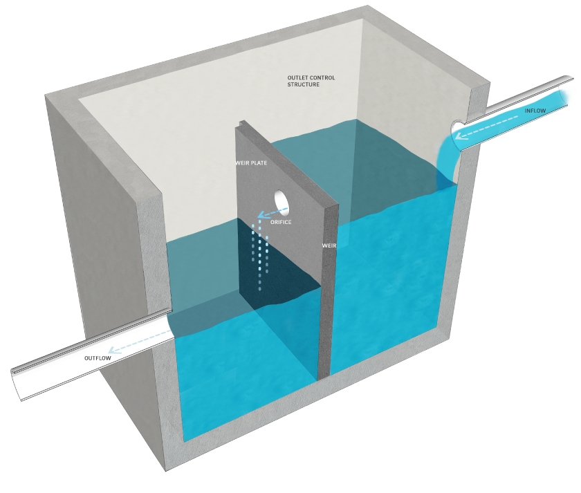
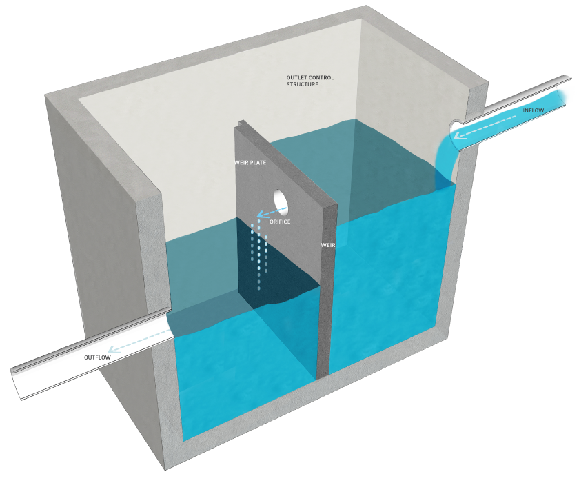
Outlet control structures typically consist of concrete boxes that contain one or more outlet controls such as orifices or weirs.
A multi-stage outlet control structure can be designed with multiple orifices and weirs at different elevations to meet varying Philadelphia Water Department (PWD) Stormwater Regulations (Stormwater Regulations). A multi-stage outlet control structure may include a number of orifices for controlled flow and a positive overflow to quickly pass flow during extreme events.
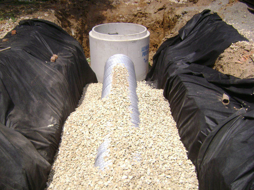
Design of outlet controls is not limited to the examples shown within this text. Successful stormwater management plans will combine appropriate materials and designs specific to each site.
The following table is a guide to the outlet controls covered in this Section showing whether or not they are typically used in conjunction with various SMP practices. Red indicates that an outlet control would typically be used with an SMP; yellow indicates that the outlet control may be used with the associated SMP in certain circumstances; and blue indicates that the outlet control would not typically be used with the associated SMP.
Table 4.12‑1: Outlet Controls Applicability Guidance
| SMP | Applicability | |||||||||||||||
|---|---|---|---|---|---|---|---|---|---|---|---|---|---|---|---|---|
| Orifices | Weirs | Risers | Underdrains | Level Spreaders | Impervious Liners | Micro Siphon Drain Belts | Low Flow Devices | |||||||||
| Ponds and Wet Basins | Typical | Typical | Typical | Unypical | Typical | Typical | Occasional | Occasional | ||||||||
| Bioretention | Typical | Typical | Typical | Typical | Typical | Occasional | Occasional | Occasional | ||||||||
| Bioinfiltration | Typical | Typical | Typical | Typical | Typical | Untypical | Untypical | Untypical | ||||||||
| Subsurface Detention | Typical | Typical | Untypical | Occasional | Tyipcal | Occasional | Occasional | Typical | ||||||||
| Subsurface Infiltration | Typical | Typical | Untypical | Occasional | Typical | Untypical | Untypical | Untypical | ||||||||
| Blue Roofs | Typical | Occasional | Occasional | Untypical | Untypical | Typical | Untypical | Occasional | ||||||||
| Media Filters | Occasional | Occasional | Untypical | Occasional | Occasional | Occasional | Occasional | Occasional | ||||||||
| Cisterns | Occasional | Occasional | Untypical | Untypical | Untypical | Occasional | Untypical | Occasional | ||||||||
| Green Roofs | Untypical | Untypical | Occasional | Untypical | Untypical | Typical | Occasional | Occasional | ||||||||
| Porous Pavement | Untypical | Untypical | Untypical | Occasional | Untypical | Untypical | Untypical | Untypical | ||||||||
General Design Standards
(Download Double Manhole Outlet Control Structure Standard Detail CAD File)
- Outlet controls must be provided as necessary to regulate flow in order to meet all applicable release rate, drain down time, ponding depth, positive overflow, and other requirements.
- Outlet controls must provide positive overflow for their associated SMP, allowing stormwater to flow out of the SMP when the water level reaches a maximum design elevation in a subsurface feature or a maximum ponding depth in a surface feature without surcharging the SMP. Positive overflow from an SMP can either flow to another SMP or to an approved point of discharge. Outlet control structures must be sized to convey at least the ten-year, 24-hour storm event without surcharging the structure. The outlet controls must be designed to convey flows from the SMP up to the 100-year, 24-hour storm event, or, if the project is exempt from Flood Control, the ten-year, 24-hour storm, without surcharging the SMP. If flow reaches the SMP via a flow splitter, this structure can provide the positive overflow. The designer is referred to the SMP Sections within this Chapter for SMP-specific design standards.
- Outlet controls must be located so as to be easily and readily accessible for maintenance purposes.
- All outlet control structures in combined sewer areas must include a sump and trap or sump and hood. The sump depth must be at least 15 inches below the bottom of the trap or at least 12 inches below the bottom of the hood, and the traps or hoods must be air-tight. The designer is referred to the City of Philadelphia Water Department Standards Details and Standard Specifications for Sewers and the Philadelphia Plumbing Code Section P-1001.7 for additional guidance.
- Ladder bars must be included within any outlet control structure.
- Any manholes between outlet structures and sewer connections in combined sewer areas must have sanitary, non-vented covers.
- Outlet control structures must have solid, non-grated, tops.
- The outlet pipe of an outlet control structure must have an invert at or below the invert of the inlet pipe(s). Setting the outlet pipe invert at a minimum of 7.5 inches below that of the inlet pipe(s) is recommended.
Outlet Control Construction Guidance
Proper installation of outlet controls is essential to long-term function. Outlet controls must be installed per the following construction sequence:
- Install all temporary erosion and sedimentation controls in the immediately adjacent work areas in accordance with the latest edition of the Pennsylvania Department of Environmental Protection (PA DEP) Erosion and Sediment Pollution Control Program Manual prior to construction.
- If excavation is required, clear the areas to be excavated of all vegetation. Remove all tree roots, rocks, and boulders in excavation areas.
- Excavate areas to desired elevation (if necessary).
- If using an underdrain, place filter fabric or pea gravel filter, then place the rock and set the underdrain according to the plans. Otherwise, prepare subgrade for outlet structures.
- Install outlet controls according to plans. Outlet controls must be constructed in accordance with manufacturer’s guidelines or the design professional’s guidance. Outlet controls must comply with all applicable American Society of Testing and Materials (ASTM) testing methods as required by PWD.
- Confirm invert elevations and dimensions of outlet controls prior to final backfill and compaction of surrounding areas.
- Backfill and compact areas around outlet controls. Ensure backfill is properly compacted in accordance with specifications.
- Once site vegetation is stabilized, remove erosion and sediment control measures.
Outlet Control Maintenance Guidance
General recommended maintenance activities for outlet controls are summarized in Table 4.12‑2.
Table 4.12‑2: Outlet Controls Maintenance Guidelines
| Ongoing Activity | Frequency |
|---|---|
| Inspect outlet control structures after several storms to ensure that they are functioning properly and that there are no erosion problems developing. | As Needed |
| Identify any sources of sediment contamination and control when in situ soil is exposed or erosion channels are present. | As Needed |
| Maintain and cut back vegetation directly surrounding outlet control structures if impairing function of SMP. | As Needed |
| Clean out leaves, trash, and debris, from all structures, such as grates and orifices (Note: consult with professional vacuum cleaning service if subsurface pipes, including underdrains, appear to be clogged). | As Needed |
| Inspect for sediment and debris build-up. Sediment build-up exceeding two inches in depth or that begins to constrict the flow path must be removed. | Quarterly |
| Maintain records of all inspections and maintenance activity. | Ongoing |
4.12.2 Orifices
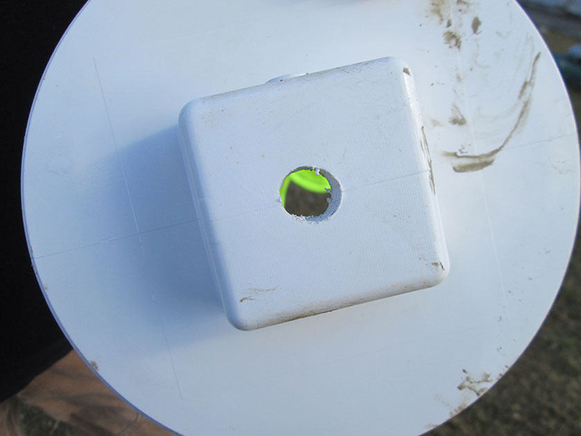
An orifice is a circular or rectangular opening of a prescribed shape and size that allows a controlled rate of release for outflow from an SMP when the orifice is submerged.
When Can Orifices Be Used?
An orifice is an outlet control that is typically applicable to bioinfiltration/bioretention basins, subsurface infiltration and detention SMPs, ponds and wet basins, and blue roofs. Depending on the site layout and stormwater conveyance design, they may be applicable to cisterns and media filters.
Orifices are suitable for SMPs of any size and can be used in conjunction with other outlet controls, such as weirs, to meet the Stormwater Regulations, if necessary.
Key Advantages of Orifices
- Are simple, passive structures that rely on gravity flow
- Can be variously sized to provide rate control for a wide variety of applications
- Multiple orifices may be located at the same or different elevations, if necessary, to meet performance requirements
- Allow for controlled drain down times
Key Limitations of Orifices
- May become clogged with sediment and debris, particularly traditional orifices with small diameters
- May be difficult to access for maintenance purposes when placed below grade
- Can concentrate flow and may cause erosive velocities
Key Design Considerations for Orifices
- Multiple orifices may be necessary to meet the Stormwater Regulations.
- Sizing is dependent upon release rate requirements, maximum ponding depth, and drain down time requirements.
- The orifice size that is needed to meet a certain release rate can be increased by reducing the head over the orifice, which can be achieved by enlarging the SMP’s footprint or adjusting overlying soil depths/cover for orifices below grade.
- Low flow devices can allow smaller release rates with larger orifices. The designer should explore all options before choosing a small orifice. The designer is referred to Section 4.12.9 for further information on low flow devices.
Figure 4.12‑1: Orifice with Typical Features
Orifice Design and Material Standards
- No underdrain orifice (i.e., that which is located at the capped end of an underdrain) may be smaller than 0.5 inches in diameter. No traditional orifice (i.e., that which is not part of an underdrain) may be smaller than one inch in diameter. (Download Underdrain Connection Standard Detail CAD File)
- Trash racks must be provided for all orifices draining surface basins.
- To prevent clogging, screening must be provided over any traditional orifice three inches in diameter or smaller. The dimensions of the openings within the screening must be half the diameter of the orifice. The screening should be separated from the orifice, not placed directly over the orifice. A minimum 12-inch sump must be provided beneath the invert of the orifice to prevent the collection of debris.
- For any traditional orifice three inches in diameter or smaller, an outlet structure box with one manhole access lid on each side of the weir wall is required for maintenance access. Adequate space to perform maintenance on the orifice must be provided on each side of the weir wall; it is recommended that at least four feet by three feet of space be provided on each side of the weir wall.
- Orifices must be designed and constructed of appropriate materials, taking flow velocities and exposure to the elements into consideration.
- Suitable access must be provided to inspect and maintain all orifices.
4.12.3 Weirs
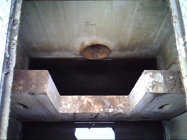
Weirs are engineered barriers/dams designed to control the release of stormwater from SMPs. Weirs can be located within surface SMPs or open channels or within outlet control structures. Typical weir shapes are rectangular, V-notch, and trapezoidal. Weir crests can be either sharp or broad.
Impermeable weirs controlling overland flow paths, such as swales, are typically called check dams. Impermeable check dams control upstream stormwater ponding depths and can be used to promote infiltration and/or sedimentation.
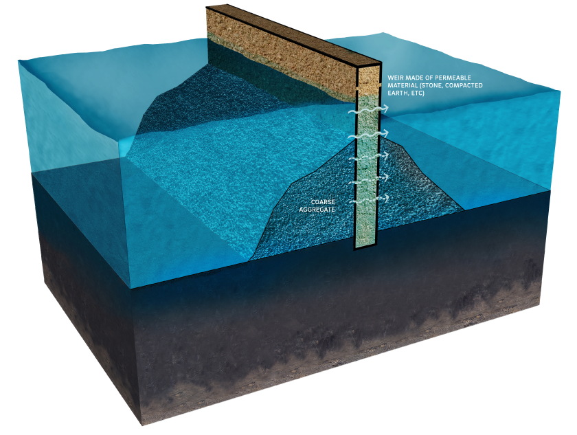
Permeable weirs promote sedimentation by slowing flow velocities as water ponds behind the weir. Under low flow conditions, water ponds behind the permeable weir and slowly seeps through the openings between the permeable weir materials. Under high flow conditions, water flows both over and through the weir. Permeable weirs also provide a means of spreading runoff as it is discharged, helping to decrease concentrated flow and reduce velocities as the water travels downstream. A common type of permeable weir is a stone check dam, which is typically located within overland flow paths, such as swales.
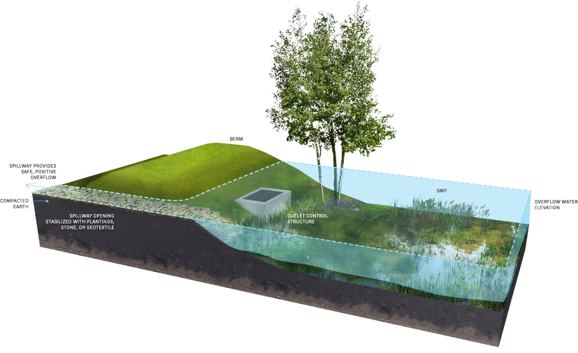
Spillways are weir outlet controls that are designed to provide safe, positive overflow from SMPs that store water on the surface, such as bioinfiltration/bioretention basins and ponds and wet basins. Spillways are typically trapezoidal, earthen, broad-crested weirs lined with riprap that allow for controlled flow of water over an SMP storage berm during extreme events.
When Can Weirs Be Used?
A weir is an outlet control that is typically applicable to bioinfiltration/bioretention basins, subsurface infiltration and detention SMPs, and ponds and wet basins. Depending on the site layout and stormwater conveyance design, they may be applicable to blue roofs, cisterns, and media filters.
Weirs are suitable for SMPs of any size and can be used in conjunction with other outlet controls, such as orifices, to meet the Stormwater Regulations, if necessary. Sizing of weirs is dependent upon release rate requirements, maximum ponding depth, and drain down time requirements.
Weirs can be used to do the following:
- Increase storage within surface depressions such as swales;
- Encourage ponding in areas where settling of solids and infiltration through vegetation and soil media can occur;
- Discharge overflow or bypass flow within an SMP to downstream conveyance systems; and/or
- Dissipate energy, reduce peak release rates, and control erosion.
A permeable weir is typically applicable to ponds and wet basins and swales. Depending on the site layout and stormwater conveyance design, permeable weirs may also be applicable to bioinfiltration/bioretention basins. On a variety of sites, they can act as a stone check dam, placed in a ditch or swale, and allow for water to flow through the weir, as opposed to an impermeable weir. Permeable weirs are most often used in large drainage areas within regional SMPs.
A spillway is typically applicable to bioinfiltration/bioretention basins and ponds and wet basins.
Figure 4.12‑2: Weir with Typical Features
Key Advantages of Weirs
- Are easily maintained
- May be surface-level structures that can usually be more easily accessed and maintained than closed systems
Key Limitations of Weirs
- Can concentrate flow and may cause erosive velocities
- Are not typically an effective technology for providing controlled discharge of stormwater
- May become clogged over time, if permeable, and, once clogged, would likely require full replacement
Key Design Considerations for Weirs
- Permeable weirs can include decorative stone caps.
- One stone size for a stone check dam is recommended for ease of construction. However, if two or more stone sizes are used, a larger stone should be placed on the outer layer and downstream side, since flows are concentrated at the exit channel of the weir. Several feet of smaller stone can then be placed on the upstream side. Smaller stone may also be more appropriate at the base of the dam for constructability purposes.
Figure 4.12‑3: Permeable Weir with Typical Features
Weir Design and Material Standards
- Design of weirs must consider structural stability during extreme conditions, including flow velocities and upstream hydrostatic pressure from ponded water. Structural supports must be designed by a structural engineer.
- Weirs must be designed and constructed with appropriate materials taking flow velocities and their exposure to the elements into consideration.
- Impermeable Weirs
- When placed within swales, check dams must be evenly spaced and no more than six to 12 inches high.
- Check dams that provide ponding in swales and are designed for infiltration must not be porous, as water should be ponded behind each check dam and forced to infiltrate.
- Permeable weirs must be avoided in areas that receive high sediment loads.
- Spillways
- A minimum of one foot of freeboard must be provided between the ponding elevation during the 100-year, 24-hour storm event, or, if the project is exempt from Flood Control, the ten-year, 24-hour storm, and the invert elevation of the emergency spillway.
- A minimum of one foot must be provided between the invert elevation of the emergency spillway and the top-of-berm elevation.
- All emergency spillways must be stabilized with stone, geotextile, or plant material that can withstand strong flows.
- Spillway flow must not be directed toward neighboring properties.
- Weir walls within outlet control structures must be poured monolithically.
Figure 4.12‑4: Spillway with Typical Features
4.12.4 Risers
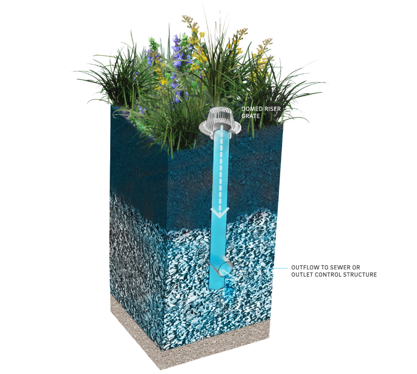
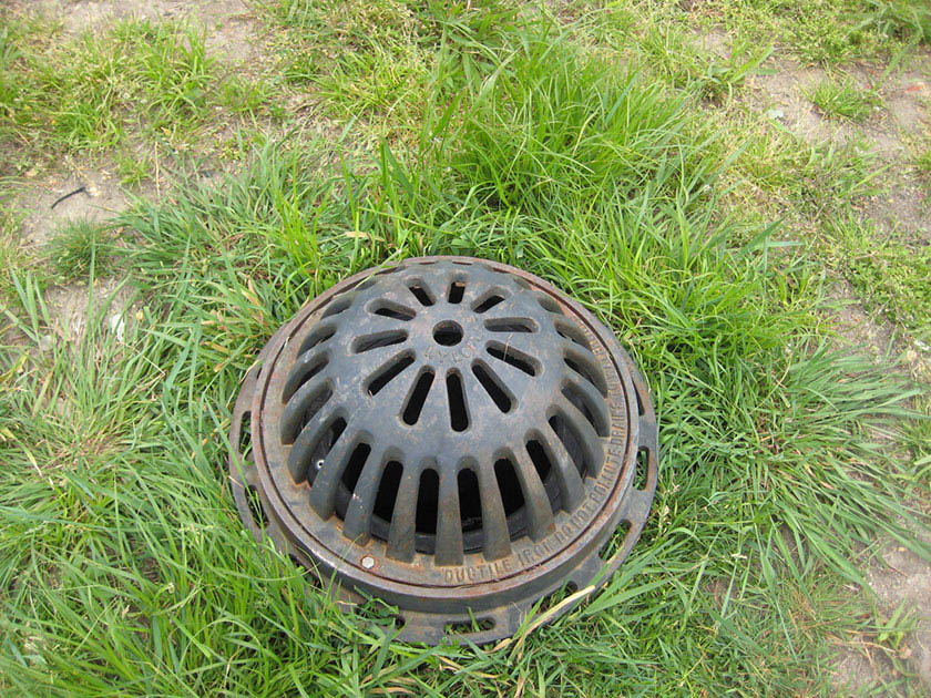
Risers are vertical structures with a grated top that can be designed to control the amount of water ponded within an SMP and to provide positive overflow. Riser pipes are vertical pipes topped with a dome-shaped grate. Riser boxes are modified concrete boxes (outlet control structures) outfitted with inlet grates. Orifices may also be placed on the upstream face and sides of a riser box to create a multi-stage riser.
When Can Risers Be Used?
A riser is an outlet control that is typically applicable to bioinfiltration/bioretention basins, and ponds and wet basins. Depending on the site layout and stormwater conveyance design, they may be applicable to blue roofs and green roofs. Risers can be used to control ponding depths and release water at a reduced rate. Risers can be used in conjunction with orifices, weirs, or underdrains, as necessary, to meet the Stormwater Regulations.
Key Advantages of Risers
- Provide flexible outlet controls, when multi-staged, to meet varying Stormwater Regulations simultaneously
Key Limitations of Risers
- Can be aesthetically displeasing
Key Design Considerations for Risers
- Concrete form liners and surrounding risers with vegetation can be used to improve aesthetics.
- Location of a riser is important to provide easy maintenance access, and risers should not be placed near inflow structures in order to avoid shortcutting of treatment.
Figure 4.12‑5: Riser Pipe with Typical Features
Riser Design and Material Standards
(Download Riser Outlet Control Structure Standard Detail CAD File)
- Riser design must balance providing positive overflow with allowing for adequate static storage. Overflow must be provided at the maximum Water Quality storm ponding depth for all SMPs and, for bioinfiltration/bioretention basins, at the minimum height to provide sufficient static storage of the Water Quality Volume (WQv).
- Riser pipes must be constructed of high-density polyethylene (HDPE) plastic, corrugated metal, concrete, or other weather resistant material.
- Riser boxes must be constructed of precast or cast-in-place concrete with reinforcing as warranted. All concrete must be Class C, conforming to the specifications of the City of Philadelphia Department of Streets, Standard Construction Items (1997).
- Trash racks or screens are required and must be constructed of durable, weather-resistant materials resistant to photo-degradation, weathering, oxidation, or other corrosive impacts.
4.12.5 Underdrains
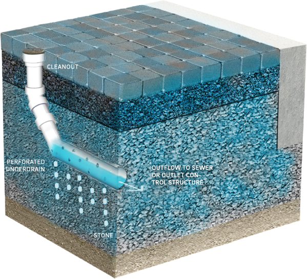
Underdrains are typically perforated pipes in stone layers or trenches that intercept, collect, and convey stormwater that has percolated through soil, a suitable aggregate, and/or geotextile, in order to drain the SMP after a storm event, allowing its storage volume to be available for subsequent storms. Underdrains can be connected to an outlet control structure that then controls the ponding elevation or release rate through weirs and/or orifices.
When Can Underdrains Be Used?
An underdrain is an outlet control that is typically applicable to bioinfiltration/bioretention basins. Depending on the site layout and stormwater conveyance design, they may be applicable to porous pavement, subsurface infiltration and detention SMPs, and media filters.
Underdrains can be used to collect runoff from media storage beds for non-infiltrating SMPs. Underdrains can be used when sub-soils are not appropriate for infiltration (e.g., karst geology, massive structure, known contaminants, etc.).
Capped underdrains are required for all bioinfiltration/bioretention SMPs. The designer is referred to Section 4.1 for design guidance on flow-regulating underdrains for bioinfiltration/bioretention SMPs.
Key Advantages of Underdrains
- Can collect stormwater over a large surface area
- Allow for vegetative and media filtration prior to release of stormwater into downstream conveyance systems
- Allow for vegetated or filtering practices to be placed in areas where infiltration is infeasible
Key Limitations of Underdrains
- May require maintenance, inspection, and replacement that can be difficult since the systems are typically buried underneath stone and, sometimes, soil
- Can experience inhibited performance due to root intrusion, if not properly controlled
Key Design Considerations for Underdrains
- To help prevent or minimize the potential for root intrusion, trees with aggressive root systems should be located away from underdrains.
Figure 4.12‑6: Underdrain with Typical Features
Underdrain Design and Material Standards
(Download Underdrain Connection Standard Detail CAD File)
(Download Underdrain Orifice Standard Detail CAD File)
- Capped underdrains are required for all bioinfiltration/bioretention SMPs. For bioinfiltration SMPs, the cap at the end located within the outlet control structure must be a solid cover to promote infiltration. For bioretention SMPs, the cap within the outlet control structure must be outfitted with an orifice, sized appropriately to meet all applicable release rate requirements.
- Underdrains must be designed to be level (i.e., with no slope).
- Underdrains must be made of continuously perforated HDPE plastic piping with a smooth interior and a minimum inner diameter of four inches. HDPE pipe must meet the specifications of AASHTO M252, Type S or AASHTO M294, Type S.
- Underdrains must be surrounded by a sand or stone layer to filter sediment and facilitate drainage.
- The minimum allowable thickness of a sand or stone filter layer is six inches both above and beneath the underdrain.
- To prevent clogging, underdrain pipes must be surrounded by geotextile fabric if a sand layer is used.
- Stone surrounding an underdrain must be uniformly graded, crushed, clean-washed stone. PWD defines “clean-washed” as having less than 0.5% wash loss, by mass, when tested per AASHTO T-11 wash loss test. AASHTO No. 3 and No. 57 stone can meet this specification.
- Sand, if used, must be AASHTO M-6 or ASTM C-33 sand and must have a grain size of 0.02 inches to 0.04 inches.
- Geotextile fabric must be placed between the stone layer and surrounding soil to prevent sediment contamination.
- Geotextile must consist of polypropylene fibers and meet the following specifications (AASHTO Class 1 or Class 2 geotextile is recommended):
- Grab Tensile Strength (ASTM-D4632): ≥ 120 lbs
- Mullen Burst Strength (ASTM-D3786): ≥ 225 psi
- Flow Rate (ASTM-D4491): ≥ 95 gal/min/ft2
- UV Resistance after 500 hrs (ASTM-D4355): ≥ 70%
- Heat-set or heat-calendared fabrics are not permitted.
- Cleanouts or maintenance access structures must be provided at the end of all underdrain pipes.
- Cleanouts must be provided for all 90-degree bends, located upstream of complicated bends, and evenly spaced during straight pipe runs.
- All intermediate cleanouts and domed riser pipe connections must be located upstream of the connected outlet control structure to allow for cleaning equipment to flush in the direction of the structure.
- An anti-seep collar must be installed around outlet pipes passing through embankments. Anti-seep collars must be constructed in accordance with the latest edition of the PA DEP Erosion and Sediment Pollution Control Program Manual.
- Cleanouts must be made of material with a smooth interior having a minimum inner diameter of four inches. The diameter of the cleanout must match the diameter of its connecting pipe up to eight inches. If the pipe is larger than eight inches in diameter, then the cleanout must be eight inches in diameter.
- The outlet pipe of an outlet control structure must have an invert at or below the invert of the underdrain. Setting the outlet pipe invert at a minimum of 7.5 inches below that of the underdrain is recommended.
4.12.6 Level Spreaders
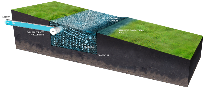
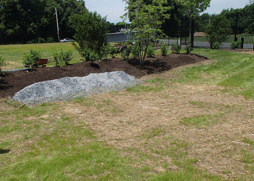
Level spreaders are outlet controls that are designed to uniformly distribute concentrated flow over a large area. Level spreaders help reduce concentrated flow, thereby reducing erosion and increasing the design life of many SMPs.
All level spreader designs follow the same principles:
- Concentrated flow enters the spreader at a single point such as a pipe, swale, or curb opening.
- The flow is slowed, and energy is dissipated.
- The flow is distributed throughout a long, linear, shallow trench or behind a low berm.
- Water then flows over the berm or edge of trench uniformly along the entire length.
There are many types of level spreaders that can be selected based on the peak rate of inflow, the duration of use, and the site conditions. Examples of level spreaders include subsurface discharge through level perforated pipes (bubble-up level spreader), concrete curbs, half-sections of pipe, troughs, and surface discharge to plunge pools.
When Can Level Spreaders Be Used?
A level spreader is an outlet control that is typically applicable to bioinfiltration/bioretention basins, ponds and wet basins, and subsurface infiltration and detention SMPs. Depending on the site layout and stormwater conveyance design, they may be applicable to media filters. They are suitable as outlet controls for pretreatment structures such as forebays and at locations where SMPs cannot discharge to the City sewer and/or must outfall to open spaces. Plunge pools can be used in combination with concrete curbing and/or trough level spreaders.
Key Advantages of Level Spreaders
- Reduce velocities, reducing the potential for erosive conditions
- Eliminate the need for larger outlets and/or conveyance systems in some instances
Key Limitations of Level Spreaders
- Not effective for providing rate control
- Have strong failure potential if soils are not protected from compaction and settlement; performance is strongly influenced by relatively small changes in elevation
- Require a relatively flat grade and downslope pervious areas onto which the spread flow can be discharged
- Can require 100 feet in downstream length in certain scenarios
- May be rendered ineffective by high sediment load deposition on the surface
Key Design Considerations for Level Spreaders
- The depths of trough or pipe level spreaders will depend on the flow. If sediment or debris accumulates in the trough or pipe, it can be easily removed.
- Concrete troughs are generally a more expensive level spreader alternative; however, they are easy to maintain and typically have a longer design life.
- Long-term maintenance and replacement costs can be decreased with proper installation.
Figure 4.12‑7: Level Spreader with Typical Features
Level Spreader Design and Material Standards
- The following level spreader lengths are required by cover condition:
- Dense grass ground cover: 13 linear feet for every one cubic feet per second (cfs) of flow during the ten-year, 24-hour storm event
- Forested areas with no ground cover: 100 linear feet for every one cfs of flow during the ten-year, 24-hour storm event
- Level spreaders must safely diffuse flows up to, and including, the 100-year, 24-hour storm event.
- It is critical that the edge over which flow is distributed is exactly level. If there are small variations in height on the downstream lip, small rivulets will form. Experience suggests that variations of more than 0.25 inches can cause water to re-concentrate and potentially cause erosion downstream of the level spreader. The site selected for the installation of a level spreader must be a level grade (a constant horizontal elevation, to within +/- four inches).
- The downslope side of the level spreader must be clear of debris. After construction, debris such as soil, wood, and other organic matter might accumulate immediately downstream of the level spreader. This effectively blocks water as it flows out of the level spreader, forcing it to re-concentrate.
- The downstream side of the level spreader must be fully stabilized before the level spreader is installed. If a level spreader is installed above a disturbed area without sufficient vegetative cover or other ground cover such as mulch or construction matting, erosion rills will quickly form. Even sheet flow can cause significant downstream erosion on disturbed areas. The first three feet downslope of a level spreader must be stabilized with soil/turf reinforcement matting and grass or other approved vegetation.
- Level spreaders cannot be constructed in newly deposited fill. Undisturbed earth is much more resistant to erosion than fill. Erosion is even likely to occur over a well-established young stand of grass planted on fill.
- For level spreaders that do not direct discharge to a receiving stream or sewer, the minimum distance between the level spreader and any downslope property boundary must be 15 feet. If this requirement cannot be met, a drainage easement may be required.
- For level spreaders that direct discharge to a receiving stream or sewer via overland flow, the maximum distance between the level spreader and any receiving stream or sewer must be 100 feet. Distances greater than 100 feet but less than 150 feet may be considered on a case-by-case basis for very mild slopes (less than or equal to 1%) and heavily vegetated (grassy) areas.
- The first ten feet downslope of the level spreader must not exceed a slope of 4%.
- Earthen berms must not be used as level spreaders due to the difficulty of grading a level edge within acceptable tolerances.
- Treated lumber must not be used as level spreaders due to issues with deformation and decomposition.
- Geotextile-covered berms must not be used as level spreaders.
- Concrete Curbs, Troughs, and Half-Pipes:
- Concrete curbs, troughs, and half-sections of pipe must be between four and 12 inches deep.
- Curbs and troughs must be constructed of Class C concrete or reinforced concrete, conforming to the specifications of the City of Philadelphia Department of Streets, Standard Construction Items (1997).
- Half-pipes must be either Class C concrete or reinforced concrete, conforming to the specifications of the City of Philadelphia Department of Streets, Standard Construction Items (1997) or HDPE plastic meeting the specifications of AASHTO M252, Type S or AASHTO M294, Type S.
- Subsurface Discharge Through Level Perforated Pipes (Bubble-Up Level Spreaders)
- Perforated pipes must be between four and 12 inches in diameter. HDPE pipe must meet AASHTO M252, Type S or AASHTO M294, Type S standards.
- The pipes must be enveloped in uniformly graded, crushed, clean-washed stone. PWD defines “clean-washed” as having less than 0.5% wash loss, by mass, when tested per AASHTO T-11 wash loss test. AASHTO No. 3 and No. 57 stone can meet this specification.
- Geotextile must be placed between the stone aggregate and soil.
- Geotextile must consist of polypropylene fibers and meet the following specifications (AASHTO Class 1 or Class 2 geotextile is recommended):
- Grab Tensile Strength (ASTM-D4632): ≥ 120 lbs
- Mullen Burst Strength (ASTM-D3786): ≥ 225 psi
- Flow Rate (ASTM-D4491): ≥ 95 gal/min/ft2
- UV Resistance after 500 hrs (ASTM-D4355): ≥ 70%
- Heat-set or heat-calendared fabrics are not permitted.
- Perforated pipes must include end treatments consisting of cleanouts, inlets, or manholes for maintenance purposes.
- Surface Discharge to Plunge Pools
- Underlying soils within plunge pools must remain undisturbed, uncompacted, and protected from heavy equipment to preserve infiltration capacities.
- Riprap stone sizing must be determined in accordance with the riprap apron design procedures in the latest edition of the PA DEP Erosion and Sediment Pollution Control Program Manual.
4.12.7 Impervious Liners
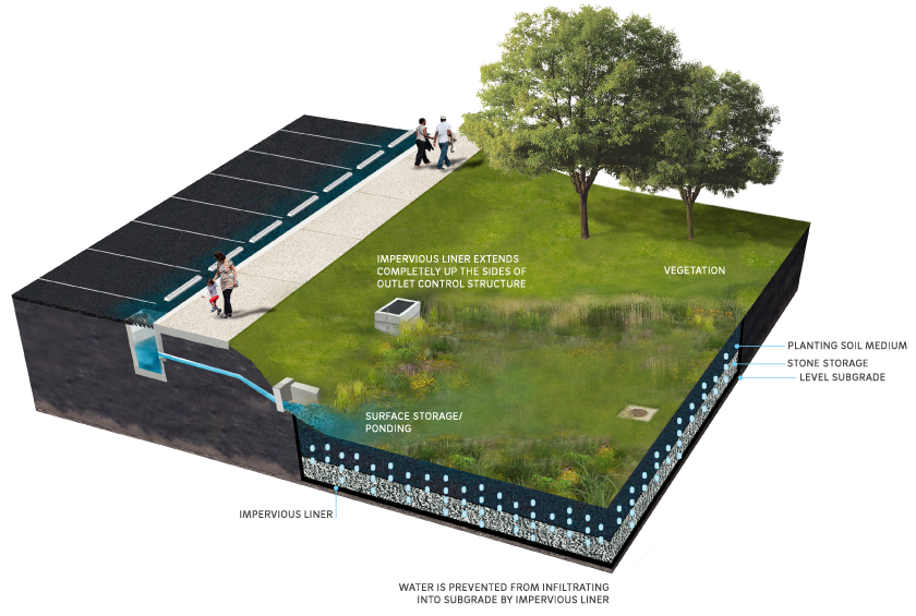
Impervious, or impermeable, liners prevent water from crossing a system boundary such as infiltrating through the subgrade beneath an SMP. Impervious liners include, but are not limited to, compacted till liners, clay liners, geomembrane liners, and concrete liners.

When Can Impervious Liners Be Used?
An impervious liner is an outlet control that is typically applicable to green roofs and blue roofs. Depending on the site layout and stormwater conveyance design, they may be applicable to bioretention basins, cisterns, ponds and wet basins, and subsurface detention SMPs. Impervious liners are only permitted in instances where placement is over in situ soils in which infiltration is restricted due to geotechnical concerns, such as over contaminated soils and brownfields, or adjacent to structures.
Key Advantages of Impervious Liners
- Prevent infiltration in areas of contamination or adjacent to subsurface structures in need of protection from potential flooding or seepage
Key Limitations of Impervious Liners
- Not readily visible for maintenance inspections
- Typically require significant excavation to repair
Key Design Considerations for Impervious Liners
- Impervious liners are not required for all non-infiltrating SMPs. For example, even if the infiltration potential of underlying soils is limited due to low infiltration rates, bioretention SMPs must be constructed without impervious liners.
- Clay liners should be of an appropriate design as specified by a geotechnical engineer.
Figure 4.12‑8: Impervious Liner with Typical Features
Impervious Liner Design and Material Standards
- Impervious liners are required, as appropriate, to prevent infiltration into areas of soil contamination.
- Impervious liners, if needed, must be installed to prevent infiltration SMPs from infiltrating stormwater within the zone of influence of any nearby sewers or sewer laterals. The zone of influence is defined by the area within a 1:1 (H:V) slope line from the outer edge of a sewer or sewer lateral.
- All impervious liners must exhibit a permeability less than or equal to 10-6 cm/sec.
- Impervious liners must be continuous and extend completely up the sides of any structures that are located within the lined basin footprint to the ground surface. If additional liner material must be added to extend up the structures, the additional liner sections must be joined to the rest of the liner with an impervious seam per the manufacturers’ recommendation.
- Compacted Till Liners:
- The minimum allowable compacted till liner thickness is 18 inches (after compaction).
- Soil must be compacted to 95% minimum dry density, modified proctor method (ASTM D-1557).
- Soil must be placed in six-inch lifts.
- Soils to be used must meet the gradation in Table 4.12‑3:
Table 4.12‑3: Compacted Till Liner Soil Gradation
| Sieve Size | Percent Passing |
|---|---|
| 6-inch | 100 |
| #4 | 70-100 |
| #200 | 20 |
- Clay Liners
- The minimum allowable clay liner thickness is 12 inches (after compaction).
- Clay liners must conform to the specifications outlined in Table 4.12‑4, per the Stormwater Management Manual for Western Washington (2012):
Table 4.12‑4: Clay Liner Specifications
| Property | Test Method | Unit | Specifications |
|---|---|---|---|
| Permeability | ASTM D-2434 | cm/sec | 1 x 10⁻⁶ max. |
| Plasticity Index of Clay | ASTM D-423 & D-424 | Percent | Not less than 15 |
| Liquid Limit of Clay | ASTM D-2216 | Percent | Not less than 30 |
| Clay Particles Passing | ASTM D-422 | Percent | Not less than 30 |
| Clay Compaction | ASTM D-2216 | Percent | 95% of Standard Proctor Density |
- Geomembrane Liners
- Geomembrane liner material must be smooth high-density polyethylene (HDPE) or linear low-density polyethylene (LLDPE) with a minimum thickness of 30 mil.
- Geomembrane liner material must be resistant to mildew, rot, ultraviolet radiation, insects, and rodents.
- Geotextile must be placed between the geomembrane liner and the stone storage layer, and it must meet, or exceed, the strength properties outlined in Table 4.12‑5, per Volume 3 Stormwater Flow Control & Water Quality Treatment Technical Requirements Manual 2009.
- A sand layer must be placed beneath the geomembrane liner to prevent puncture of the liner.
- Smooth HDPE and LLDPE geomembrane liners must conform to the physical requirements stipulated in the Geosynthetic Research Institute (GRI) GM13 and GM17 Standard Specifications for HDPE and LLDPE geomembranes, respectively.
- Boot collars must be included at any point where a pipe penetrates a geomembrane liner. This includes utility crossings, distribution pipes, and underdrain pipes.
Table 4.12‑5: Geotextile Strength Properties for Impervious Liner Protection
| Geotextile Property | Test Method | Geotextile Property Requirements* |
|---|---|---|
| Grab Tensile Strength, in machine and x-machine direction | ASTM D4632 | ≥ 250 lbs. |
| Grab Failure Strain, in machine and x-machine direction | ASTM D4632 | > 50% |
| Seam Breaking Strength (if seams are present) | ASTM D4632 and ASTM D4884 (adapted for grab test) | ≥ 220 lbs. |
| Puncture Resistance | ASTM D4833 | ≥ 125 lbs. |
| Tear Strength, in machine and x-machine direction | ASTM D4533 | ≥ 90 lbs. |
| Ultraviolet (UV) Radiation | ASTM D4355 | ≥ 50% strength stability retained, after 500 hrs. in weatherometer |
- Concrete Liners:
- Concrete must be minimum five inches thick, Class A or better, with ordinary surface finish.
- When underlying soil is clay or if it has an unconfined compressive strength of 0.25 tons per square foot or less, the concrete must have a minimum six-inch compacted aggregate base composed of coarse sand and river stone, crushed stone, or equivalent, with diameter of 0.75 inch to one inch.
- Anti-seep collars must be provided on all pipes entering or exiting the storage media of infiltrating SMPs where infiltration is not desired outside of the system (e.g. pipes that cross utilities and underdrain connections to the sewer-connected inlet). Where space allows, anti-seep collar should be placed offset from the SMP.
4.12.8 Micro Siphon Drain Belts
Micro siphon drain belts are drainage systems that use capillary pressure to wick water out of the soil or filter media and convey it through small siphon channels to collector drain pipes. They are typically flexible, extruded, PVC strips of variable widths with micro channels on one side. The belts can be installed at various depths within filter media or underlying soil, and their flexible shape can contour to the shape of the installed surface. Micro siphon drain belts may be used in combination with other techniques, such as layering of porous media to regulate outflow. They can also be connected to underdrains and used in conjunction with outlet control structures.
When Can Micro Siphon Drain Belts Be Used?
Depending on the site layout and stormwater conveyance design, micro siphon drain belts may be applicable to bioretention basins, subsurface detention SMPs, ponds and wet basins, green roofs, and media filters. Micro siphon drain belts can be used in conjunction with underdrains and impervious liners when infiltration is not feasible. For example, they can be used to collect and convey drainage from a large area to a central underdrain. They can also be used for applications in which water must be drawn away from foundations, retaining walls, or other boundaries.
Key Advantages of Micro Siphon Drain Belts
- Can meet very low release rate requirements
- Can collect stormwater over a large surface area
- Allow for vegetative and media filtration prior to the release of stormwater back into downstream conveyance systems
- Resist clogging, as the capillary action that pulls water into the micro channels does not transport solids
- Constructed of material that is both flexible and durable, making the belts easy to install and resistant to compression or other degradation over time
Key Limitations of Micro Siphon Drain Belts
- Have limited system depth due to maximum allowable head
- Do not allow for inspection of system without excavation
Key Design Considerations for Micro Siphon Drain Belts
- Installation with the micro channels facing downward limits clogging of the micro channels, as gravity allows particulates to fall out when water is pulled into the micro siphon channels.
- To help prevent or minimize the potential for clogging by root intrusion, locate trees and plants with aggressive root systems away from micro siphon drain belts.
Micro Siphon Drain Belt Design and Material Standards
- Micro siphon drain belts must connect to a downslope underdrain or collector pipe. The elevation of the belt in the immediate vicinity of the downslope connection must be at least four inches above the top of the underdrain or collector pipe.
- The end of the micro siphon drain belt that is not connected to the collector pipe must be sealed to prevent the intrusion of solids or other clogging materials. The sealant must be suitable for use in submerged environments.
- A minimum belt slope of 1% is required to ensure drainage, but a belt slope of 3% to 5% is recommended to maintain laminar flow within the micro channels.
- Micro siphon drain belts must be installed in a layer of sand. Sand used must be ASTM C-33 aggregate concrete sand with grain size between 0.02 inches and 0.08 inches.
- Manufacturer’s recommendations must be followed to determine the number, size, and specific configuration of belts required to provide adequate flow capacity for specific applications.
- Micro siphon drain belts must be spaced around the underdrain or collector drain pipe at a maximum of alternating five-foot centers.
4.12.9 Low Flow Devices
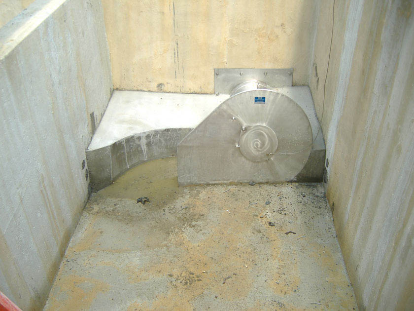
Low flow devices are prefabricated or proprietary systems that regulate the discharge flow rate from SMPs. Types of low flow devices include, but are not limited to, floating or constant-head orifices and vortex outlet control devices. Floating or constant-head orifices regulate low flow discharges through the use of a floating intake structure. Vortex outlet control devices use induced helical flow to restrict flow rates.
Low flow devices are evaluated on a project-specific basis since site conditions, such as sediment loading and/or drainage area size, can impact a product’s ability to meet Stormwater Regulations. PWD has developed a list, accessible on the PWD Stormwater Plan Review website, of low flow devices that may be used to comply with the Stormwater Regulations.
When Can Low Flow Devices Be Used?
A low flow device is an outlet control that is typically applicable to subsurface detention SMPs. Depending on the site layout and stormwater conveyance design, low flow devices may be applicable to bioretention basins, cisterns, ponds and wet basins, green roofs, blue roofs, and media filters. A low flow device can be used to assist with meeting small release rate requirements, particularly for small drainage areas and sites with challenging design constraints for which the implementation of traditional slow release outlet devices, such as orifices, does not allow for compliance.
Key Advantages of Low Flow Devices
- Allow SMPs with footprint constraints to meet maximum release rate requirements
- Allow smaller release rates with larger orifice diameters than traditional orifice outlet controls, alleviating clogging and other operational concerns
- Accompanied by manufacturer’s readily available product specifications, design guidance, installation considerations, and expected performance
Key Limitations of Low Flow Devices
- More difficult to customize to the particular requirements of individual sites because they are pre-engineered devices
- May require more intensive inspection and maintenance than more traditional, passive outlet controls
Key Design Considerations for Low Flow Devices
- Design specifications and vendor information should be carefully reviewed to assess likely performance, maintenance, and longevity.
- Products used within ultra-urban settings that have demonstrated a strong track record of performance should be prioritized for design.
- The effective head on the orifice, release rate requirements, and its opening size should all be evaluated to determine an appropriate product based on manufacturer-provided performance curves.
Low Flow Device Design and Material Standards
- The following information must be submitted for each proposed low flow device as part of the applicant’s Post‑Construction Stormwater Management Plan (PCSMP) Review Phase Submission Package. Preliminary consultations with PWD prior to submission are encouraged.
- Performance/discharge curves;
- Third-party certifications;
- Hydrologic and hydraulic model files, if applicable;
- Product specifications;
- Manufacturer’s guidelines for installation;
- Construction sequence; and
- Maintenance requirements, including product life and replacement schedule, if applicable
- Appropriate design measures must be taken to prevent clogging for all orifices.
- Suitable access must be provided to inspect and maintain all orifices.
