-
4.0 Introduction
Chapter 4, Stormwater Management Practice Guidance, provides detailed guidance to the designer regarding stormwater management practices (SMPs) as well as pretreatment, inlet and outlet control systems, and landscaping that support SMP functions.
4.0.1 How to use this chapter
Before using this chapter, the designer should first review the Philadelphia Water Department (PWD) Stormwater Regulations (Stormwater Regulations) outlined in Chapter 1 to assess what level of stormwater management a project will need to achieve compliance. It is also important for the designer to have made a preliminary determination of an appropriate Review Path for their project, which is covered in Chapter 2. Chapter 4 is only applicable for projects that fall under the Development Compliance Review Path (Section 2.2.1) and Stormwater Retrofit Review Path (Section 2.2.4).
For a project meeting Stormwater Regulations, the designer should have arrived at Chapter 4 after confirming, through a review of Chapter 3, that the project cannot show compliance with the Stormwater Regulations solely through use of non-structural design strategies (Section 3.1.4) and disconnected impervious cover (DIC; Section 3.1.5) and that SMPs are required. Before designing SMPs using the detailed guidance in Chapter 4, the designer should follow the SMP selection, layout, and design guidance in Section 3.2 and review the requirements for infiltration testing and soil assessment for SMP design in Section 3.3. The designer is also referred to Section 3.4 for detailed guidance on how to show compliance with the Stormwater Regulations or applicable design criteria, and to Section 3.5 for examples of stormwater management strategies that include SMPs. After the designer has selected the type(s) of SMP(s) needed on the project site, the designer can then refer to individual sections within Chapter 4 as needed to develop detailed designs of SMP(s) that comply with PWD requirements and standards.
4.0.2 Chapter organization
The SMPs in this chapter are presented in order of PWD preference according to the SMP Hierarchy (Section 3.2.2). Several SMPs in this chapter are on PWD’s list of acceptable non-infiltrating pollutant-reducing practices (Section 3.1.7).
This chapter consists of guidance and requirements for the following SMPs:
- Section 4.1 – Bioinfiltration/Bioretention
- Section 4.2 – Porous Surfaces
- Section 4.3 – Green Roofs
- Section 4.4 – Subsurface Infiltration
- Section 4.5 – Cisterns
- Section 4.6 – Blue Roofs
- Section 4.7 – Ponds and Wet Basins
- Section 4.8 – Subsurface Detention
- Section 4.9 – Media Filters
- Section 4.14 – Blue-Green Roofs
- Section 4.15 – Drainage Wells
Additionally, this chapter contains guidance and requirements for the following types of systems that support SMP function:
- Section 4.10 – Pretreatment
- Section 4.11 – Inlet Controls
- Section 4.12 – Outlet Controls
- Section 4.13 – Landscaping
Each SMP section in this chapter is organized into subsections that contain the following information:
- Introduction – Introduces the SMP; gives examples of when the SMP can be used; and describes key advantages, limitations, and design considerations.
- Components – Describes the typical SMP pretreatment, inlet control, storage area, outlet control, and inspection and maintenance access components, as applicable.
- Design standards – Lists all SMP design requirements, denoted by easy-to-reference numerals.
- Material standards – List all SMP material specifications and requirements, denoted by easy-to-reference numerals.
- Construction guidance – Provides guidance related to SMP construction.
- Maintenance guidance – Provides guidance on SMP maintenance activities and frequencies, including a recommended SMP maintenance schedule.
4.0.3 Design innovation
SMPs contained in this chapter are by no means exclusive. PWD encourages the development of innovative practices that meet the intent of the Stormwater Regulations. PWD recognizes that new stormwater management systems and products are being developed continuously and is in support of innovative approaches to management. The designer is encouraged to request a pre-application meeting with PWD Stormwater Plan Review early in the approval process to discuss PWD’s standard SMP design requirements or if the designer wishes to use new or non-standardized technologies to meet the Stormwater Regulations.
-
4.1 Bioinfiltration/Bioretention
Download summaries of this SMP and its maintenance guidance, with quick reference information for clients and developers:
- Bioinfiltration/Bioretention SMP One‑Sheet
- Bioinfiltration/Bioretention Maintenance Guidance One‑Sheet
4.1.1 Bioinfiltration/bioretention introduction
Bioinfiltration and bioretention stormwater management practices (SMPs), often referred to as rain gardens, are vegetated depressions or basins that use surface storage, vegetation, planting soil, outlet controls, and other components to treat, detain, and retain stormwater runoff. Bioinfiltration and bioretention SMPs represent the highest level of preference in the Philadelphia Water Department’s (PWD’s) SMP Hierarchy by providing high-performance and cost-effective stormwater management, green space, and triple bottom line benefits. Both types of SMPs reduce stormwater volume and pollution by filtering runoff through a vegetated soil medium that promotes evapotranspiration. Bioinfiltration SMPs remove stormwater via infiltration into the surrounding soils while bioretention SMPs attenuate runoff with flow-regulating underdrains.
Bioinfiltration/bioretention SMPs can be found in a variety of configurations, from relatively large and open vegetated basins to small-scale SMPs contained within flow-through planter boxes. These SMPs can be combined with other SMPs in series to meet the PWD Stormwater Regulations (Stormwater Regulations). The designer is referred to Section 3.2.3 for information on using SMPs in series.
Because bioinfiltration and bioretention SMPs are ranked highest in the SMP Hierarchy (Section 3.2.2), special design guidance is provided in this section to promote their use. This design guidance provides flexibility for designers to either dynamically model bioinfiltration or to follow a prescribed design based on the drainage area without performing infiltration testing. The dynamic routing allows designers to account for the volume of water infiltrated into the ground in real time, which allows the bioinfiltration SMP to have less storage and be shallower. The prescribed design makes use of the minimum requirements set forth in the Standard Detail (Figure 4.1‑4) and the Bioinfiltration/bioretention basin sizing table (Table 4.1‑4), ensuring that bioinfiltration/bioretention SMPs can be fully designed and approved for Water Quality compliance without knowledge of infiltration feasibility. Therefore, postponement of infiltration testing until construction of the evelopment project is permitted; the results of the infiltration testing will dictate whether an underdrain cap should be equipped with an orifice. Additionally, development projects incorporating only disconnected impervious cover and bioinfiltration/bioretention SMPs may be eligible for a Surface Green Review. The designer is referred to Section 2.4 for details on the Expedited Post‑Construction Stormwater Management Plan (PCSMP) Review submission process.
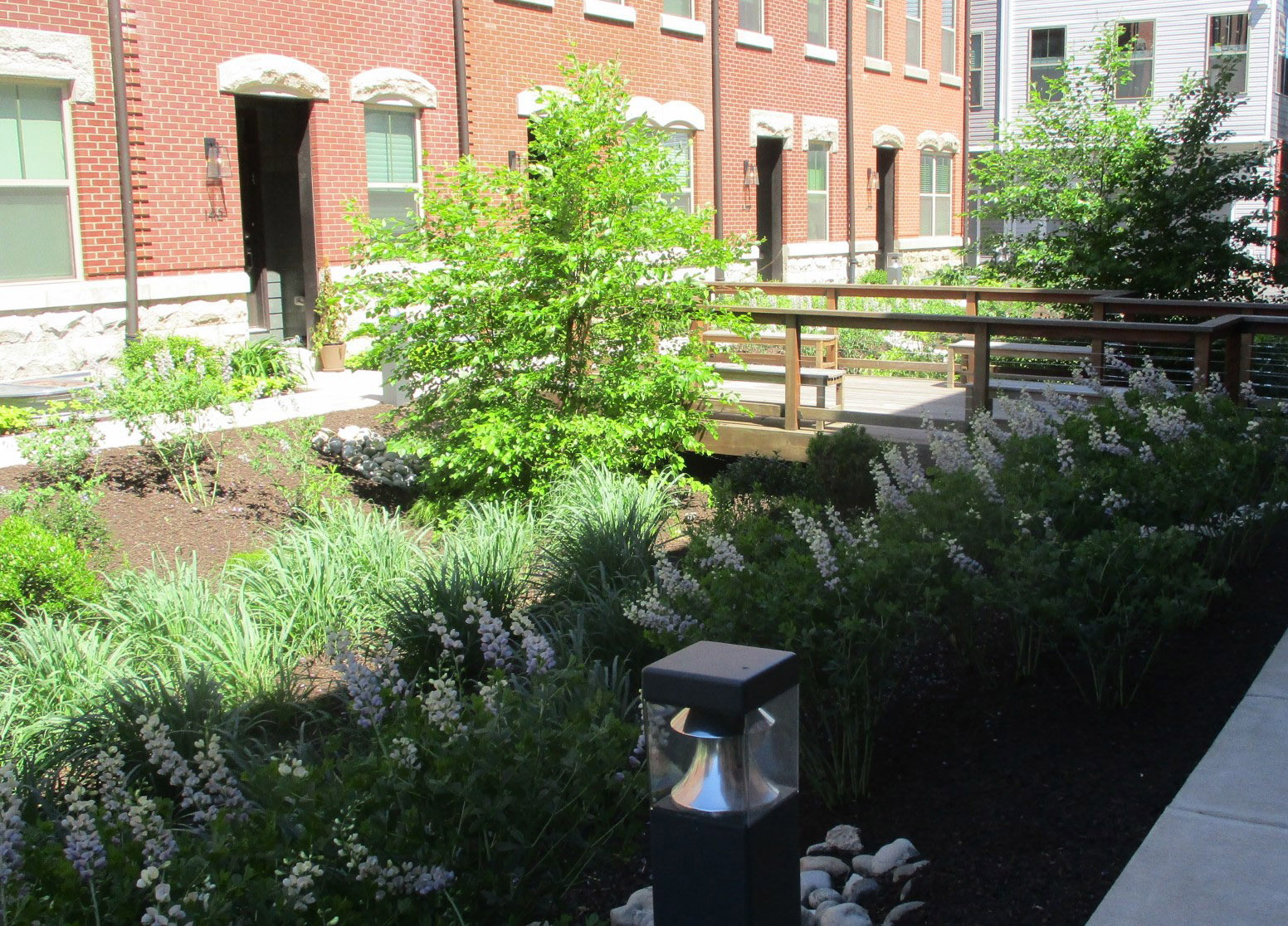
An example of a typical bioretention basin in Philadelphia When can bioinfiltration/bioretention be used?
Bioinfiltration SMPs must have underlying soils that, when tested pursuant to the infiltration testing procedure described in Section 3.3, are determined to be infiltration-feasible. Where infiltration is not feasible, bioretention SMPs can be used by converting capped underdrains to flow-regulating underdrains to comply with the Water Quality requirement. The designer is referred to Section 3.3 for guidance on infiltration testing.
Bioinfiltration/bioretention SMPs can be used to manage stormwater on small and large sites. For example, bioinfiltration/bioretention may be integrated into smaller sites using flow-through planter boxes or integrated into larger sites by using multiple bioinfiltration/bioretention basins throughout the project area.
Bioinfiltration/bioretention SMPs are also suitable for many types and sizes of development, from multi-family residential to high-density commercial projects, and are viewed as an integral part of a development’s landscape design during site layout, doubling as both a landscape amenity and stormwater management feature.
At commercial, industrial, and institutional sites, areas for stormwater management and green space are often limited. At these sites, bioinfiltration/bioretention SMPs serve multiple purposes of stormwater management and landscaping by managing runoff from impervious site areas such as parking lots, sidewalks, and rooftops. Bioinfiltration SMPs can also be dynamically sized to save space or reduce the depth of the SMP.
A parking lot is an ideal location for bioinfiltration/bioretention SMPs. These SMPs can be incorporated as an island, median, or along the perimeter of the parking area. Bioinfiltration/bioretention SMPs can enhance the aesthetics of a parking lot while managing stormwater from the site.
Key advantages of bioinfiltration/bioretention
- Flexible layout and easy to incorporate in landscaped areas
- Very effective at removing pollutants and reducing runoff volumes
- Generally, one of the more cost-effective stormwater management options
- Relatively low maintenance activities costs
- Can contribute to better air quality and help reduce urban heat island impacts
- Can improve property values and site aesthetics through attractive landscaping
- Can provide educational benefits, especially when used at public and/or highly visible sites such as schools, recreation centers, libraries, etc.
- Eligible for inclusion in an Expedited PCSMP Review project
- Above benefits may be maximized with the inclusion of trees
- Bioinfiltration SMPs are eligible for dynamic sizing
Key limitations of bioinfiltration/bioretention
- May need to be combined with other SMPs to meet the Flood Control requirement
- May have limited opportunities for implementation based on the amount of open space available at the site
Key design considerations for bioinfiltration/bioretention
- Bioinfiltration/bioretention SMPs should be considered as an alternative before designing subsurface infiltration and detention SMPs. Bioinfiltration/bioretention SMPs are preferred for several reasons, including installation and maintenance cost, ease of maintenance, habitat creation, nutrient cycling, and aesthetics.
- Bioinfiltration SMPs can be dynamically designed, which may save space or reduce the depth of the SMP. These SMPs must statically store one inch of runoff and be shown, via dynamic routing, to manage 1.5 inches of runoff throughout the design storm, without overflow.
- The pretreatment approach should be matched to site characteristics. Bioinfiltration/bioretention SMPs rely on flow through soil media to provide Water Quality treatment. Media layers can become clogged, particularly when runoff has high quantities of sediment. To avoid this, SMPs managing runoff from surfaces that generate high sediment loads should have adequate pretreatment to remove dirt and grit before they reach the bioinfiltration/bioretention SMP.
- The SMPs should be viewed as landscape features. Viewing bioinfiltration/bioretention SMPs as an integral part of a site’s landscape design can help identify key implementation locations. Bioinfiltration/bioretention SMPs can double as landscape features on many sites, providing landscape amenities and stormwater management in the same location.
- Non-basin designs can be used for small spaces. Integrating bioinfiltration/bioretention into flow-through planter boxes or tree pits can be an effective way of incorporating bioinfiltration/bioretention functions into spatially constrained sites.
- Safety issues relating to ponding depth should be carefully considered, particularly for sites where small children will be proximate to the installation.
- Balancing cut and fill can reduce costs. A berm placed on the downslope side of a mild slope can help retain stormwater and increase capacity without additional excavation.
- For constrained sites, using additional subsurface stone to meet storage volume needs should be considered. Bioinfiltration SMPs can also be dynamically designed to save space.
- Areas of soil contamination should be avoided; however, in some cases, an impervious liner may be appropriate for separating bioinfiltration/bioretention SMPs from these underlying conditions.
- Whenever possible, the designer should preserve existing trees and develop tree protection plans. A plan should be developed for the removal of invasive species both in and around the project area.
- A diverse planting palette should be used. A diverse community of native plants is recommended to minimize susceptibility to insect and disease infestation and reduce long-term maintenance requirements. A mixture of herbaceous plants, grasses, shrubs, and trees is generally recommended to create a microclimate that can ameliorate urban stresses, discourage weed growth, and reduce maintenance needs.
- Smart plant selection for the site should be a focus. It is critical that plant materials are appropriate for soil, hydrologic, light, and other site conditions. The designer is referred to the list of native and recommended non-invasive species in Appendix I. Ponding depth, drainage time, sunlight, salt tolerance, and other conditions should be taken into consideration when selecting plants. Turf grass is generally not recommended but may be acceptable provided the designer can demonstrate that it meets all applicable requirements. The designer is referred to Section 4.13, Landscaping, for additional guidance.
- The designer should choose low maintenance plants that minimize the need for mowing, pruning, and irrigation.
- The characteristics of the soil for the bioinfiltration/bioretention SMP are perhaps as important as the facility location, size, and treatment volume. The soil must be permeable enough to allow runoff to filter through the media, while having characteristics suitable to promote and sustain a robust vegetative cover crop. In addition, much of the nutrient pollutant uptake (nitrogen and phosphorus) is accomplished through adsorption and microbial activity within the soil profile. Therefore, the soils must balance soil chemistry and physical properties to support biotic communities above and below ground.
- Flow-through planter box planting requires that plants be supplied with nutrients that they would otherwise receive from being part of an ecosystem. Since they are cut off from these processes, they must be cared for accordingly.
- Generally, six‑inch to twelve‑inch centers with triangular spacings for plugs are recommended.
- Mulch for a bioinfiltration/bioretention SMP should have a minimum depth of two inches.
- For any bioinfiltration/bioretention SMP that discharges onto an adjacent property, a drainage easement may be required and is recommended.
4.1.2 Bioinfiltration/bioretention components
Figure 4.1‑1: Bioinfiltration/bioretention basin with typical features
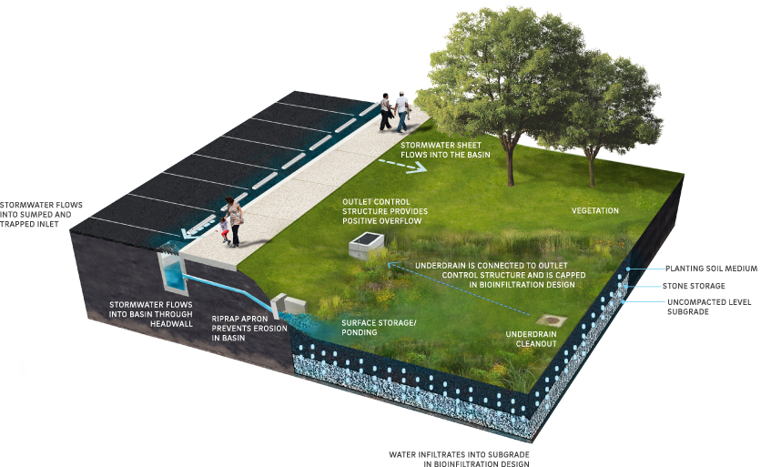
Pretreatment component
Pretreatment systems capture trash, sediment, and/or other pollutants from stormwater runoff before delivery to the storage or infiltration area. Pretreatment needs will vary significantly depending on the contributing drainage area composition and use. Pretreatment can include structures such as sumped and trapped inlets, sediment/grit chambers or separators, media filters, inlet inserts, or other appropriate prefabricated or proprietary designs to remove sediment, floatables, and/or hydrocarbons from stormwater runoff prior to being conveyed to a bioinfiltration/bioretention SMP. While inlet hoods are preferred, permanent filter bags may be accepted for Stormwater Retrofit projects where existing inlets do not have hoods and inlet reconstruction is not feasible. In addition to sumped and trapped inlets, permanent filter bag inserts are required for sites that generate pollutants such as loading docks, material storage facilities, junk yards, and waste collection and disposal sites. Permanent filter bags will require frequent cleanings.
Pretreatment can also consist of filter strips, forebays, and swales. The designer is referred to Section 4.10, Pretreatment, for more information.
Inlet control component
Inlet control systems convey and control the flow of stormwater from the contributing catchment area to a bioinfiltration/bioretention SMP. Inlet control needs will vary depending on the design of stormwater conveyance systems and the site layout. The designer is referred to Section 3.4.2 for guidance on stormwater conveyance system design.
Inlet controls may include flow splitters, curbless design/curb openings, energy dissipaters, and inlets. The designer is referred to Section 4.11, Inlet Controls, for more information.
Storage area component
Storage areas within bioinfiltration/bioretention SMPs temporarily hold stormwater runoff until it can either infiltrate into native soils, evaporate, be used by plants through transpiration, or be released downstream at a controlled rate, depending on the SMP design. Bioinfiltration/bioretention SMPs can include both surface and subsurface storage areas.
Surface storage is typically provided by excavating an area to create a depression. Surface storage for bioinfiltration/bioretention SMPs can also be created using curbing or concrete structures such as flow-through planter boxes. It provides temporary storage of stormwater runoff before infiltration, evaporation, and uptake can occur within the bioinfiltration/bioretention SMP. Ponding time provides Water Quality benefits by allowing larger debris and sediment to settle out of the water. Maximum surface ponding depth requirements are provided in order to reduce hydraulic loading on underlying soils, ensure adequate drain down time, and prevent standing water.
Figure 4.1‑2: Flow-through planter box with typical features
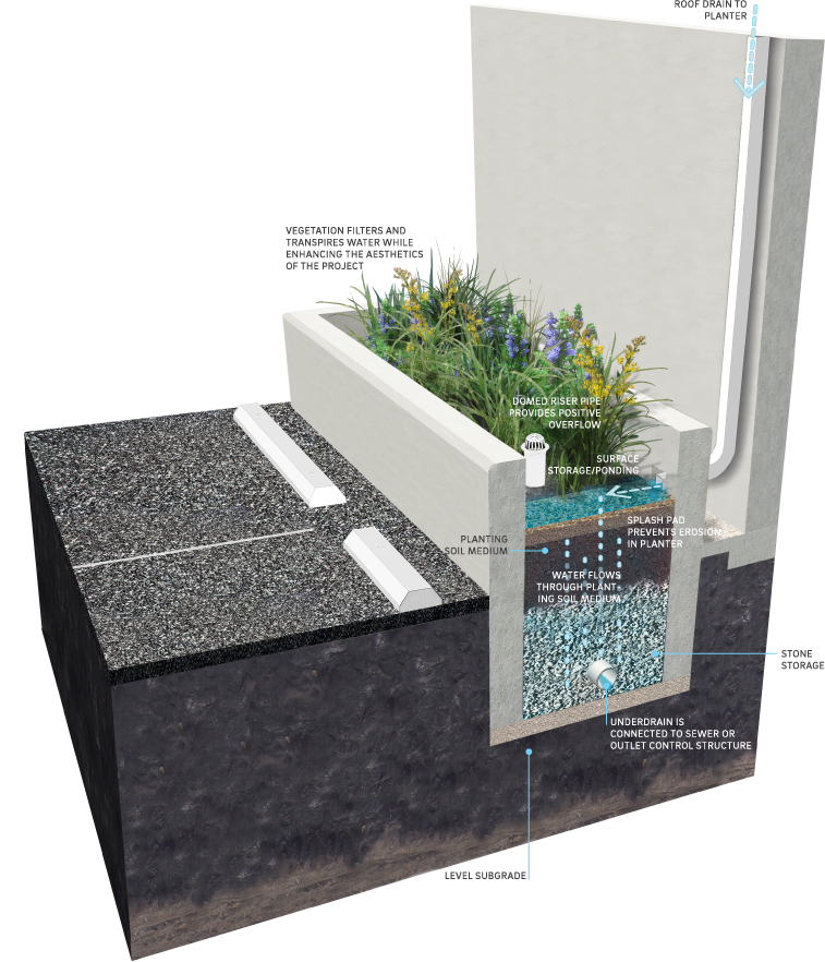
Beneath surface storage areas, prepared planting soil medium provides subsurface storage capacity. This storage capacity is a function of the soil depth, surface area, and void space. The planting soil medium serves as the primary Water Quality treatment mechanism of a bioinfiltration/bioretention SMP, filtering runoff before it reaches the native soil (for bioinfiltration SMPs) or before it reaches the downstream discharge point (for bioretention SMPs).
The characteristics of the soil for the bioinfiltration/bioretention SMP are perhaps as important as the facility location, size, and treatment volume. The soil must be permeable enough to allow runoff to filter through the media, while having characteristics suitable to promote and sustain a robust vegetative cover crop. In addition, much of the nutrient pollutant uptake (nitrogen and phosphorus) is accomplished through adsorption and microbial activity within the soil profile. Therefore, the soils must balance soil chemistry and physical properties to support biotic communities above and below ground.
Many bioinfiltration/bioretention SMPs include an additional subsurface storage component, typically constructed of a stone-filled, level-bottomed bed or trench. The void spaces between the stones store stormwater until it can infiltrate into the surrounding soils or be released downstream.
A mulch or organic layer, atop the planting soil medium, provides a medium for biological growth, decomposition of organic material, and adsorption of pollutants such as heavy metals. The mulch layer can also absorb some water during storms and help the planting soil retain water for plant growth during dry periods.
Vegetation component
Plant material in a bioinfiltration/bioretention SMP removes nutrients and stormwater pollutants through vegetative uptake and microbial community support, removes water through evapotranspiration, creates pathways for infiltration (in bioinfiltration SMPs) through root development and plant growth, improves aesthetics, provides habitat, and helps to stabilize soil.
The proper selection and installation of plant materials is critical to a successful bioinfiltration/bioretention SMP. There are essentially six zones within a bioinfiltration/bioretention SMP (Figure 4.1‑3). The lowest elevation supports plant species adapted to standing and fluctuating water levels. The middle elevation supports a slightly drier group of plants, but still tolerates fluctuating water levels. The outer edge is the highest elevation and generally supports plants adapted to drier conditions. However, plants in all zones should be drought tolerant.
Figure 4.1‑3: Hydrologic zones of a bioinfiltration/bioretention basin
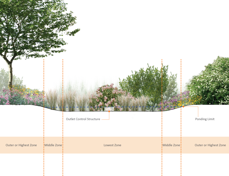
The lowest zone (hydrologic zones 2–4) contains plant species adapted to standing and fluctuating water levels and frequent inundation. Frequently used native plants include the following species. The designer is referred to Table I‑1 in Appendix I for a complete listing.
Table 4.1‑1: Frequently used native plants for hydrologic zones 2–4
Frequently used native plants for hydrologic zones 2–4 asters (Aster spp.) winterberry (Ilex verticillata) goldenrods (Solidago spp.) arrowwood (Viburnum dentatum) bergamot (Monarda fistulosa) sweet pepperbush (Clethra alnifolia) blue-flag iris (Iris versicolor) bayberry (Myrica pensylvanica) sedges (Carex spp.) buttonbush (Cephalanthus occidentalis) ironweed (Vernonia noveboracensis) swamp azalea (Rhododendron viscosum) blue vervain (Verbena hastata) elderberry (Sambucus canadensis) joe-pye weed (Eupatorium spp.) red maple (Acer rubrum) swamp milkweed (Asclepias incarnata) river birch (Betula nigra) switchgrass (Panicum virgatum) sweetgum (Liquidambar styraciflua) shrub dogwoods (Cornus spp.) northern white cedar (Juniperus virginiana) The middle zone (hydrologic zones 4–5) is slightly drier than the lowest zone, but plants should still tolerate fluctuating water levels. Frequently used native plants include the following species. The designer is referred to Table I‑1 in Appendix I for a complete listing.
Table 4.1‑2: Frequently used native plants for hydrologic zones 4–5
Frequently used native plants for hydrologic zones 4–5 black snakeroot (Cimicifuga racemosa) spicebush (Lindera benzoin) switchgrass (Panicum virgatum) hackberry (Celtis occidentalis) spotted joe-pye weed (Eupatorium maculatum) willow oak (Quercus phellos) cutleaf coneflower (Rudabeckia lacinata) winterberry (Ilex verticillata) frosted hawthorn (Crataegus pruinosa) slippery elm (Ulmus rubra) marginal wood fern (Dryopteris marginalis) viburnums (Viburnum spp.) ironwood (Carpinus caroliniana) witch-hazel (Hamamelis virginiana) serviceberry (Amelanchier canadensis) steeplebush (Spiraea tomentosa) obedient plant (Physostegia virginiana) blueberry (Vaccinium spp.) The outer zone (hydrologic zones 5–6) generally supports plants adapted to drier conditions. Frequently used native plants include the following species. The designer is referred to Table I‑1 in Appendix I for a complete listing.
Table 4.1‑3: Frequently used native plants for hydrologic zones 5–6
Frequently used native plants for hydrologic zones 5–6 basswood (Tilia americana) sweet-fern (Comptonia peregrina) white oak (Quercus alba) eastern red cedar (Juniperus virginiana) scarlet oak (Quercus coccinea) smooth serviceberry (Amelanchier laevis) black oak (Quercus velutina) American holly (Ilex opaca) american beech (Fagus grandifolia) sassafras (Sassafras albidum) black chokeberry (Aronia melanocarpa) white pine (Pinus strobus) Outlet control component
Outlet controls within a bioinfiltration/bioretention SMP can provide a range of functions, including the following:
- Controlling how much water is stored for infiltration (for bioinfiltration SMPs);
- Meeting drain down time requirements;
- Controlling the rate of discharge from the SMP and limiting water surface elevations during various storm events; and
- Bypassing of flows from large storm events.
Outlet controls may include orifices, weirs, risers, or underdrains. The designer is referred to Section 4.12, Outlet Controls, for more information.
Inspection and maintenance access component
Safe and easy inspection and maintenance access to all major components within a bioinfiltration/bioretention SMP is critical to ensuring long-term performance. Cleanouts provide a means to maintain any installed underdrains. Mildly sloping, stabilized, and graded areas also provide access to surface storage areas for heavy equipment, which may be needed for sediment removal.
4.1.3 Bioinfiltration/bioretention design standards
The designer is encouraged to design bioinfiltration/bioretention SMPs meeting the minimum requirements set forth in the Bioinfiltration/bioretention basin Standard Detail (Figure 4.1‑4) in conjunction with the Bioinfiltration/bioretention basin sizing table (Table 4.1‑4). Basins sized as such provide Water Quality compliance in all sewersheds and regardless of infiltration feasibility, with only minor modification necessary to the capped underdrain during construction. As a result, bioinfiltration/bioretention SMPs can be designed without knowledge of infiltration feasibility.
If infiltration is deemed feasible, the designer may elect to dynamically design the bioinfiltration SMP. The dynamically designed SMP must still meet all applicable requirements, but it may be designed to statically store one inch of runoff, rather than the full 1.5‑inch Water Quality Volume (WQv). If this strategy is chosen, the designer must show, via dynamic routing, that the full 1.5‑inch WQv is managed throughout the design storm, without overflow.
Assuming a directly disconnected impervious area (DCIA) to SMP footprint loading ratio less than or equal to 16:1, the Bioinfiltration/bioretention basin sizing table (Table 4.1‑4) provides an orifice diameter based on the DCIA drainage area being treated by the basin. The designer may use this table to determine the orifice diameter required for Water Quality compliance where infiltration is infeasible, for DCIA drainage areas less than one acre.
Table 4.1‑4: Bioinfiltration/bioretention sizing table
Tier DCIA drainage area range (square feet) Orifice diameter (inches) A 0 – 17,000 ½ B 17,000 – 24,000 ⅝ C 24,000 – 33,000 ¾ D 33,000 – 43,560 ⅞ 1. DCIA to SMP footprint loading ratio must not exceed 16:1.
2. For DCIA drainage areas greater than 1 acre, the designer must design the SMP to meet all applicable PWD Stormwater Regulations.
Basins designed to meet the minimum requirements of the Standard Detail (Figure 4.1‑4) and the Bioinfiltration/bioretention basin sizing table (Table 4.1‑4) inherently meet key design requirements: static storage of the WQv (when infiltration is feasible), Water Quality release rate requirements (when infiltration is infeasible in the combined sewer area), appropriate maximum ponding depths, and drain down within 72 hours. Accordingly, calculations confirming these design requirements have been met do not need to be submitted when designing bioinfiltration/bioretention SMPs for Water Quality compliance per these recommendations. Design modifications may be necessary when the Flood Control, Channel Protection, and/or Public Health and Safety requirements apply.
General design standards
- The maximum allowable drain down time is 72 hours after the 24‑hour storm event.
- The maximum allowable DCIA to SMP footprint loading ratio is 16:1.
- Positive overflow must be provided for large storm events, up to and including the 100‑year, 24‑hour storm event, or, if the project is exempt from Flood Control, the ten‑year, 24‑hour storm. Overflow structures and pipes must be designed to convey at least the ten‑year, 24‑hour storm.
- The minimum allowable distance between the contour of a bioinfiltration/bioretention basin’s Water Quality Volume elevation and any adjacent private property line is ten feet. This includes fully or partially lined basins. Exceptions can be made for water-tight planter boxes with their own structural integrity. It is acceptable for SMPs to be located directly adjacent to the public right-of-way (ROW).
- The minimum allowable distance between the contour of a bioinfiltration/bioretention basin’s Water Quality Volume elevation and any building or retaining wall is ten feet. This includes fully or partially lined basins. The following requirements and exceptions apply:
- For existing and proposed buildings with basements, the setback is measured from the basement wall and may be waived if the basin is a water-tight planter box with its own structural integrity.
- For existing buildings without basements and existing retaining walls, the setback is measured from the foundation and may be waived if a signed and sealed geotechnical analysis is submitted that evaluates the impacts of infiltration and excavation on the existing foundation and determines it to be feasible.
- For proposed buildings without basements and proposed retaining walls, the setback is measured from the foundation and may be waived if the foundation is proposed to be designed with the basin’s proximity in mind.
- Infiltration Requirements:
- The designer is referred to Section 3.3 for information on infiltration testing requirements.
- The SMP must be located at least two feet above any poorly infiltrating soils, seasonal high groundwater table, bedrock, or any other limiting zone.
- For hydrologic modeling, infiltration must be applied to the horizontal surface area (SMP footprint), not the wetted area. If necessary, for the purpose of meeting the Water Quality requirement, infiltration can be assumed through the horizontal projection of the wetted area up to the WQv water surface elevation.
- Soils underlying infiltration practices must, when tested pursuant to the infiltration testing procedure described in Section 3.3, be determined to be infiltration feasible.
- Soils with rates in excess of ten inches per hour require soil amendments. During construction, upon achieving final subgrade elevations, a two‑foot-thick layer of amended soil must be placed across the entire cross-section of the infiltrating SMP, below the bottom elevation of the SMP, and a minimum of three infiltration tests must be performed within the amended soil layer. If soil amendments are installed and the tested infiltration rate is determined to be outside of the PWD-allowable range or varies significantly from the design infiltration rate, additional soil amendments and/or an SMP redesign will be required. The designer is referred to Section 3.3 for additional detail.
- If the infiltration SMP is used as a temporary sediment basin during construction, the invert elevation of the infiltration SMP must be a minimum of three feet below the bottom elevation of the pre-basin-conversion sediment basin.
- An infiltrating SMP within the zone of influence of any nearby sewers or sewer laterals must be installed with an impervious liner. The zone of influence is defined by the area within a 1:1 (H:V) slope line from the outer edge of a sewer or sewer lateral.
Pretreatment design standards
- Acceptable form(s) of pretreatment must be incorporated into design. Pretreatment of runoff from all inlets is required. At a minimum, this can be achieved through the use of sumps and traps for inlets, sump boxes with traps downstream of trench drains, and filter strips for overland flow.
- The designer is referred to Section 4.10, Pretreatment, for more information on design standards for pretreatment systems.
Inlet control design standards
- To prevent erosion, energy dissipaters, such as riprap stone, must be placed at all locations of concentrated inflow. Riprap aprons must be designed, and stone sizing must be determined, in accordance with the riprap apron design procedures in the latest edition of the Pennsylvania Department of Environmental Protection (PA DEP) Erosion and Sediment Pollution Control Program Manual.
- The designer is referred to Section 4.11, Inlet Controls, for more information on design standards for inlet control systems.
Storage area design standards
- The storage area for a bioinfiltration SMP must provide static storage for the WQv between the bottom elevation of the SMP and the elevation of the lowest outlet, including the planting soil medium and stone storage void space. The minimum allowable ponding depth below the lowest outlet device is three inches. Bioinfiltration basins may also be sized per the Bioinfiltration/bioretention basin sizing Table (Table 4.1‑4) to ensure that storage requirements are achieved. For dynamically designed bioinfiltration SMPs, static storage of only one inch of the WQv must be provided if the designer demonstrates, through dynamic routing, that the full 1.5‑inch WQv is managed throughout the design storm, without overflow.
- The storage area for a bioretention SMP must provide adequate storage to control release rates to meet all applicable Stormwater Regulations. All permanent pool areas must be excluded from the SMP’s storage volume estimation. Void space in the soil and/or stone layers beneath the bioretention area surface may be considered part of the available volume of the SMP. Bioretention basins may also be sized per the Bioinfiltration/bioretention basin sizing table (Table 4.1‑4) to ensure that storage and Water Quality release rate requirements are achieved.
- The maximum allowable static storage volume without supporting documentation (defined below) is the runoff volume from the one‑year, 24‑hour storm.
- The maximum allowable static storage volume with supporting documentation is the runoff volume from the ten‑year, 24‑hour storm. Requirements for supporting documentation include a letter, signed and sealed by both the geotechnical and design engineer, indicating that the proposed design is recommended, with the following components acknowledged and considered. The designer is encouraged to contact PWD for further guidance when pursuing this design.
- A summary of the long-term impacts to the neighboring properties, including, but not limited to, subsidence, change in basement moisture/water, and structural damage;
- The location of the groundwater table;
- References to other projects that have successfully infiltrated more than the one‑year, 24‑hour storm event; and
- Rigorous pretreatment to promote longevity of the infiltration SMP.
- When SMPs are used in series, the storage areas for all SMPs must provide cumulative static storage for the WQv, but there is no minimum storage requirement for each individual SMP used in series.
- Bioinfiltration/bioretention SMPs can be designed with additional storage beyond the WQv and with outlet controls that allow all remaining applicable Stormwater Regulations to be met.
- Maximum side slopes for surface storage areas are as follows:
- All – 2(H):1(V) (The recommended side slope is 3(H):1(V))
- Mowed – 4(H):1(V) to avoid “scalping” by mower blades
- Porosity values for storage volume calculations are as follows:
- Soil media: 0.20
- Sand: 0.30
- Stone: 0.40
- Stone must be separated from soil media by a geotextile or a pea gravel filter to prevent sand, silt, and sediment from entering the SMP.
- Stone storage systems for bioinfiltration SMPs must have a level bottom or use a terraced system if installed along a slope.
- The planting soil medium must have a minimum depth of two feet.
Vegetation design standards
- Care must be taken to ensure that the ponding area depth is appropriate for the size and species of the plants selected.
- Plants that are appropriate for, and compatible with, the site conditions must be chosen. The designer is referred to Section 4.13, Landscaping, for additional landscaping guidance and Appendix I for plant lists.
Outlet control design standards
- Impervious liners should be avoided, but they may be necessary in areas where the threats of spills and/or groundwater contamination are likely. They must not be interrupted by structures within the basin footprint. Impervious liners must be continuous and extend completely up the sides of any structures that are located within the lined basin footprint to the ground surface. If additional liner material must be added to extend up the structures, the additional liner sections must be joined to the rest of the liner with an impervious seam per the manufacturers’ recommendation.
- Underdrains must be provided for all bioinfiltration/bioretention SMPs and must meet the following requirements:
- Underdrains must be surrounded by a sand or stone layer to filter sediment and facilitate drainage.
- The minimum allowable depth of a sand or stone filter layer above and beneath the underdrain is six inches, which must extend across the entire basin bottom.
- Underdrains must be surrounded by a geotextile fabric, if sand is used.
- Underdrains for bioinfiltration basins must remain capped to facilitate infiltration into native soils.
- For bioretention SMPs located in the combined sewer area where infiltration is infeasible, underdrains must be capped with an appropriately sized orifice to control release rates to meet all applicable Stormwater Regulations. Orifice diameter for flow-regulating underdrains may be determined based on the Bioinfiltration/bioretention basin sizing table (Table 4.1‑4) for basins meeting the minimum requirements of the Standard Detail (Figure 4.1‑4).
- For bioretention SMPs located in the separate sewer area, where infiltration is infeasible, flow through the underdrain may be modeled as exfiltration at a rate of two inches per hour over the basin footprint. This exfiltration flow must be routed through the primary outlet of the bioretention area, not discarded from the stormwater model.
- The outlet pipe of an outlet control structure must have an invert at or below the invert of the underdrain. Setting the outlet pipe invert at a minimum of 7.5 inches below that of the underdrain is recommended.
- The designer is referred to Section 4.12, Outlet Controls, for information on design standards for outlet control systems.
Inspection and maintenance access design standards
- Cleanouts, manholes, access panels and other access features must be provided to allow unobstructed and safe access to SMPs for routine maintenance and inspection of inflow, outflow, underdrains, and storage systems.
Figure 4.1‑4: Bioinfiltration/bioretention basin standard detail
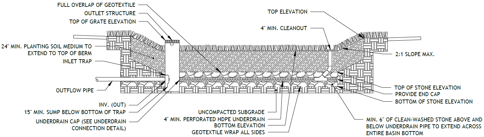
Figure 4.1‑5: Underdrain connection standard detail
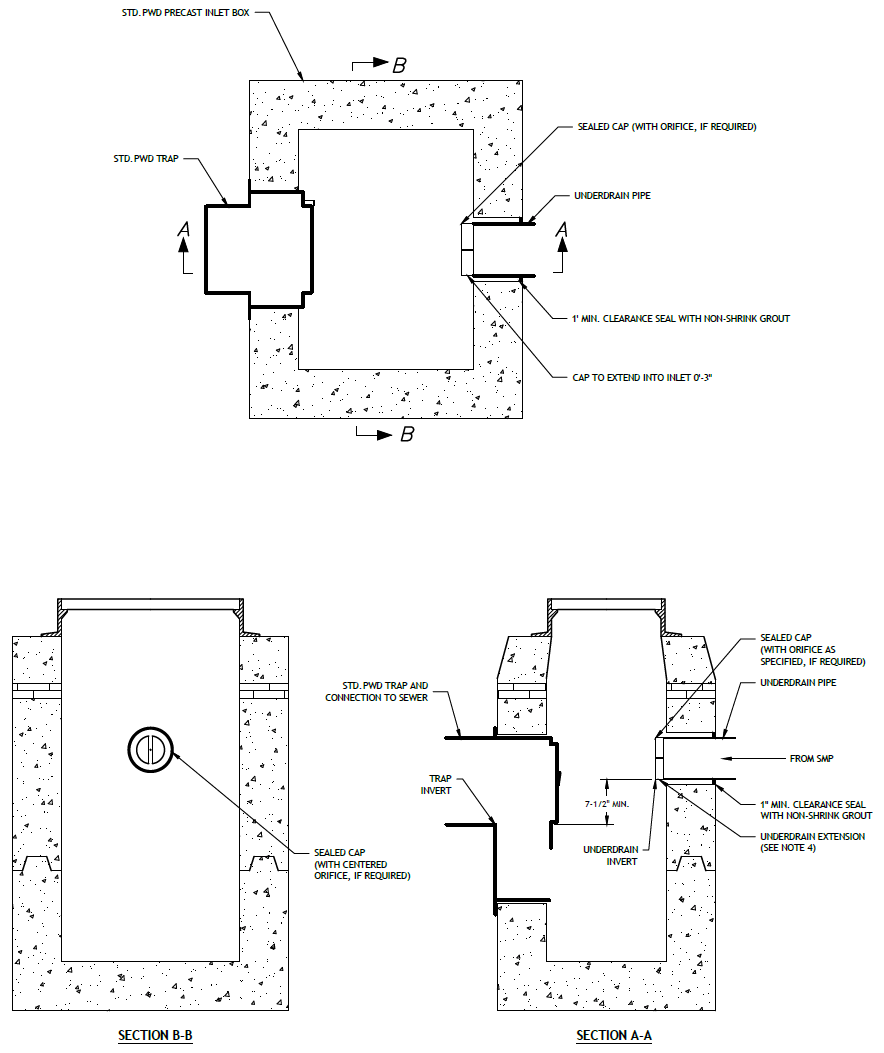
(The designer is referred to Appendix L to download Standard Detail CAD files.)
4.1.4 Bioinfiltration/bioretention material standards
Pretreatment material standards
- The designer is referred to Section 4.10, Pretreatment, for information on materials standards for pretreatment systems.
Inlet control material standards
- The designer is referred to Section 4.11, Inlet Controls, for information on material standards for inlet control systems.
Storage area material standards
- Stone designed for stormwater storage must be uniformly graded, crushed, clean-washed stone. PWD defines “clean-washed” as having less than 0.5% wash loss, by mass, when tested per American Association of State Highway and Transportation Officials (AASHTO) T-11 wash loss test. AASHTO No. 3 and No. 57 stone can meet this specification.
- Sand, if used, must be AASHTO M‑6 or American Society of Testing and Materials (ASTM) C‑33 sand and must have a grain size of 0.02 to 0.04 inches.
- Planting Soil Medium
- Planting soil should meet all the specifications listed below and should be a fertile, natural soil, free from large stones, roots, sticks, clods, plants, peat, sod, pockets of coarse sand, pavement and building debris, glass, noxious weeds including invasive species, infestations of undesirable organisms and disease-causing pathogens, and other extraneous materials harmful to plant growth.
- The texture of planting soil should conform to the classification within the United States Department of Agriculture triangle for Sandy Loam or Loamy Sand. Planting soil should be a mixture of sand, silt, and clay particles as required to meet the classification. Ranges of particle size distribution, as determined by pipette method in compliance with ASTM F-1632, are as follows:
- Sand (0.05 to 2.0 mm): 50 – 85%
- Silt (0.002 to 0.05mm): 40% maximum
- Clay (less than 0.002mm): 10% maximum
- Gravel (2.0 to 12.7 mm): 15% maximum
- Planting soil should be screened and free of stones larger than a half‑inch (12.7 millimeters) in any dimension. No more than 10% of the soil volume should be composed of soil peds greater than one inch.
- Clods, or natural clumps of soils, greater than three inches in any dimension should be absent from the planting soil. Small clods ranging from one to three inches and peds, natural soil clumps under one inch in any dimension, may be present but should not make up more than 10% of the soil by volume.
- The pH of the planting soil should have a range of 5.8 to 7.1.
- Soluble salts should be less than 2.0 mmhos/cm (dS/m), typically as measured by 1:2 soil-water ratio basic soil salinity testing. Sodic soils (Exchangeable Sodium Percentage greater than 15 and/or Sodium Adsorption Ratio greater than 13) are not acceptable for use regardless of amendment.
- Organic content of planting soil should have a range of 3% to 15% by weight, as determined by loss on ignition (ASTM D2974). To adjust organic content, planting soil may be amended, prior to placing and final grading, with the addition of organic compost.
- Mulch, if used, must be free of weeds and must consist of aged, double-shredded hardwood bark mulch or leaf mulch that has been shredded sufficiently to limit risk of matting, which can limit surface infiltration rates. For hydroseeding, paper mulch may be used. Approved mulching materials include organic materials such as compost, bark mulch, leaves, as well as small river gravel, pumice, or other inert materials. Grass clippings should not be used as mulch.
- Geotextile must consist of polypropylene fibers and meet the following specifications (AASHTO Class 1 or Class 2 geotextile is recommended):
- Grab Tensile Strength (ASTM-D4632): ≥ 205 lbs
- CBR Puncture Strength (ASTM-D6241): ≥ 500 lbs
- Flow Rate (ASTM-D4491): ≥ 95 gal/min/ft2
- UV Resistance after 500 hours (ASTM-D4355): ≥ 70%
- Tear Resistance (ASTM-D4533): ≥ 80 lbs
- Heat-set or heat-calendared fabrics are not permitted.
Vegetation material standards
- Trees and shrubs must be freshly dug and grown in accordance with good nursery practice.
- Perennials and herbaceous plants must be healthy, well-rooted specimens.
- A native grass/wildflower seed mix can be used as an alternative to groundcover planting. Seed mix must be free of weed seeds.
- Use of invasive plants is not permitted. All plants and trees must be appropriate and compatible with soil, hydrologic, light, and other site conditions. The designer is referred to Appendix I for plant lists.
Outlet control material standards
- Underdrains must be made of continuously perforated high-density polyethylene (HDPE) plastic piping with a smooth interior and a minimum inner diameter of four inches. HDPE pipe must meet the specifications of AASHTO M252, Type S or AASHTO M294, Type S.
- The designer is referred to Section 4.12, Outlet Controls, for more information on material standards for outlet control systems.
Inspection and maintenance access material standards
- Cleanouts must be made of material with a smooth interior having a minimum inner diameter of six inches. If the connecting pipe is eight inches in diameter or larger, then the cleanout must be eight inches in diameter.
4.1.5 Bioinfiltration/bioretention construction guidance
Careful consideration of issues like soil compaction, infiltration performance, and sediment control are critical to ensure proper bioinfiltration/bioretention functionality and reduce long-term maintenance needs. Poor oversight of construction activities could result in the need for substantial reconstruction to address performance problems.
- Provide erosion and sedimentation control protection on the site such that construction runoff is directed away from the proposed bioinfiltration/bioretention location. The designer is referred to the latest edition of the PA DEP Erosion and Sediment Pollution Control Program Manual for information on design standards for erosion and sedimentation control practices.
- Bioinfiltration areas must be physically marked prior to any land-disturbing activities to avoid soil disturbance and compaction during construction. Install construction fencing around bioinfiltration areas.
- Proposed bioretention areas may be used as sediment traps during construction. Bioinfiltration areas may not be used as sediment traps during construction, unless at least three feet of soil are left in place while the area is serving as a sediment trap and subsequently removed during construction after the contributing drainage areas have been stabilized.
- Complete site elevation grading and stabilize the soil disturbed within the limits of disturbance. Do not finalize bioinfiltration/bioretention excavation and construction until the drainage area is fully stabilized.
- Excavate bioinfiltration/bioretention area to proposed invert depth and manually scarify the in situ soils at the base of the excavation. Do not compact in situ soils. Heavy equipment must not be used within the bioinfiltration area. All equipment must be kept out of the excavated area to the maximum extent possible. The use of machinery to load any proposed stone from outside of the basin footprint is recommended. Rock construction entrances must not be located on top of areas proposed for infiltration practices. Heavy equipment exclusion zones must be established to avoid compaction of the infiltration area during construction. Excavate bioinfiltration/bioretention area to proposed invert depth and manually scarify the in situ soils at the base of the excavation. Do not compact in situ soils. Heavy equipment must not be used within the bioinfiltration area. All equipment must be kept out of the excavated area to the maximum extent possible. The use of machinery to load any proposed stone from outside of the basin footprint is recommended. Rock construction entrances must not be located on top of areas proposed for infiltration practices. Heavy equipment exclusion zones must be established to avoid compaction of the infiltration area during construction.
- Perform infiltration testing (if testing was deferred until construction). The designer is referred to Section 3.3 for guidance on infiltration testing procedures.
- For bioinfiltration SMPs, where infiltration is feasible, ensure underdrains are equipped with a water-tight end cap within the outlet control structure.
- For bioretention basins, where infiltration is infeasible, convert the underdrain to a flow-regulating underdrain by drilling an appropriately-sized orifice in the center of a water-tight underdrain cap center within the outlet control structure.
- Place impervious liner, if needed within a bioretention basin, ensuring continuous contact with subgrade. Extreme care should be taken during installation of a geomembrane liner so that no damage is done to any part of the material. Construction equipment, gasoline driven generators, or cans of gas or solvent must not be placed on the geomembrane material. The geomembrane material must not be used as a work area to prepare patches or to store tools and supplies. Temporary wind anchorage by means of sandbags or tires must be provided during geomembrane installation. Nails, rebar, wire ties, or other metal materials shall not be used to hold geomembrane in position. Geomembrane seaming must be performed in accordance with ASTM D7408 (PVC) and ASTM D8580 (LLDPE, PP). Non-destructive and destructive testing of geomembrane seaming must be performed in accordance with ASTM D7700. Mechanical attachment of geomembrane to pipe penetrations or structures must be installed in accordance with ASTM D6497/D6497M‑02. Placement of overlying material must be performed in a manner that will not damage the geomembrane. Excessive wrinkling of the geomembrane must be prevented prior to or while covering the geomembrane, ensuring no permanent folds or wrinkles in the liner. Any damage to the geosynthetic material must be repaired immediately.
- Any stone within the infiltration SMP must remain free of sediment and meet the washed stone specification found above. If sediment enters the stone, the contractor may be required to remove the sediment and replace with clean washed stone.
- Place filter fabric or pea gravel filter, then place the stone, and set the underdrain according to the plans.
- Backfill the excavated area as soon as the subgrade preparation is complete to avoid accumulation of debris. Place bioinfiltration/bioretention soil in 12- to 18‑inch lifts and tamp lightly by hand or compact by watering each lift. Ensure backfill process does not disrupt pipe placement and configuration. Slight overfilling might be necessary to account for settlement. Pre-soak the soil at least one day prior to final grading and landscaping to allow for settlement.
- After allowing for settlement, complete final grading within about two inches of the proposed design elevations, leaving space for top dressing of mulch or mulch/compost blend.
- Seed and plant vegetation as indicated on the plans and specifications.
- Place mulch and hand grade to final elevations.
- Install energy dissipaters as specified on the plans, if applicable.
- Water vegetation at the end of each day for two weeks after planting is completed.
- Water vegetation regularly during first year to ensure successful establishment.
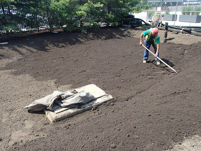
An example of a bioinfiltration basin installation in Philadelphia 4.1.6 Bioinfiltration/bioretention maintenance guidance
Bioinfiltration/bioretention maintenance activities focus largely on maintaining infiltration capacity and the health of vegetation. During periods of extended drought, bioinfiltration/bioretention SMPs may require watering approximately every ten days.
General recommended maintenance activities for bioinfiltration/bioretention SMPs are summarized in Table 4.1‑5 below
Table 4.1‑5: Bioinfiltration/bioretention maintenance guidelines
Early maintenance activity Frequency Water vegetation at the end of each day for two weeks after planting is completed. Daily for two weeks after installation Water vegetation regularly to ensure successful establishment after planting. Every four days during periods of four or more days without rain, June through August for the first year after installation Inspect vegetation for signs of disease or distress. Biweekly for the first year after installation Inspect inlet controls, outlet structures, and storage areas for trash and sediment accumulation. Monthly for the first year after installation to determine ongoing maintenance frequency Ongoing maintenance activity Frequency Remulch void areas. As needed Treat diseased trees and shrubs. As needed Keep overflow free and clear of leaves. As needed Remove any invasive vegetation by hand. As needed Thin any overgrown areas of vegetation. As needed Inspect soil and repair eroded areas. Monthly Remove litter and debris. Monthly Clear leaves and debris from overflow. Monthly Empty filter bags for pretreatment devices. Ensure filter bag is installed properly. Monthly Inspect trees and shrubs to evaluate health, replacing if necessary. Quarterly Inspect underdrain cleanouts. Quarterly Ensure river rock layout is sufficient to dissipate flow and check for downstream erosion. Replace river rock as necessary and repair erosion issues. Quarterly Add additional mulch. Quarterly Inspect for sediment build-up, erosion, and vegetative conditions. Remove sediment buildup, stabilize eroded areas and add vegetation if necessary. Quarterly Evaluate the drain down time of the SMP after a storm of at least one inch in no more than 24‑hours to ensure an SMP drain down time of less than 72 hours. Ongoing Maintain records of all inspections and maintenance activity. Ongoing The designer is referred to Section 4.10, Pretreatment, Section 4.11, Inlet Controls, Section 4.12, Outlet Controls, and Section 4.13, Landscaping, for information on maintenance guidance for pretreatment, inlet controls, outlet controls, and landscaping.
-
4.2 Porous Surfaces
Download summaries of this SMP and its maintenance guidance, with quick reference information for clients and developers:
4.2.1 Porous surface introduction
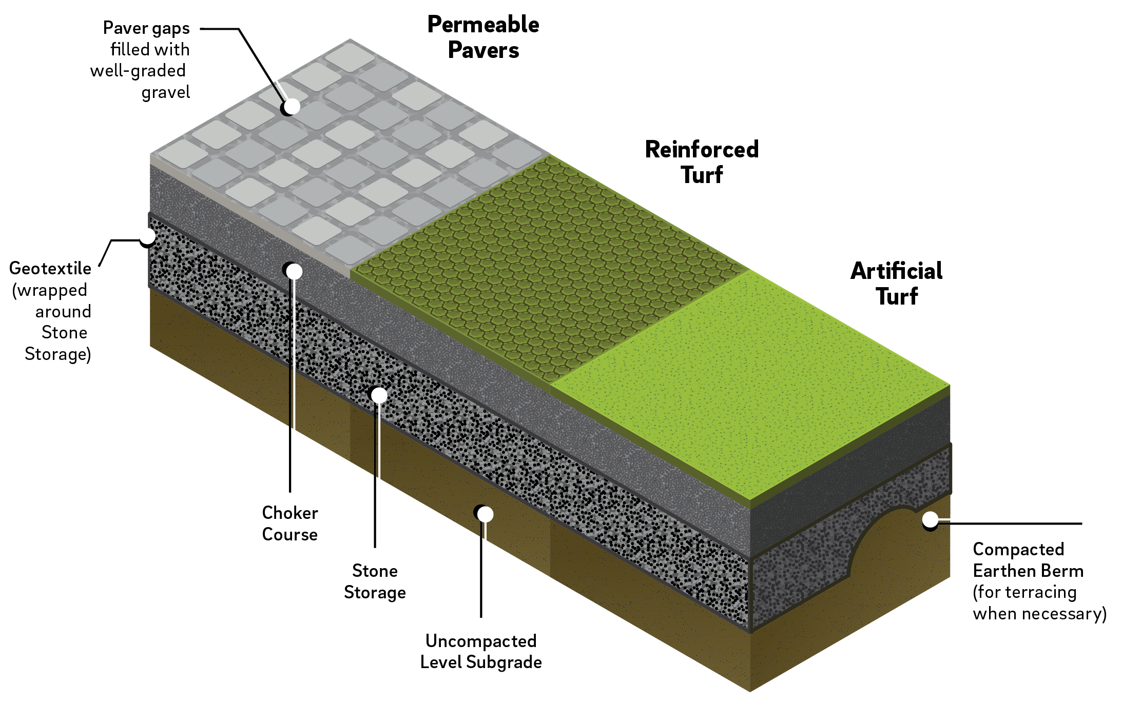
Porous surfaces can provide surface-level structural support while allowing stormwater to drain directly through the surface into an underlying stone bed and the soil below, thereby reducing surface stormwater runoff. Permitted porous surfaces include, but are not limited to, permeable pavers, reinforced turf, artificial, or synthetic, turf, and porous safety surfaces. (Porous asphalt, porous concrete, and resin-bound aggregate are strictly prohibited.) Interlocking pavers have openings filled with stone to create a porous surface. For all these types, stormwater flows through the porous surface during a rain event, then drains into the subbase, where it is stored until it infiltrates into the soil.
Porous surfaces can be combined with other SMPs in series to meet the Stormwater Regulations. The designer is referred to Section 3.2.3 for information on using SMPs in series.
Design of porous surfaces is not limited to the examples shown within this text. Successful stormwater management plans will combine appropriate materials and designs specific to each site.
Porous surface design may be considered differently for Stormwater Retrofits. Designers looking to incorporate porous surface in Stormwater Retrofit projects should contact Stormwater Billing and Incentives for additional information.
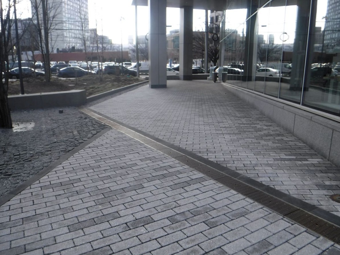
An example of permeable pavers in Philadelphia When can porous surfaces be used?
Porous surface is only suitable for select types of development. Porous surfaces can be particularly well-suited for walkways, sidewalks, athletic surfaces, and playgrounds. Its footprint can be adapted to fit into spaces of almost any size and can be integrated into many different site layouts.
Porous surface can be designed to meet the traffic loading requirements for most parking lots and travel surfaces, but the maintenance costs are significantly increased in areas that receive high traffic volume. For example, commercial parking lots will require more frequent vacuuming to prevent the surface from clogging.
Key advantages of porous surfaces
- Can be used in place of traditional paved surfaces
- Can fit into spaces of almost any size and be integrated into many different site layouts
- Can be used as DIC to reduce DCIA as an alternative to traditional hardscape surfaces
- Reduces ponding and icing that can be associated with traditional hardscape surfaces
- Provides ancillary benefits such as better conditions for trees and reduced heat island effect
- Permeable pavers, reinforced turf, artificial turf, and porous safety surfaces are eligible for inclusion in an Expedited Post‑Construction Stormwater Management Plan (PCSMP) Review project
Key limitations of porous surfaces
- Not recommended for high traffic loading areas or on heavy industrial sites where vehicles or equipment may contribute heavy sediment or gross pollutant loads to porous surfaces
- Typically, not suitable for steep slope applications
- Requires frequent maintenance with specialized equipment to maintain performance
- May degrade more rapidly if located in areas with frequent vehicular turning
Key design considerations for porous surfaces
- Design of paving sections must consider system stability based on anticipated structural loading.
- Porous surfaces should not be placed downstream of large impervious or pervious areas.
- Runoff from adjacent impervious and pervious areas must be conveyed directly to the subsurface storage to prevent clogging of porous surfaces.
- Porous surfaces should not be used in areas where gasoline or other hazardous materials may be dispensed or handled.
- For any porous surface structural SMP that discharges onto an adjacent property, a drainage easement may be required and is recommended.
Porous surface types
Porous surface systems can be distinguished by their intended stormwater management objective.
Porous surface DIC systems are designed to receive and infiltrate direct (1:1) rainfall only and are considered as DIC. Infiltration testing is not required for porous surface DIC; however, it is recommended to ensure timely drainage of the stone base. In some cases, where a small amount of run-on cannot be avoided, it may still be possible to consider the porous surface disconnected. Such allowances will be considered on a case-by-case basis by PWD.
Porous surface over a structural SMP is considered an SMP in series, where the porous surface is designed to manage its direct (1:1) rainfall, and the structural SMP beneath it is designed to store and manage DCIA runoff from other areas on-site in addition to direct (1:1) rainfall onto the porous surface atop the SMP. The porous surface cannot receive the additional runoff; The additional runoff must be conveyed directly to the underlying SMP. Porous surface that receives direct overland flow is extremely prone to clogging. Porous surface over a structural SMP is essentially a subsurface infiltration or detention system (based on infiltration feasibility) with a porous surface at-grade. The porous surface over the structural SMP footprint is considered DCIA. The structural SMP requires infiltration testing. The designer is referred to Section 3.3 for information on infiltration testing.
Porous surface systems can also be distinguished by the type of porous paving surface. There are many different types of structural surfaces that allow water to flow through void spaces in the surface. Any of these alternatives serve as a form of conveyance and filtration for the storage bed below. Several of the most commonly used porous structural surfaces are described below, but this does not represent an exhaustive list of the porous surfaces appropriate for stormwater management applications.
Permeable pavers are typically interlocking units (often concrete) with openings that can be filled with a pervious material such as gravel. These units are often implemented for aesthetic reasons and are especially well suited to plazas, patios, residential driveways, and small parking areas. There are also plastic grids that can be filled with gravel to create a fully gravel surface that is not as susceptible to rutting and compaction as are traditional gravel lots. Gravel used in interlocking concrete pavers or plastic grid systems must be well-graded to ensure permeability.
Reinforced turf consists of interlocking structural units with openings that can be filled with soil for the growth of turf grass and are suitable for traffic loads and parking. They are often used in overflow or event parking. Reinforced turf grids can be made of concrete or plastic and are underlain by a stone and/or a sand drainage system for stormwater management. While both plastic and concrete units perform well for stormwater management and traffic needs, plastic units may provide better turf establishment and longevity, largely because the plastic will not absorb water and diminish soil moisture conditions.
Artificial, or synthetic, turf is a water permeable surface of synthetic fibers that emulates the aesthetic of natural grass. First gaining popularity in the 1960s, artificial turf has undergone a number of changes to its standard composition, with the most widely-used systems today featuring infills that are mixtures of sand and recycled (“crumb”) rubber. The designer is referred to Section 3.5.5 for more information on athletic turf fields.
Porous asphalt, porous concrete, and resin-bound aggregate are strictly prohibited. Property owners with existing systems comprised of any of these surface types are referred to Section 4.2.6 for Maintenance Guidance.
4.2.2 Porous surface components
Figure 4.2‑1: Porous surfaces with typical features
Pretreatment component
Porous surface does not typically have pretreatment systems due to its (1:1) loading ratio. Run-on from pervious or impervious areas is not permitted, so pretreatment is not necessary. However, any SMP installed beneath a porous surface does require pretreatment of the runoff conveyed directly to it via piping.
Pretreatment systems capture trash, sediment, and/or pollutants from stormwater runoff before delivery to the storage or infiltration area. Pretreatment needs will vary significantly depending on the contributing drainage area composition and use. Pretreatment can include structures such as sumped and trapped inlets, sediment/grit chambers or separators, media filters, inlet inserts, or other appropriate prefabricated or proprietary designs to remove sediment, floatables, and/or hydrocarbons from stormwater runoff prior to being conveyed to a porous surface structural SMP. While inlet hoods are preferred, permanent filter bags may be accepted for Stormwater Retrofit projects where existing inlets do not have hoods and inlet reconstruction is not feasible. In addition to sumped and trapped inlets, permanent filter bag inserts are required for sites that generate pollutants such as loading docks, material storage facilities, junk yards, and waste collection and disposal sites. Permanent filter bags will require frequent cleanings.
Pretreatment can also consist of filter strips, forebays, and swales. The designer is referred to Section 4.10 for more information on pretreatment systems.
Inlet control component
Porous surface DIC systems, which receive direct (1:1) rainfall only, do not have inlet controls. For porous surface over structural SMPs, inlet control systems convey and control the flow of stormwater from the contributing catchment area directly to the structural SMP.
Inlet control needs will vary depending on the design of stormwater conveyance systems and the site layout. The designer is referred to Section 3.4.2 for guidance on stormwater conveyance system design.
Inlet controls may include flow splitters, curbless design/curb openings, energy dissipaters, and inlets. The designer is referred to Section 4.11 for more information on inlet controls.
Storage area component
Storage areas within porous surface DIC systems temporarily hold stormwater runoff as it infiltrates into native soils.
The subsurface storage component of a porous surface structural SMP is typically constructed of a stone-filled, level-bottomed bed or trench, which may or may not incorporate pipes, arches, concrete vaults, crates, plastic grids, or other proprietary structures. The void spaces between the stones and/or structures store stormwater until it can infiltrate into the surrounding soils or be released downstream at a controlled rate.
Outlet control component
Outlet controls within a porous surface structural SMP can provide a range of functions, including the following:
- Controlling how much water is stored for infiltration, if infiltration is feasible;
- Meeting drain down time requirements;
- Controlling the rate of discharge from the system and limiting water surface elevations during various storm events; and/or
- Bypassing of flows from large storm events.
Positive overflow must be provided for porous surfaces. Positive overflow conveys runoff from larger storms out of the system and prevents flooding. In most cases, specifically for porous surface DIC, appropriate grading of the porous surface is sufficient for providing positive flow away from porous surface should it become clogged or ineffective. For larger porous surface systems or porous surface over a structural SMP, inlets are the most common overflow. A perforated pipe system can convey water from the storage bed, but static storage for the Water Quality Volume (WQv) is required below the perforated pipes.
Outlet controls may include orifices, weirs, or underdrains. The designer is referred to Section 4.12 for more information on outlet controls.
Inspection and maintenance access component
Safe and easy inspection and maintenance access to all major components within porous surface is critical to ensuring long-term performance. Inspection and maintenance access structures provide a portal to any structural SMP beneath the porous surface. Access points provide access to subsurface systems, both for inspections and routine maintenance, and for pumping water out of subsurface systems in cases of failure or severe damage. Manholes provide access for maintenance personnel and equipment to perform maintenance and inspections. Cleanouts provide access for hoses and vacuum equipment, as well as for any installed underdrains. Observation wells provide access to the bottom of subsurface systems for performance inspections and monitoring. Access structures may also serve additional functions, such as joining subsurface pipes.
4.2.3 Porous surface design standards
General design standards
- For porous surface DIC systems:
- A reduction in DCIA is permitted when a porous surface system is installed on-site such that it does not create any areas of concentrated infiltration or discharge.
- The surface slope in any direction across porous surface cannot exceed 5% to be eligible for disconnection credit.
- The choker course depth must be a minimum of two inches.
- If an underdrain is proposed, the porous surface will only be considered DIC if the first 1.5 inches of runoff can be stored below the lowest invert of the underdrain.
- Appropriate Curve Number (CN) values must be used when performing Flood Control calculations.
- For porous surfaces over structural SMPs, if infiltration is feasible, the designer is referred to Section 4.4 for subsurface infiltration general design requirements.
- For porous surfaces over structural SMPs, if infiltration is infeasible, the designer is referred to Section 4.8 for subsurface detention general design requirements.
Pretreatment design standards
- Acceptable form(s) of pretreatment must be incorporated into design. Pretreatment of runoff from all inlets is required. At a minimum, this can be achieved through the use of sumps and traps for inlets, and sump boxes with traps downstream of trench drains. The designer is referred to Section 4.10 for more information on design standards for pretreatment systems.
Inlet control design standards
- The designer is referred to Section 4.11 for information on design standards for inlet control systems.
Storage area design standards
- For porous surface DIC systems:
- Stone storage bed depth must be a minimum of eight inches, except when located beneath walkways or play surfaces, for which a depth of four inches is allowable.
- Stone must be separated from soil media by a separation barrier, such as a geotextile or a pea gravel filter, to prevent sand, silt, and sediment from entering the system.
- Stone storage systems must have a level bottom. Terraced systems may be used to maintain a level infiltration interface with native soil while accommodating significant grade changes.
- For porous surfaces over structural SMPs, if infiltration is feasible, the designer is referred to Section 4.4 for subsurface infiltration storage area requirements.
- For porous surfaces over structural SMPs, if infiltration is infeasible, the designer is referred to Section 4.8 for subsurface detention storage area requirements.
- When SMPs are used in series, the storage areas for all SMPs must provide cumulative static storage for the WQv, but there is no minimum storage requirement for each individual SMP used in series.
Outlet control design standards
- Impervious liners beneath porous surfaces should be avoided, but they may be necessary in areas over tunnels or subsurface structures. The lined area should be a minimal portion of the total porous area. If a significant area needs to be lined, a porous surface may not be an appropriate management strategy.
- Underdrains, if proposed for porous surface DIC systems, must meet the following requirements:
- Underdrains must be surrounded by a sand or stone layer to filter sediment and facilitate drainage.
- The minimum allowable thickness of a sand or stone filter layer is six inches both above and beneath the underdrain.
- To prevent clogging, underdrain pipes must be surrounded by a geotextile fabric if a sand layer is used.
- Inlets or area drains must be provided for all porous surface areas in excess of 5,000 square feet, in order to provide positive overflow.
- The designer is referred to Section 4.12 for information on design standards for outlet control systems.
Inspection and maintenance design standards for porous surfaces over a structural SMP
- Cleanouts, manholes, access panels and other access features must be provided to allow unobstructed and safe access to SMPs for routine maintenance and inspection of inflow, outflow, underdrains, and storage systems.
- Observation wells must be provided for SMPs that include stone storage and must meet the following requirements:
- The observation well must be placed at the invert of the stone bed.
- The observation well must be located near the center of the stone bed system to monitor the level and duration of water stored within the SMP (drain down time). A minimum of six inches of clearance must be provided between the edge of the observation well’s concrete ring or frame and any nearby site features (curbing, tree pits, sidewalk edge, etc.). Plan view dimensioning for the proposed location of the observation well, relative to the boundaries of the SMP it lies within, must be provided on the plans.
- Adequate inspection and maintenance access to the observation well must be provided.
- An observation well located in a paved area must be outfitted with a cover and frame. The cover plate must be installed flush with the surrounding surface at finished grade, and grading should drain away from the observation well wherever possible. The solid section of the observation well must extend into the cover frame enough such that a bentonite/cement seal can be placed around the well within the frame, and a solid slip-on cap can be fitted onto the pipe end.
- An observation well located in an unpaved area must have a concrete ring or frame poured for support, with three lengths of rebar evenly spaced around the ring and three inches from its outer edge. The observation well should be located outside of the ponding area of any surface SMPs. If, due to space limitations, an observation well must be placed in the ponding area of a surface SMP, the concrete ring and well cover must extend three inches above the SMP’s maximum ponding depth.
- The observation well must include a slotted section within the storage layer of the SMP. The top of the slotted well section must extend to a minimum of six inches below the top of the SMP storage layer, and the slotted section must extend down the entire depth of the SMP.
- Access features for underground storage systems
- Access features must be provided for all underground storage systems that are not stone storage beds.
- A sufficient number of access points in the system must be provided to efficiently inspect and maintain the storage area.
- For cast-in-place vault systems, access features must consist of manholes or grated access panels or doors. Grated access panels are preferred to maintain airflow.
- For grid storage or other manufactured systems, follow the manufacturer’s recommendations.
- Ladder access is required for vaults greater than four feet in height.
- Header pipes, at minimum 36‑inch diameter, connected to manholes at each corner of the subsurface system must be provided. Alternatively, smaller header pipes may be used if cleanouts are provided on the manifold/header pipe junction for each distribution pipe. The cleanouts must be on alternating sides of the SMP.
Figure 4.2‑2: Porous surfaces standard detail
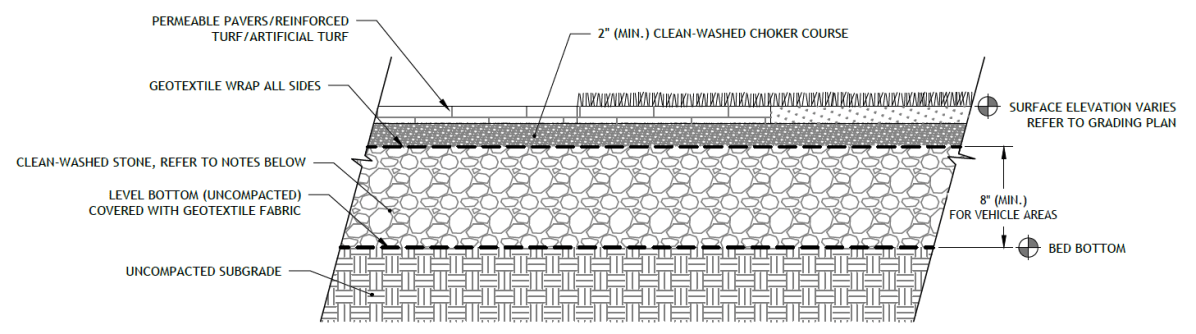
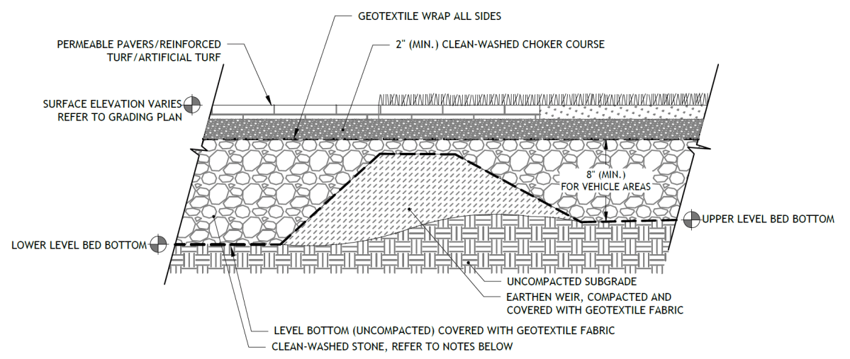
Figure 4.2‑3: Terraced porous surfaces standard detail
(The designer is referred to Appendix L to download CAD files or PDF file versions.)
4.2.4 Porous surface material standards
Pretreatment material standards
- The designer is referred to Section 4.10 for information on materials standards for pretreatment systems.
Inlet control material standards
- Permeable Pavers and Reinforced Turf Grid Systems
- Permeable paver and grid systems must conform to manufacturer specifications.
- The systems must have a minimum flow through rate of five inches per hour and a void percentage of no less than 10%.
- Gravel used in interlocking concrete pavers or plastic grid systems must be well-graded and washed to ensure permeability.
- The designer is referred to Section 4.11 for information on material standards for inlet control systems.
Storage area material standards
- Stone
- Stone designed for stormwater storage must be uniformly graded, crushed, clean-washed stone. PWD defines “clean-washed” as having less than 0.5% wash loss, by mass, when tested per AASHTO T-11 wash loss test. AASHTO No. 3 and No. 57 stone can meet this specification.
- All aggregates used within a porous surface system must meet the following requirements:
- Maximum wash loss: 0.5% per AASHTO T-11
- Minimum durability index: 35 per ASTM D3744
- Maximum abrasion: 10% for 100 revolutions and 50% for 500 revolutions per ASTM C131
- All choker course aggregate must meet the specifications of AASHTO No. 57 and must meet the following gradation:
Table 4.2‑1: Required choker course gradation
U.S. standard sieve size Percent passing by weight 1 ½” (37.5 mm) 100% 1” (25 mm) 95–100% ½” (19 mm) 25–60% #4 (4.75 mm) 0–10% #8 (2.36 mm) 0–5% - Sand, if used, must be AASHTO M‑6 or ASTM C‑33 sand and must have a grain size of 0.02 to 0.04 inches.
- Storage Chambers (For Porous Surface Structural SMPs)
- Pipe used within a subsurface infiltration SMP must be continuously perforated and have a smooth interior with a minimum inside diameter of four inches.
- High-density polyethylene (HDPE) pipe must meet the specifications of AASHTO M252, Type S or AASHTO M294, Type S.
- Any pipe materials outside the SMP are to meet City Plumbing Code Standards.
- Geotextile must consist of polypropylene fibers and meet the following specifications (AASHTO Class 1 or Class 2 geotextile is recommended):
- Grab Tensile Strength (ASTM-D4632): ≥ 205 lbs
- CBR Puncture Strength (ASTM-D6241): ≥ 500 lbs
- Flow Rate (ASTM-D4491): ≥ 95 gal/min/ft2
- UV Resistance after 500 hours (ASTM-D4355): ≥ 70%
- Tear Resistance (ASTM-D4533): ≥ 80 lbs
- Heat-set or heat-calendared fabrics are not permitted.
Outlet control material standards
- Underdrains, if proposed, must be made of continuously perforated HDPE plastic piping with a smooth interior and a minimum inner diameter of four inches. HDPE pipe must meet the specifications of AASHTO M252, Type S or AASHTO M294, Type S.
- The designer is referred to Section 4.12 for information on material standards for outlet control systems.
Inspection and maintenance access material standards
- Observation wells
- The observation well must consist of slotted plastic pipe with minimum inner diameter of four inches and a solid cap at the surface. The slotted section of the well must consist of PVC slotted well screen with 0.01‑inch slot size and an attached perforated PVC cap at the bottom.
- The observation well’s cover must be ductile iron in a gray iron frame.
- For an observation well located in an unpaved area, the well’s concrete ring must be a minimum of six inches wider in any dimension than the cover frame, of equal depth as the cover frame itself, and poured atop a minimum of six inches of AASHTO #57 stone bedding. A frame conforming to these minimum dimensions may be circular or square.
- Cleanouts must be made of material with a smooth interior having a minimum inner diameter of six inches. If the connecting pipe is eight inches in diameter or larger, then the cleanout must be eight inches in diameter.
4.2.5 Porous surface construction guidance
The construction guidelines herein apply to all porous surface systems. Proper construction and careful consideration of soil compaction, infiltration performance, and sedimentation control of subsurface infiltration systems are essential to ensure long-term functionality and reduce long-term maintenance needs. Since subsurface infiltration systems are, by definition, buried, construction oversight is critical. At a minimum, verification of volumes, grades, and elevations must be confirmed prior to backfill.
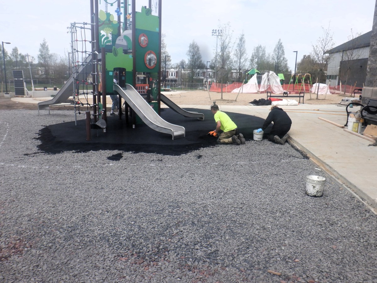
An example of a porous safety surface installation in Philadelphia - Areas for porous surface systems must be clearly marked before any site work begins to avoid soil disturbance and compaction during construction.
- Excavate subsurface area to proposed depth. Excavation should take place after contributing upstream disturbed areas have been permanently stabilized. If this is impractical, install PWD-approved erosion and sedimentation control Best Management Practices (BMPs) to prevent runoff and sediment from entering the excavated bed. Where erosion of subgrade has caused accumulation of fine materials and/or surface ponding, this material must be removed with light equipment and the underlying soils scarified to a minimum depth of six inches with a York rake or equivalent and light tractor.
- Existing subgrade must not be compacted, and construction equipment traffic must be minimized prior to placement of the geotextile and stone bed. The use of machinery to load stone from outside of the basin footprint is recommended. If it is essential that equipment be used in the excavated area, all equipment must be approved by the engineer. Equipment with narrow tracks or tires, rubber tires with large lugs, or high-pressure tires will cause excessive compaction and must not be used. Should the subgrade be compacted during construction, additional testing of soil infiltration rates and system redesign may be required. Rock construction entrances must not be located on top of areas proposed for infiltration practices.
- Bring subgrade of stone infiltration bed to line, grade, and elevations indicated in the drawings, while avoiding compaction. The bottom of the infiltration bed must be at a level grade.
- Place geotextile and recharge bed aggregate immediately after approval of subgrade preparation to prevent accumulation of debris or sediment. Aggregate installation should take place after contributing upstream disturbed areas have been permanently stabilized. Install PWD-approved erosion and sedimentation control BMPs to prevent runoff and sediment from entering the storage bed during the placement of the geotextile and aggregate bed.
- Place geotextile in accordance with manufacturer’s standards and recommendations. Adjacent strips of filter fabric must overlap a minimum of 16 inches. Fabric must be secured at least four feet outside of bed. This edge strip should remain in place until all bare soils contiguous to beds are stabilized and vegetated. As the site is fully stabilized, excess geotextile can be cut back to the edge of the bed.
- Install aggregate course in lifts of six to eight inches. Compact each layer with equipment, keeping equipment movement over storage bed subgrades to a minimum. Install aggregate to grades indicated on the drawings.
4.2.6 Porous surface maintenance guidance
Maintenance of porous surfaces focuses on the periodic removal of sediment and debris from the system. While porous asphalt, porous concrete, and resin-bound aggregate are no longer permitted, maintenance guidance for existing systems can be found below. General recommended maintenance activities for porous surfaces are summarized in Table 4.2‑2.
Table 4.2‑2: Porous surface maintenance guidelines
Early maintenance activity Frequency Inspect erosion control and flow spreading devices until soil settlement and vegetative establishment of contributing areas has occurred. Biweekly Ongoing maintenance activity Frequency Inspect erosion control and flow spreading devices until soil settlement and vegetative establishment of contributing areas has occurred. Biweekly Mow grass in permeable paver or reinforced turf grid systems that have been planted with grass. As needed Replace filter bags for pretreatment devices. Please ensure filter bags are installed properly. Quarterly Vacuum porous asphalt or concrete surfaces on grandfathered projects with regenerative air sweeper or commercial vacuum sweeper (traditional street sweepers are not appropriate). Semiannually Vacuum inlet structures within or draining to the structural SMP beneath the porous surface. Semiannually Inspect underdrain cleanouts, if any. Semiannually Maintain records of all inspections and maintenance activity. Ongoing Sediment control
Superficial soil does not necessarily clog the voids in porous surfaces. However, soil that is ground in repeatedly by tires can lead to clogging. Therefore, trucks or other heavy vehicles should be prevented from tracking or spilling soil onto the porous surface. Furthermore, all construction or hazardous materials carriers should be prohibited from entering a porous surface lot. Areas with heavy vehicular traffic will require more frequent vacuuming.
Winter maintenance
Winter maintenance for a porous surface may be necessary but is usually less intensive than that required for a standard pavement lot. By its very nature, a porous surface system with subsurface aggregate bed may have better snow and ice melting characteristics than standard pavement. Once snow and ice melt, they flow through the porous surface rather than refreezing. Therefore, ice and light snow accumulation are generally not as problematic. However, snow will accumulate during heavier storms. Abrasives such as sand or cinders must not be applied on or adjacent to the porous surface. Snow plowing is acceptable, provided it is done carefully (i.e., by setting the blade about 0.5 inches higher than usual and using a rubberized blade or blade tip). Salt is acceptable for use as a deicer on the porous surface, though non-toxic, organic deicers, applied either as blended, magnesium chloride-based liquid products or as pretreated salt, are preferable. Any deicing materials should be used in moderation.
Repairs
Potholes are not common; though settling might occur if a soft spot in the subgrade is not removed during construction. Damaged areas that are smaller than 50 square feet and comprising less than 10% of the total porous area can be patched, depending on the location within the porous area. In many cases the loss of porous surface will be insignificant. If an area greater than 50 square feet or 10% of the total is in need of repair, approval of patch type must be sought from either the engineer or owner. Porous surfaces must never be seal coated under any circumstances. Any required repair of drainage structures should be done promptly to ensure continued proper functioning of the system.
Outlet controls
The designer is referred to Section 4.12 for information on maintenance guidance for outlet controls.
-
4.3 Green Roofs
Download summaries of this SMP and its maintenance guidance, with quick reference information for clients and developers:
4.3.1 Green roof introduction
Green roofs, also referred to as vegetated roofs, eco-roofs, and roof gardens, consist of a layer of vegetation that covers an otherwise conventional flat or moderately pitched roof. A green roof is composed of multiple layers that may include a moisture interception layer/geotextile, drainage layer, engineered growing medium, and vegetation above the roofing system and its waterproofing membrane. Through the appropriate selection of materials, green roofs can provide runoff volume reduction and runoff peak rate attenuation.
Green roofs can be combined with other stormwater management practices (SMPs) in series to meet the Philadelphia Water Department (PWD) Stormwater Regulations (Stormwater Regulations). The designer is referred to Section 3.2.3, for information on using SMPs in series.
Green roofs may be partially paved, where property owners wish to include occupiable space within the green roof. The designer is referred to Section 4.3.3, for information on green roofs with paving, or decks where runoff is tributary to and managed by the adjacent vegetated roof.
The design of green roofs is not limited to the examples shown within this text. Successful stormwater management plans will combine appropriate materials and designs specific to each site.
Green roof design may be considered differently for Stormwater Retrofits. Designers looking to incorporate green roofs in Stormwater Retrofit projects should contact Stormwater Billing and Incentives for additional information.
A green roof is an excellent stormwater management option on a fully built-out or highly-constrained site. They can be installed on many types of roofs, including terraces, high-rise building roofs, and low-podium or at-grade on-structure installations. Roofs with pitches up to 2:12 (16.7%) can, in most instances, accommodate green roofs without special slope stabilization provisions.
Green roofs can also be installed as a Stormwater Retrofit on existing buildings with flat, mildly sloped, or terraced roofs after confirmation of adequate structural loading capacity, waterproofing, and protection of rooftop utilities.
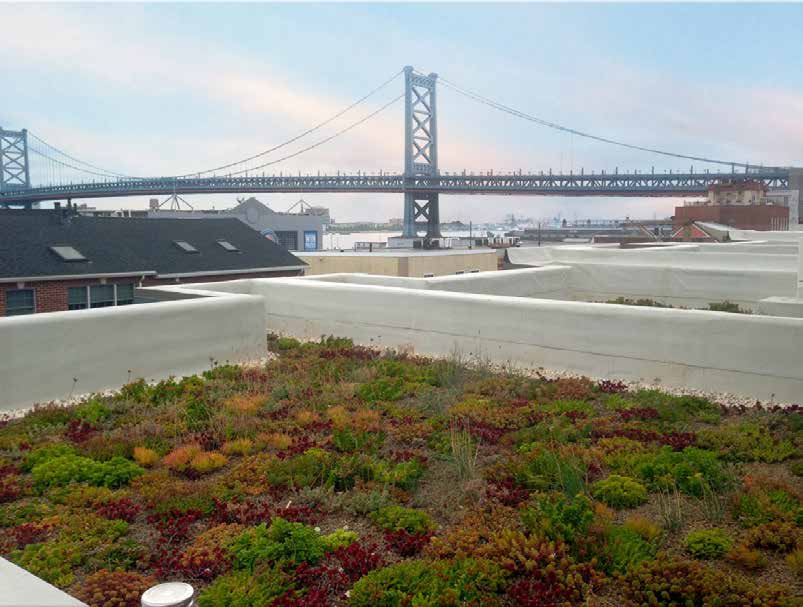
An example of a green roof in Philadelphia Where can green roofs be used?
A green roof is an excellent stormwater management option on a fully built-out or highly constrained site. They can be installed on many types of roofs, including terraces, high-rise building roofs, and low-podium or at-grade on-structure installations. Roofs with pitches up to 2:12 (16.7%) can, in most instances, accommodate green roofs without special slope stabilization provisions.
Green roofs can also be installed as a Stormwater Retrofit on existing buildings with flat, mildly sloped, or terraced roofs after confirmation of adequate structural loading capacity, waterproofing, and protection of rooftop utilities.
Tax Credit
Installation of a green roof may also qualify a project for a Business Income and Receipts Tax (BIRT) Credit!
Key advantages of green roofs
- Manage stormwater runoff without occupying surface-level space
- Well-suited for sites at which roofs make up a large fraction of the total impervious area and for sites with ground-level space constraints
- Typically require no additional sewer connections besides those already provided for the building
- Promote the retention, slow release, and evapotranspiration of precipitation
- Enhance building aesthetics and market value
- Help regulate building temperature in both the summer and winter, thus reducing cooling and heating costs
- Reduce urban heat island effect by providing evaporative cooling
- Can improve air quality by filtering particulate matter
- Extend the service life of the roof by protecting the underlying roof membrane from mechanical damage, shielding it from UV radiation, and buffering temperature extremes
- Require no excavation
- Can be designed to provide spaces for recreation, supplement bird habitat, developing educational resources, and creating new opportunities for urban food production
- Provide educational benefits, especially when used at public and/or highly visible sites such as schools, recreation centers, libraries, etc.
- Assume less risk for projects within the floodplain
- Eligible for inclusion in an Expedited Post‑Construction Stormwater Management Plan (PCSMP) Review project
Key limitations of green roofs
- May need to be combined with other SMPs to meet the Flood Control requirement
- More expensive to install than most conventional roofs
- May have limited Stormwater Retrofit feasibility for existing buildings and structures due to structural capacity issues
Key design considerations for green roofs
- Coordination of green roof design with the design of building heating, ventilation, and air conditioning (HVAC) systems can help to maximize operational cost savings. For example, some research suggests that green roofs can improve building energy efficiency by lowering the temperature of air at the intakes for climate control systems.
- Stormwater management effectiveness can be improved by introducing measures to enhance evapotranspiration. Typical expedient measures include:
- Introducing low-transmissivity drainage layers;
- Lengthening seepage pathways to drains;
- Introducing rainfall interception layers;
- Selecting plants with dense root habits; and
- Selecting growing medium with high water-holding capacity.
- For extensive green roofs (green roofs six inches thick or less), a large proportion of the initial planting should be varieties of sedums. Sedums may be interplanted or installed as a ground cover in coordination with other species. To ensure diversity and viability, at least six different species or cultivars of sedum should be used, including two genera (i.e., both Sedum and Phedimus species). The remainder of plants may be herbs, meadow grasses, or meadow flowers, depending on the desired appearance.
- Plant diversity and coverage are more significant for stormwater performance than specific species type (note that species selections remain important from a habitat and ecosystems perspective). Long-term species selection is flexible provided the plant cover is continuous, the root masses are persistent, and:
- Green roof plant management should emphasize continuous plant cover to maximize effectiveness of rainfall interception and minimize the potential for wind erosion, particularly in the winter months. Plant combinations that include meadow-type native grasses and wildflowers may reduce weed pressures when mature. Species must not be invasive.
- For stormwater management purposes, artificial, or synthetic, turf surfaces are not considered green roofs and must be combined with other SMPs.
- For any green roof that discharges onto an adjacent property, a drainage easement may be required and is recommended.
Green roof types
There are two types of green roofs. An extensive green roof is a thin (usually less than six inches), lightweight system that is typically predominantly planted with succulents, drought-tolerant perennials, and drought-tolerant grass. An intensive green roof is a deeper (typically greater six inches or greater), heavier system designed to sustain complex landscapes. Intensive green roofs offer a wider range of stormwater design options, including blue‑green roofs (Section 4.14) and similar designs with roof drain restrictors that retain water in the base of the profile for subsequent plant transpiration.
4.3.2 Green roof components
Figure 4.3‑1: Green roof with typical features
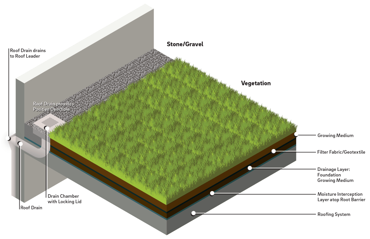
Figure 4.3‑2: Partially paved green roof with typical features
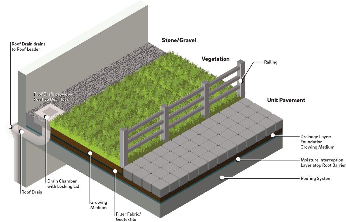
Inlet control component
Green roofs that only receive direct (1:1) rainfall do not have inlet controls. For green roofs that receive runoff from roof directly connected impervious area (DCIA), distribution piping may be provided to evenly disperse run-on water from the contributing catchment area throughout the green roof. The designer is referred to Section 4.11, Inlet Controls, for more information.
Storage area component
Green roof storage areas temporarily hold stormwater before it can either be used by plants through evapotranspiration or be released downstream. Storage areas for green roofs typically are composed of the following components:
The growing medium supports plant growth and provides for storage of stormwater within voids. The storage capacity is a function of medium depth, surface area, and available void space (i.e., moisture holding capacity, or a field capacity). The total growing medium depth includes, as applicable, the primary growing medium, root-friendly moisture retention products, and root-friendly drainage aggregates such as foundation growing medium (lightweight drainage aggregate) as a base.
Filter fabric, also called separation fabric, or geotextile, prevents migration of soil into the underlying drainage layer of the green roof.
A drainage layer may incorporate measures to intercept and retain percolated rainfall as it moves through the green roof storage area. Examples include synthetic sheets with waffle-type cups to hold water and specialized fabrics or mats with high capillary indices. Drainage products that have low horizontal flow rates and allow deep growth of plant roots are required for green roofs managing runoff from adjacent tributary surfaces. Root-friendly drainage products include foundation growing medium (lightweight drainage aggregates) and waffled reservoir sheets where the cups are filled with lightweight aggregate.
Moisture interception layers are thick geotextiles or other porous materials that retain water and help protect the underlying roof deck. Moisture interception layers can help increase moisture availability to plants between rain events.
Root barriers are impermeable liners or membranes that protect the underlying roof deck from moisture and plant root intrusion. Some waterproofing membrane materials are inherently root resistant, whereas others require an additional root barrier.
Underlying roofing systems typically consist of a structural deck, its supporting structures, and a traditional overlying waterproofing system.
Vegetation component
Green roof plant material is designed to take up much of the water that falls on the roof during a storm event. Plant cover is instrumental in controlling wind erosion of the underlying green roof materials. It mitigates soil moisture loss and water erosion, transpires captured moisture back into the atmosphere, and provides evaporative cooling. Plant material also collects dust and creates oxygen. Some green roofs may also have irrigation systems to support plant growth during dry periods.
Outlet control component
Outlet controls may include risers, edge drains, scuppers, gutters, or impervious liners. The designer is referred to Section 4.12, Outlet Controls, for more information.
Paving component
Paved walkways, stepping stones, patios, and paver or stone perimeter strips are common elements of green roof designs. Non-vegetated surfaces that discharge runoff into the vegetated area of the green roof must count toward the impervious runoff loading ratio.
Inspection and maintenance access component
Safe and easy inspection and maintenance access to all major components within a green roof is critical to ensuring long-term performance. Dependent on roof height and slope, green roof inspection and maintenance access components may consist of permanent or temporary safety monitoring systems, guardrail and safety net systems, warning line systems, and/or personal fall arrest systems. Inspection and maintenance access systems for green roofs may also include long-term leak detection systems for locating and managing leaks.
In the case of accessible roof terraces for residential settings, the provision of a railing with a maintenance gate that separates the vegetated green roof from accessible areas is required. The railing can be metal, wood, or glass. Bird-friendly glass with a Threat Factor Rating of 1–25 is highly recommended. Pet access to green roofs that are certified as SMPs should be restricted, as urine, pet digging, and habitual foot traffic can all damage plants and growing medium, leading to potential erosion and diminished stormwater management performance.
4.3.3 Green roof design standards
General design standards
- Runoff from impervious roof area onto a green roof must be dispersed evenly across the green roof surface and pass through the growing medium either by sheet flow or a level spreading device. The designer is referred to Section 4.12, Outlet Controls, for design standards for level spreaders.
- The flow path of runoff across the green roof surface must be greater than or equal to the contributing DCIA length.
- Structural requirements:
- Structural loading must be considered for all green roof designs, and green roof design must be coordinated with a licensed structural engineer for both new building construction and retrofits to existing structures.
- A structural engineer must verify that the building will support the weight of the green roof.
- Design calculations must consider the wet weight of the green roof. Extensive green roofs typically weigh between 20 and 45 pounds per square foot and are typically compatible with many wood or steel decks, as well as reinforced concrete or concrete fill roof systems. Intensive green roofs typically weigh more than 45 pounds per square foot and are most common in new construction where the roofing design can accommodate these loads.
- Potential maximum loads must be based on American Society of Testing and Materials (ASTM) E2397.
- The green roof area can be considered pervious open space when determining post-development flow rates to meet the Flood Control requirement. Default values for runoff parameters for extensive green roofs must be as follows; however, alternative runoff parameters may be applied when supported by submitted analysis and relevant references, which will be reviewed on a case-by-case basis:
- Natural Resources Conservation Service (NRCS) runoff curve number (CN): 86
- Composite runoff coefficient (CR): 0.40
- Time of concentration (TC): Six minutes
- The total amount of impervious surfaces within the designated boundary of a green roof footprint must not exceed one-third of the combined area.
- The following are exempt from being counted as tributary impervious area when installed on a green roof:
- Pervious pavers containing planted openings; and
- Drain chambers, including an adjacent stone margin with an offset distance from the chamber edge of 12 inches or less. All other stone/gravel margins or perimeters must be considered roof DCIA, unless they are graded to allow flow over or through vegetated green roof area, in which case, they may be counted as tributary impervious area to the green roof.
- Root barrier layers must conform to the requirements of the waterproofing provider for each project.
Inlet control design standards
- If runoff is conveyed via piping, a distribution piping manifold must be embedded in a gravel strip to dissipate energy and promote uniform flow. The designer is referred to Section 3.4.2, for information on design standards for distribution piping.
- The designer is referred to Section 4.11, Inlet Controls, for information on design standards for inlet control systems.
Storage area design standards
- For green roofs that receive direct (1:1) rainfall only:
- The minimum allowable thickness of the green roof growing medium is four inches. This can include both an upper course of growing medium and a base layer of foundation growing medium (lightweight drainage aggregate), together comprising a dual media system. The foundation growing medium must be a low-transmissivity drainage layer, defined as a layer with a transmissivity of 0.005 m2/s or less (ASTM D4716) that is available to plant roots. For this dual media green roof, the minimum allowable thicknesses of the planting layer and foundation growing medium drainage layer are three inches and one inch, respectively.
- Green roofs that meet minimum growing medium thickness requirements are permitted a DCIA reduction equal to the entire area of the green roof.
- For green roofs that receive runoff from contributing impervious roof catchments:
- Impervious roof areas that direct runoff onto the green roof cannot exceed 50% of the green roof area, which is equivalent to a maximum hydraulic impervious runoff loading ratio of 0.5:1.
- The minimum thickness of the green roof growing medium must be calculated as follows, where the “impervious roof area to green roof area” ratio is less than or equal to 0.50. A minimum depth of four inches is required.
Minimum thickness (in inches) of green roof growing medium = 4 inches + [3 * (Impervious roof area / Green roof area)] - Green roofs that meet minimum growing medium thickness requirements are permitted a DCIA reduction equal to the entire area of the green roof. Impervious roof areas that drain to these green roofs can be also considered as disconnected impervious cover, and, thus, included in the green roof’s DCIA reduction.
- In areas that will receive tributary discharge, the green roof must not include a high-transmissivity drainage layer, defined as a layer with a transmissivity of greater than 0.005 m2/s (ASTM D4716), where such products limit plant root access to tributary runoff. In general, this will exclude most synthetic sheet drains, including peg-style or egg-carton-style drains. High-transmissivity drainage layers will allow runoff to effectively flow under the green roof, minimizing contact with growing medium and plant roots. Typical foundation growing medium (also called granular aggregate or coarse granular green roof medium), with a grain-size distribution complying with ASTM gradation No.7 will satisfy the requirement, as will also a variety of mats and composite drainage layer assemblies.
- Any deck built atop a green roof that does not allow for sheet flow runoff must be slotted, and the minimum thickness of growing medium required for the green roof must be maintained under the entire extent of the deck.
- Saturated permeability of the growing medium, in its compacted state [ASTM E2399], must not be less than six inches per hour.
- Filter or separation fabric must allow root penetration but prevent the growing medium from passing through into the drainage layer.
- A drainage layer is required to promote aerated conditions in the growing medium and to convey excess runoff during large rainfall events.
Vegetation design standards
- When fully established, the selected plantings must thoroughly cover the growing medium. Mature plant cover must be a minimum of 80% on established green roofs, with a contiguous non-vegetated areas no larger than three square feet (i.e., a 24‑inch diameter circle).
- Plant coverage must persist year-round. While individual plants may exhibit seasonal dormancy, vegetation coverage in winter months must be maintained. Mulch should be limited to 0.25 inches of compost if used as a temporary component in an establishment planting. Mulching can jeopardize green roof performance by clogging the geotextiles with the system and increasing system weights. Mulching also inhibits the reseeding of plants, which is necessary process for long term species persistence.
- Plants that are appropriate for, and compatible with, the site conditions must be chosen. The designer is referred to Section 4.13, Landscaping, for additional landscaping guidance and Appendix I for plant lists.
Outlet control design standards
- The contributing area of impervious rooftop to each disconnected discharge point must be equal to, or less than 500 square feet.
- Internal drainage, including provisions to cover and protect drains or scuppers, must anticipate the need to manage large rainfall events without inundating the cover.
- All drains and scuppers must be covered and protected by an enclosure, typically a square or round chamber with a locking lid. These chambers are designed to prevent clogging of the drains by debris.
- Although green roofs are not considered DCIA, they are not zero discharge systems. The roof drainage system and the remainder of the site drainage system must safely convey roof runoff to the storm sewer, combined sewer, or receiving water.
- The designer is referred to Section 4.12, Outlet Controls, for additional information on design standards for outlet control systems.
Inspection and maintenance access design standards
- Green roofs must be designed to allow for safe access and working conditions for green roof inspection and maintenance personnel. This access must be a permanent feature of the building, such as a pilot house, roof hatch, or exterior stairs to the green roof. Retractable, unsecured ladders should not be required for routine maintenance and inspections due to safety concerns. The design may include other permanent, personal safety measures. For green roofs, designers must specifically assess applicability to Occupational Safety and Health Administration (OSHA) Fall Protection Safety Standards and the American National Standards Institute (ANSI) and American Society of Safety Engineers (ASSE) consensus-based fall protection standards.
- For accessible residential roof terraces, a railing with a maintenance gate that separates the vegetated green roof from accessible areas must be provided. The railing can be metal, wood, or glass. Bird-friendly glass with a Threat Factor Rating of 1–25 is highly recommended.
Figure 4.3‑3: Green roof (single media ) standard detail
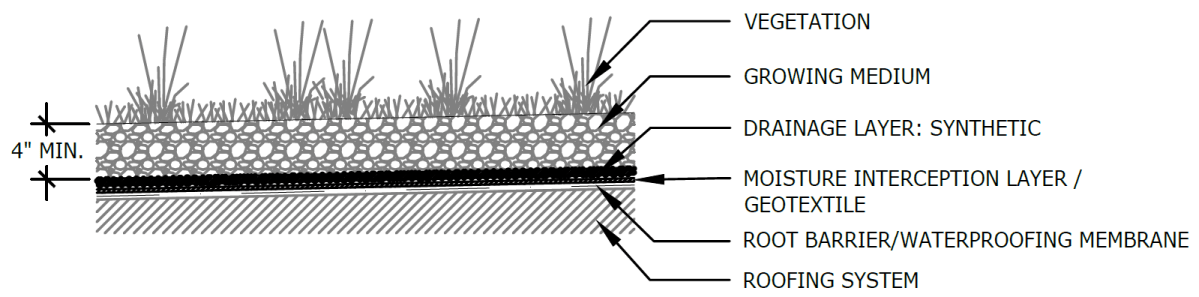
Figure 4.3‑4: Green roof (dual media) standard detail
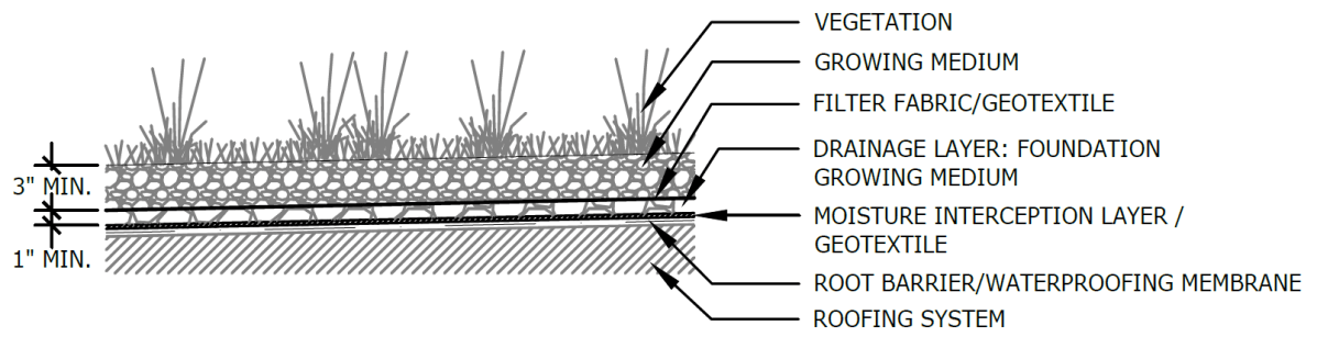
Figure 4.3‑5: Partially paved green roof with typical features standard detail
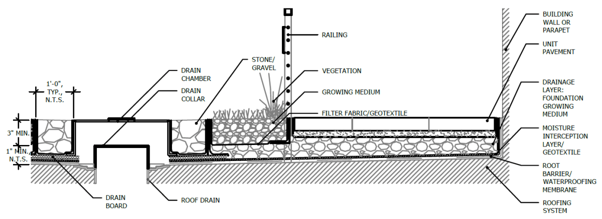
(The designer is referred to Appendix L to download Standard Detail CAD files.)
4.3.4 Green roof material standards
Inlet control material standards
- The designer is referred to Section 4.11, Inlet Controls, for information on material standards for inlet control systems.
Storage area material standards
- Green roof growing medium must be a lightweight mineral material with added organic material that meets the following specifications:
- Moisture content at maximum water holding capacity (ASTM E2399 or FLL): 40% to 60% (vol)
- Porosity at maximum water holding capacity (ASTM E2399 or FLL): 10% to 15%
- Density at maximum water holding capacity (ASTM E2399 or FLL): ≤ 85 lbs/ft3
- Total organic matter (MSA): 6% to 10% (dry weight)
- pH (MSA): 6.5 to 7.8
- Soluble salts (DPTA saturated media extraction): ≤ 2 mmhos/cm
- Water permeability (ASTM E2399 or FLL): 0.25 in/min to 1.25 in/min
- Grain-size distribution consisting of ≤ 4.5% passing for clay (0.002 mm) and 5% to 15% passing for silt (0.05 mm)
- The nutrients must be initially incorporated in the formulation of a suitable mix for the support of the specified plant materials.
- The medium must withstand freeze/thaw cycles.
- Foundation growth media (lightweight drainage aggregate) must be composed of a blended medium that meets the following specifications:
- Density at maximum water capacity (ASTM E2399‑05): ≤ 65 lbs/ft3
- Maximum water holding capacity: 15% to 25%
- Water permeability (ASTM E2396‑05): ≥ 25 in/min
- Total organic matter by loss on ignition (ASTM F1647): ≤ 1%
- Porosity (ASTM C29): 20% to 65%
- Grain-size distribution (ASTM C136) consisting of the following gradations:
- Pct. Passing US#18 sieve (1.0 mm): ≤ 5%
- Pct. Passing ¼‑inch sieve: ≤ 30%
- Pct. Passing 3/8‑inch sieve (9.5 mm): ≥ 75%
- Pct. Passing ½‑inch sieve (12 mm): 100%
- Geotextile must consist of polypropylene fibers and meet the following specifications:
- Grab Tensile Strength (ASTM-D4632): 70 lbs to 120 lbs
- CBR Puncture Strength (ASTM-D6241): 120 lbs to 340 lbs
- Flow Rate (ASTM-D4491): 130 gal/min/ft2 to 200 gal/min/ft2
- UV Resistance after 500 hrs (ASTM-D4355): 70%
- Tear Resistance (ASTM-D4533): 30 lbs to 50 lbs
- Heat-set or heat-calendared fabrics are not permitted.
- Drainage layer
- For vegetated roof cover assemblies with thicknesses of less than five inches, synthetic drainage layers may be used in lieu of granular drainage layers.
- For vegetated cover assemblies with an overall thickness of five inches, or greater, the drainage layer must meet the following specifications:
- Abrasion resistance (ASTM-C131-96): ≤ 25% loss
- Soundness (ASTM-C88): ≤ 5% loss
- Porosity (ASTM-C29): ≥ 25%
- Percent of particles passing 1/2‑inch sieve (ASTM-C136): ≥ 75%
- The minimum thickness of the granular layer must be two inches. The granular layer may be installed in conjunction with a synthetic reservoir sheet.
- Root barrier/waterproofing membrane
- PVC, EPDM, and thermal polyolefin (TPO) are permitted and inherently root resistant.
- All waterproof membranes must meet appropriate ASTM specifications. PVC membranes must meet ASTM D4434 requirements, EPDM membranes must meet ASTM D4637 requirements, and TPO membranes must meet ASTM D6878 requirements.
- Waterproofing membrane must be fully waterproof with properly sealed seams, corners, and protrusions to prevent any intrusion of standing water above the membrane.
- Roofing membranes must meet all building code requirements and guidelines of the City of Philadelphia.
Vegetation material standards
- Invasive species are not permitted in green roof planting. All plants must be appropriate and compatible with soil, hydrologic, light, and other site conditions. The designer is referred to Appendix I, Plant Lists.
- Plant species must be biodiverse. Species diversity for green roofs is defined as follows:
- Sedum: Include at least two genera (i.e., both Sedum and Phedimus) and six different species or cultivars in planting plans.
- Native or adaptive grasses: Provide at least two genera and three different species, if grasses are included in the design
- Native or adaptive perennials: Provide at least three genera and four different species, if perennials are included in the design
- Plant establishment:
- Plant establishment may be achieved through plugs, mats, container plants, and / or seed.
- The inclusion of seed as a supplement to live plants is required. The designer is referred to Section 4.13.3, Landscape Design Considerations, for a list of species appropriate for overseeding on green roofs.
- Temporary erosion control measures must be provided appropriate to the planting method during the plant establishment period.
- Perennials, grasses, grass-like plants, and groundcover plants must be healthy, well-rooted specimens.
- Green roof plantings must be able to withstand heat, cold, and high winds. After establishment, the plants must be self-sustaining and tolerant of drought conditions, with little to no need for fertilizers or pesticides.
- The only sedum known to be invasive, and which must be avoided is Sedum sarmentosum, also known as star sedum, gold moss, stringy stonecrop, or graveyard moss.
Outlet control material standards
- The designer is referred to Section 4.12, Outlet Controls, for information on material standards for outlet control systems.
Inspection and maintenance access material standards
- Personal protection systems must comply with OSHA Fall Protection Safety Standards and the ANSI and ASSE consensus-based fall protection standards.
4.3.5 Green roof construction guidance
- Inspect waterproof membrane for any irregularities that will interfere with drainage or may cause leaks. Do not continue until roofer has addressed defects.
- Install root barrier layer, if required.
- Install moisture-management layer or geotextile, as appropriate to the design.
- Install drainage layer.
- Install filter fabric, as appropriate to the design.
- Install growing medium, as specified.
- Install irrigation system with the growing medium, if included in design.
- Test the irrigation system, if included in design.
- Finish installing and grading growing medium
- Install wind protection, if included in the design. A wind scour blanket or hydromulch may be required to prevent erosion during the establishment period. It generally takes about two growing seasons for full establishment. High wind environments may necessitate permanent wind blankets.
- Establish vegetation.
- Green roofs can be effectively established by broadcasting fresh sedum cuttings during the spring and fall months. Depending on seasonal conditions, irrigation may be required after planting.
- Many perennial plants can be installed as plugs or container plants between April and November. Depending on the time of planting, temporary irrigation may be required.
- Perennials can be established from seed, except during the months of June, July, and August.
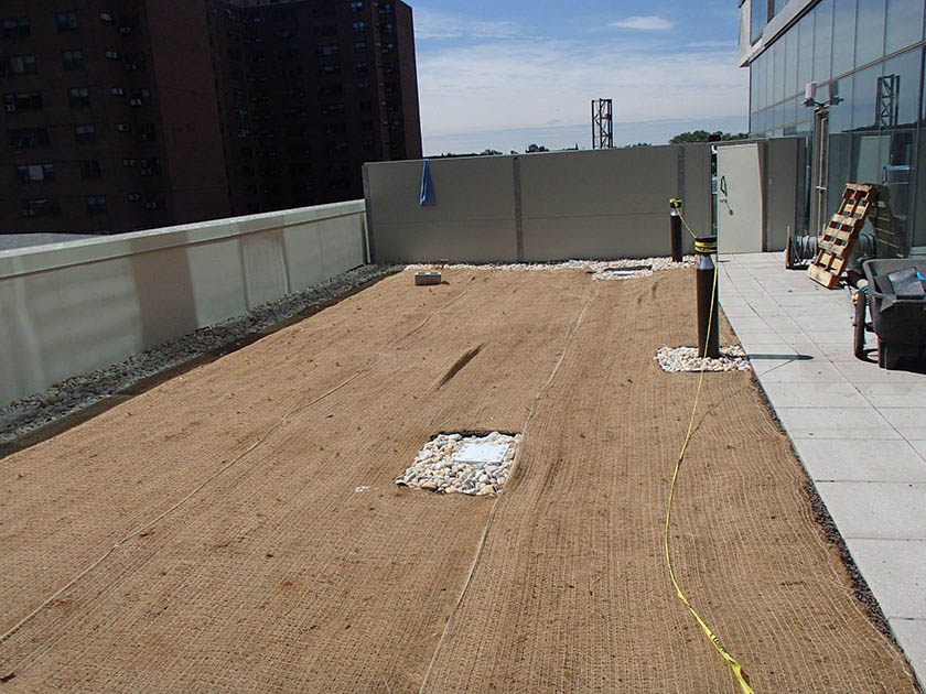
An example of a green roof installation in Philadelphia 4.3.6 Green roof maintenance guidance
Green roof maintenance activities largely focus on maintaining drainage capacity and the health of vegetation. Inspect all facility components, including vegetation, growing medium, filter fabric, drainage layer, and visible portions of the waterproof membrane to maximize the lifespan of the green roof.
Regardless of plant density and coverage, control of weed species is encouraged as part of long-term maintenance. The designer is referred to the Landscape Design Guidebook for more detail.
General recommended maintenance activities for green roofs are summarized in Table 4.3‑1 below.
Table 4.3‑1: Green roof maintenance guidelines
Early maintenance activity Frequency Water vegetation in the early morning. Daily for two weeks after installation Every four days for the first year after planting, during periods of four or more days without rain during June through August Hand-weed non-target / invasive plants. Every three months for the first two years after planting Inspect vegetation for signs of disease or distress. Treat or replace as necessary. Every two weeks for the first year after planting Ongoing maintenance activity Frequency Clear roof drains when growing medium, vegetation, debris, or other material clogs the drain inlet. Under normal operating conditions, all roof discharge must be filtered and growing medium must not migrate toward the drains. Identify and correct sources of sediment and debris. As needed Maintain plant material to provide a minimum of 80% foliage cover during warm months. If coverage rate is declining, determine the reason (e.g. soil nutrition, soil moisture conditions) and implement remedial measures. As needed Remove weeds manually and use herbicide only in extreme instances of weed infestations that compromise the plant cover integrity and when herbicides are permitted on a project site (e.g., certain sustainability rating systems do not allow chemical herbicides on site). Remove weeds entirely. As needed Thin any overgrown areas of vegetation Monthly Remove debris and sediment from impervious areas adjacent to green roof vegetation. Monthly Inspect root development. If root zone is not well developed, determine the reason (e.g., soil nutrition or soil moisture conditions) and implement remedial measures. Quarterly Inspect permanent irrigation system and adjust irrigation dosing rates as needed to optimize plant performance and water-use efficiency. Quarterly Inspect growing medium for evidence of erosion from wind or water. If erosion channels are evident, a problem with the drainage system or with the growing medium is present. Surface ponding or runoff must not occur except during very large rainfall events. Correct the problem then refresh the affected areas with additional growing medium and provide temporary soil stabilization. Consult with the Green Roof Manufacture for guidance on making repairs to green roof. Quarterly In early spring, manually cut dormant, herbaceous vegetation from the previous growing season to four to six inches above the ground. Annually Inspect drain inlet pipe and containment system. Annually Test growing medium for soluble nitrogen content. Fertilize as needed. Annually During the plant establishment period, conduct at least three to four maintenance visits per year to perform basic weeding, fertilization, and in-fill planting. Thereafter, conduct at least two annual visits for inspection and light weeding. Irrigated assemblies will require more frequent maintenance.
Use of herbicides must be minimized to prevent root penetration of waterproofing.
Apply organic or chemical fertilizer according to soil-testing results to maintain soluble nitrogen (nitrate and ammonium ion) levels between one and four ppm. The best source of nutrients for fertilization is mature compost.
Exercise spill-prevention measures from mechanical systems located on roofs when handling substances that can contaminate stormwater.
The designer is referred to Section 4.12, Outlet Controls, and Section 4.13, Landscaping, for information on maintenance guidance.
-
4.4 Subsurface Infiltration
Download summaries of this SMP and its maintenance guidance, with quick reference information for clients and developers:
4.4.1 Subsurface infiltration introduction
Subsurface infiltration stormwater management practices (SMPs) are typically stone beds, or basins, with storage pipes beneath landscaped or paved surfaces. Stormwater flows into the subsurface infiltration SMP where it collects within the aggregate void space and infiltrates into the surrounding soil. Dry wells, infiltration trenches, and infiltration beds are a few examples of this SMP type.
Subsurface infiltration SMPs can be combined with other SMPs in series to meet the Philadelphia Water Department (PWD) Stormwater Regulations (Stormwater Regulations). The designer is referred to Section 3.2.3 for information on using SMPs in series.
Design of subsurface infiltration SMPs is not limited to the examples shown within this text. Successful stormwater management plans will combine appropriate materials and designs specific to each site.
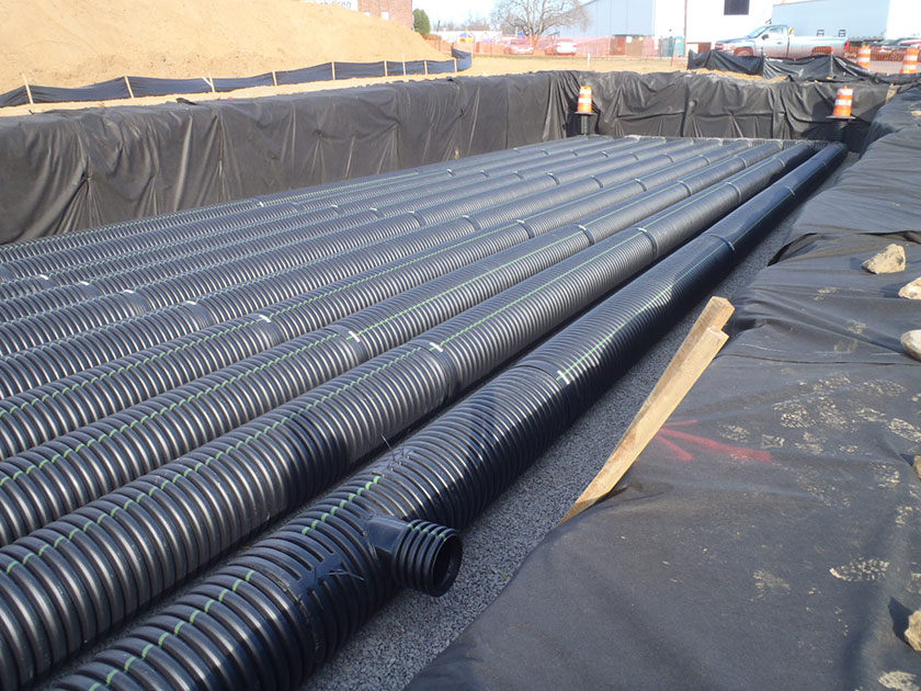
An example of a subsurface infiltration basin in Philadelphia When can subsurface infiltration be used?
Subsurface infiltration SMPs should be considered only if surface bioinfiltration/bioretention SMPs are not feasible on-site.
Subsurface infiltration SMPs must have underlying soils that, when tested pursuant to the infiltration testing procedure described in Section 3.3, are determined to be infiltration-feasible. They can be used to manage stormwater on both small and large sites. For large sites, multiple subsurface infiltration SMPs can be integrated throughout to manage larger areas.
Subsurface infiltration SMPs are versatile SMPs suitable for many types of development, from multi-family residential to high-density commercial projects. Provided that overburden loads and utility conflicts are evaluated, they can be sited beneath lawns and recreational areas, as well as parking lots and other hardscape surfaces.
Key advantages of subsurface infiltration
- Manages stormwater runoff without occupying surface or rooftop space
- Can be sited, through flexible design options, beneath lawns and recreational areas, as well as parking lots and other impervious areas when space constraints exist
- Can be a good option to meet the Flood Control requirement for constrained sites
Key limitations of subsurface infiltration
- Can be more costly and difficult to install and maintain than surface practices like bioinfiltration SMPs
- Not appropriate for runoff with high sediment loads without aggressive pretreatment
- Require strict adherence to regularly scheduled inspections because the maintenance needs are not easily visible
- Typically results in additional maintenance costs due to access limitations and Occupational Safety and Health Administration (OSHA) requirements
- Does not improve natural aesthetics or provide the ancillary environmental benefits associated with vegetated SMPs, such as habitat creation and improved air quality
Key design considerations for subsurface infiltration
- Appropriate pretreatment should be provided to remove sediment and debris before discharging to a subsurface infiltration system. A pretreatment approach should be developed based on the expected level of sediment loading and difficulty of sediment removal.
- Subsurface chambers, crates, pipes, or arches can be used to increase void space and reduce SMP footprint; however, proper analysis must be completed to ensure that loading ratio requirements are not exceeded.
- Long-term maintenance must also be carefully considered when evaluating such systems.
- The system and maintenance access should be located in an area where maintenance and potential repairs can be conducted with minimal disturbance to surrounding uses
- Structural suitability for overburden support and traffic loading should be considered, where applicable.
- Areas of soil contamination or unstable soils may need to be remediated or stabilized prior to subsurface infiltration SMP installation
- For any subsurface infiltration SMP that discharges onto an adjacent property, a drainage easement may be required and is recommended.
Subsurface infiltration types
Subsurface infiltration SMPs come in a variety of shapes and sizes, but commonly fit into the following three categories:
Underground stone storage consists of buried stone beds wrapped in geotextile that promote infiltration into subsoils. Stone storage beds provide the least amount of storage volume per unit area among the subsurface infiltration types. Removing sediment from underground stone storage is difficult, which necessitates effective pretreatment.
Underground pipe and chamber storage comprises perforated plastic or metal pipes, or pipe-like linear chambers, that are placed in a stone bed to provide more storage per unit volume and promote infiltration into subsoils. Various pipe dimensions and shapes can be used to optimize the storage volume to meet the specific site requirements. The designer is referred to Section 4.15 for information on drainage wells, a subsurface infiltration system that falls into this category.
Underground plastic grid storage consists of buried plastic structures that can be stacked and interconnected to form various shapes and sizes. Grid systems can provide as much as 95% void space for storage of stormwater.
4.4.2 Subsurface infiltration components
Figure 4.4‑1: Subsurface infiltration with typical features
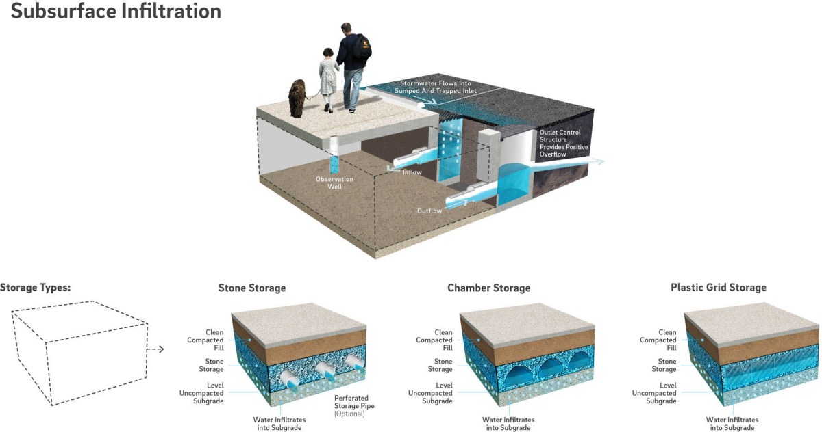
Pretreatment component
Pretreatment systems capture trash, sediment, and/or pollutants from stormwater runoff before delivery to the infiltration area. Pretreatment needs will vary significantly depending on the contributing drainage area composition and use. Pretreatment can include structures such as sumped and trapped inlets, sediment/grit chambers or separators, media filters, inlet inserts, or other appropriate prefabricated or proprietary designs to remove sediment, floatables, and/or hydrocarbons from stormwater runoff prior to being conveyed to a subsurface infiltration SMP. While inlet hoods are preferred, permanent filter bags may be accepted for Stormwater Retrofit projects where existing inlets do not have hoods and inlet reconstruction is not feasible. In addition to sumped and trapped inlets, permanent filter bag inserts are required for sites that generate pollutants such as loading docks, material storage facilities, junk yards, and waste collection and disposal sites. Permanent filter bags will require frequent cleanings.
Pretreatment can also consist of maintenance rows, filter strips, forebays, and swales. The designer is referred to Section 4.10, Pretreatment, for more information on pretreatment systems.
Inlet control component
Inlet control systems convey and control the flow of stormwater from the contributing catchment area to a subsurface infiltration SMP. Inlet control needs will vary depending on the design of stormwater conveyance systems and the site layout. The designer is referred to Section 3.4.2 for guidance on stormwater conveyance system design.
Inlet controls may include flow splitters, curbless design/curb openings, energy dissipaters, and inlets. The designer is referred to Section 4.11, Inlet Controls, for more information on inlet controls.
Storage area component
Storage areas within subsurface infiltration SMPs temporarily hold stormwater runoff as it infiltrates into native soils. The storage component of a subsurface infiltration SMP is typically constructed of a stone-filled, level-bottomed bed or trench, which may or may not incorporate pipes, arches, concrete vaults, crates, plastic grids, or other proprietary structures. The void spaces between the stones and/or structures store stormwater until it can infiltrate into the surrounding soils.
Outlet control component
Outlet controls within a subsurface infiltration SMP can provide a range of functions, including the following:
- Controlling how much water is stored for infiltration;
- Meeting drain down time requirements;
- Controlling the rate of discharge from the SMP and limiting water surface elevations during various storm events; and/or
- Bypassing of flows from large storm events.
Outlet controls may include orifices, weirs, or level spreaders. The designer is referred to Section 4.12, Outlet Controls, for more information on outlet controls.
Inspection and maintenance access component
Safe and easy inspection and maintenance access to all major components within a subsurface infiltration SMP is critical to ensuring long-term performance. Access points provide access to subsurface systems, both for inspections and routine maintenance, and for pumping water out of subsurface SMPs in cases of failure or severe damage. Manholes provide access for maintenance personnel and equipment to perform maintenance and inspections. Cleanouts provide access for hoses and vacuum equipment. Observation wells provide access to the bottom of subsurface systems for performance inspections and monitoring. Access structures may also serve additional functions, such as joining subsurface pipes.
4.4.3 Subsurface infiltration design standards
General design standards
- The maximum allowable drain down time is 72 hours after the 24‑hour storm event.
- The maximum allowable directly connected impervious area (DCIA) to SMP footprint loading ratio is 10:1.
- Positive overflow must be provided for large storm events, up to and including the 100‑year, 24‑hour storm, or, if the project is exempt from Flood Control, the ten‑year, 24‑hour storm. Overflow structures and pipes must be designed to convey at least the ten‑year, 24‑hour storm.
- The minimum allowable distance between subsurface infiltration basins and any adjacent private property line is ten feet. This includes partially lined basins. It is acceptable for SMPs to be located directly adjacent to the public right-of-way (ROW).
- The minimum allowable distance between subsurface infiltration basins and any building or retaining wall is ten feet. This includes partially lined basins. The following requirements and exceptions apply:
- For existing and proposed buildings with basements, the setback is measured from the basement wall.
- For existing buildings without basements and existing retaining walls, the setback is measured from the foundation and may be waived if a signed and sealed geotechnical analysis is submitted that evaluates the impacts of infiltration and excavation on the existing foundation and determines it to be feasible.
- For proposed buildings without basements and proposed retaining walls, the setback is measured from the foundation and may be waived if the foundation is proposed to be designed with the basin’s proximity in mind.
- Infiltration requirements:
- The designer is referred to Section 3.3 for information on infiltration testing requirements.
- The SMP must be located at least two feet above any poorly infiltrating soils, seasonal high groundwater table, bedrock, or any other limiting zone.
- For hydrologic modeling, infiltration must be applied to the horizontal surface area (SMP footprint), not the wetted area.
- Soils underlying infiltration practices must, when tested pursuant to the infiltration testing procedure described in Section 3.3, be determined to be infiltration feasible. If infiltration feasibility is unknown and determination is deferred until construction, the applicant must submit two complete designs (e.g. plans, calculations, Online Technical Worksheet, etc.) for both infiltrating and non-infiltrating scenarios to be fully reviewed. A PCSMP Conditional Approval will be issued, and the approval letter will feature both plan sets. Following infiltration testing, only the applicable design’s plan set will be included on the PCSMP Approval Letter.
- Soils with rates in excess of ten inches per hour require soil amendments. During construction, upon achieving final subgrade elevations, a two‑foot-thick layer of amended soil must be placed across the entire cross-section of the infiltrating SMP, below the bottom elevation of the SMP, and a minimum of three infiltration tests must be performed within the amended soil layer. If soil amendments are installed and the tested infiltration rate is determined to be outside of the PWD-allowable range or varies significantly from the design infiltration rate, additional soil amendments and/or a SMP redesign will be required. The designer is referred to Section 3.3 for additional detail.
- If the infiltration SMP is used as a temporary sediment basin during construction, the invert elevation of the infiltration SMP must be a minimum of three feet below the bottom elevation of the pre-basin-conversion sediment basin.
- An infiltrating SMP within the zone of influence of any nearby sewers or sewer laterals must be installed with an impervious liner. The zone of influence is defined by the area within a 1:1 (H:V) slope line from the outer edge of a sewer or sewer lateral.
- Structural suitability for overburden support and traffic loading must be considered, where applicable.
Pretreatment design standards
- Acceptable form(s) of pretreatment must be incorporated into design. Pretreatment of runoff from all inlets is required. At a minimum, this can be achieved through the use of sumps and traps for inlets, sump boxes with traps downstream of trench drains, and filter strips for overland flow.
- The designer is referred to Section 4.10, Pretreatment, for more information on design standards for pretreatment systems.
Inlet control design standards
- The designer is referred to Section 4.11, Inlet Controls, for information on design standards for inlet control systems.
Storage area design standards
- The storage area must provide static storage for the Water Quality Volume (WQv) between the bottom elevation of the SMP and the elevation of the lowest outlet, including storage voids. Storage or distribution pipes alone are not sufficient in providing static storage. A minimum of at least three inches of forced storage via an outlet control device is recommended in order to give the statically stored volume time to infiltrate.
- The maximum allowable static storage volume without supporting documentation (defined below) is the runoff volume from the one‑year, 24‑hour storm.
- The maximum allowable static storage volume with supporting documentation is the runoff volume from the ten‑year, 24‑hour storm. Requirements for supporting documentation include a letter, signed and sealed by both the geotechnical and design engineer, indicating that the proposed design is recommended, with the following components acknowledged and considered. The designer is encouraged to contact PWD for further guidance when pursuing this design.
- A summary of the long-term impacts to the neighboring properties, including, but not limited to subsidence, change in basement moisture/ water, and structural damage;
- The location of the groundwater table;
- References to other projects that have successfully infiltrated more than the one‑year, 24‑hour storm event; and
- Rigorous pretreatment to promote longevity of the infiltration SMP.
- When SMPs are used in series, the storage areas for all SMPs must provide cumulative static storage for the WQv, but there is no minimum storage requirement for each individual SMP used in series.
- Subsurface infiltration SMPs can be designed with additional storage beyond the WQv and with outlet controls that allow all remaining applicable Stormwater Regulations to be met.
- Void space provided by linear chamber systems, plastic grids, or other related structures must be as specified by the manufacturer and noted in supporting documentation.
- Bedding and foundations:
- Pipe, vault, grid, and chamber storage areas must be adequately bedded with stone to prevent settling or subsidence.
- Bedding thickness must vary according to system requirements but must not be less than six inches.
- Over-excavation and replacement of loose or unstable subsurface material may be required if such conditions are encountered. A geotechnical engineer or other appropriate design professional should be consulted for additional guidance.
- Foundations/footers must be provided as warranted by system loading, geotechnical conditions, and manufacturer’s recommendations. Foundation designs must be performed by an appropriate design professional.
- The storage design must account for potential loading from vehicles, as appropriate, based on expected maximum active loading, including consideration for emergency vehicles.
- Porosity values for storage volume calculations are as follows:
- Soil media: 0.20
- Sand: 0.30
- Stone: 0.40
- Stone must be separated from soil media by a geotextile or a pea gravel filter to prevent sand, silt, and sediment from entering the system.
- Stone storage systems must have a level bottom or use a terraced system if installed along a slope.
Outlet control design standards
- The designer is referred to Section 4.12, Outlet Controls, for information on design standards for outlet control systems.
Inspection and maintenance access design standards
- Cleanouts, manholes, access panels and other access features must be provided to allow unobstructed and safe access to SMPs for routine maintenance and inspection of inflow, outflow, underdrains, and storage systems.
- Observation wells must be provided for SMPs that include stone storage and must meet the following requirements:
- The observation well must be placed at the invert of the stone bed.
- The observation well must be located near the center of the stone bed system to monitor the level and duration of water stored within the SMP (drain down time). A minimum of six inches of clearance must be provided between the edge of the observation well’s concrete ring or frame and any nearby site features (curbing, tree pits, sidewalk edge, etc.). Plan view dimensioning for the proposed location of the observation well, relative to the boundaries of the SMP it lies within, must be provided on the plans.
- Adequate inspection and maintenance access to the observation well must be provided.
- An observation well located in a paved area must be outfitted with a cover and frame. The cover plate must be installed flush with the surrounding surface at finished grade, and grading should drain away from the observation well wherever possible. The solid section of the observation well must extend into the cover frame enough such that a bentonite/cement seal can be placed around the well within the frame, and a solid slip-on cap can be fitted onto the pipe end.
- An observation well located in an unpaved area must have a concrete ring or frame poured for support, with three lengths of rebar evenly spaced around the ring and three inches from its outer edge. The observation well should be located outside of the ponding area of any surface SMPs. If, due to space limitations, an observation well must be placed in the ponding area of a surface SMP, the concrete ring and well cover must extend three inches above the SMP’s maximum ponding depth.
- The observation well must include a slotted section within the storage layer of the SMP. The top of the slotted well section must extend to a minimum of six inches below the top of the SMP storage layer, and the slotted section must extend down the entire depth of the SMP.
- Access features for subsurface infiltration SMPs:
- Access features must be provided for all underground storage SMPs that are not stone storage beds.
- A sufficient number of access points in the SMP must be provided to efficiently inspect and maintain the infiltration area.
- For cast-in-place vault systems, access features must consist of manholes or grated access panels or doors. Grated access panels are preferred to maintain airflow.
- For grid storage or other manufactured systems, the manufacturer’s recommendations must be followed.
- Ladder access is required for vaults greater than four feet in height.
- Header pipes, at minimum 36‑inch diameter, connected to manholes at each corner of the subsurface infiltration SMP must be provided. Alternatively, smaller header pipes may be used if cleanouts are provided on the manifold/header pipe junction for each distribution pipe. The cleanouts must be on alternating sides of the SMP.
Figure 4.4‑2: Subsurface infiltration basin (pipe in stone) standard detail
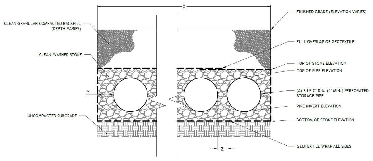
(The designer is referred to Appendix L to download Standard Detail CAD files.)
4.4.4 Subsurface infiltration material standards
Pretreatment material standards
- The designer is referred to Section 4.10, Pretreatment, for information on materials standards for pretreatment systems.
Inlet control material standards
- The designer is referred to Section 4.11, Inlet Controls, for information on material standards for inlet control systems.
Storage area material standards
- Stone designed for stormwater storage must be uniformly graded, crushed, clean-washed stone. PWD defines “clean-washed” as having less than 0.5% wash loss, by mass, when tested per American Association of State Highway and Transportation Officials (AASHTO) T-11 wash loss test. AASHTO No. 3 and No. 57 stone can meet this specification.
- Sand, if used, must be AASHTO M‑6 or ASTM C‑33 sand and must have a grain size of 0.02 inches to 0.04 inches.
- Storage pipes:
- Pipe used within the subsurface infiltration SMP must be continuously perforated and have a smooth interior with a minimum inner diameter of four inches.
- High-density polyethylene (HDPE) pipe must meet the specifications of AASHTO M252, Type S or AASHTO M294, Type S.
- Any pipe materials outside the SMP are to meet City Plumbing Code Standards.
- Geotextile must consist of polypropylene fibers and meet the following specifications (AASHTO Class 1 or Class 2 geotextile is recommended):
- Grab Tensile Strength (ASTM-D4632): ≥ 205 lbs
- CBR Puncture Strength (ASTM-D6241): ≥ 500 lbs
- Flow Rate (ASTM-D4491): ≥ 95 gal/min/ft2
- UV Resistance after 500 hours (ASTM-D4355): ≥ 70%
- Tear Resistance (ASTM-D4533): ≥ 80 lbs
- Heat-set or heat-calendared fabrics are not permitted.
Outlet control material standards
- The designer is referred to Section 4.12, Outlet Controls, for information on material standards for outlet control systems.
Inspection and maintenance access material standards
- Observation wells:
- The observation well must consist of slotted plastic pipe with a minimum inner diameter of four inches and a solid cap at the surface. The slotted section of the well must consist of PVC slotted well screen with 0.01‑inch slot size and an attached perforated PVC cap at the bottom.
- The observation well’s cover must be ductile iron in a gray iron frame.
- For an observation well located in an unpaved area, the well’s concrete ring must be a minimum of six inches wider in any dimension than the cover frame, of equal depth as the cover frame itself, and poured atop a minimum of six inches of AASHTO #57 stone bedding. A frame conforming to these minimum dimensions may be circular or square.
- Cleanouts must be made of material with a smooth interior having a minimum inner diameter of six inches. If the connecting pipe is eight inches in diameter or larger, then the cleanout must be eight inches in diameter.
4.4.5 Subsurface infiltration construction guidance
Proper construction and careful consideration of soil compaction, infiltration performance, and sedimentation control of subsurface infiltration SMPs are essential to ensure long-term functionality and reduce long-term maintenance needs and costs. Since subsurface infiltration SMPs are, by definition, buried, construction oversight is critical. At a minimum, verification of volumes, grades, and elevations must be performed prior to backfill.
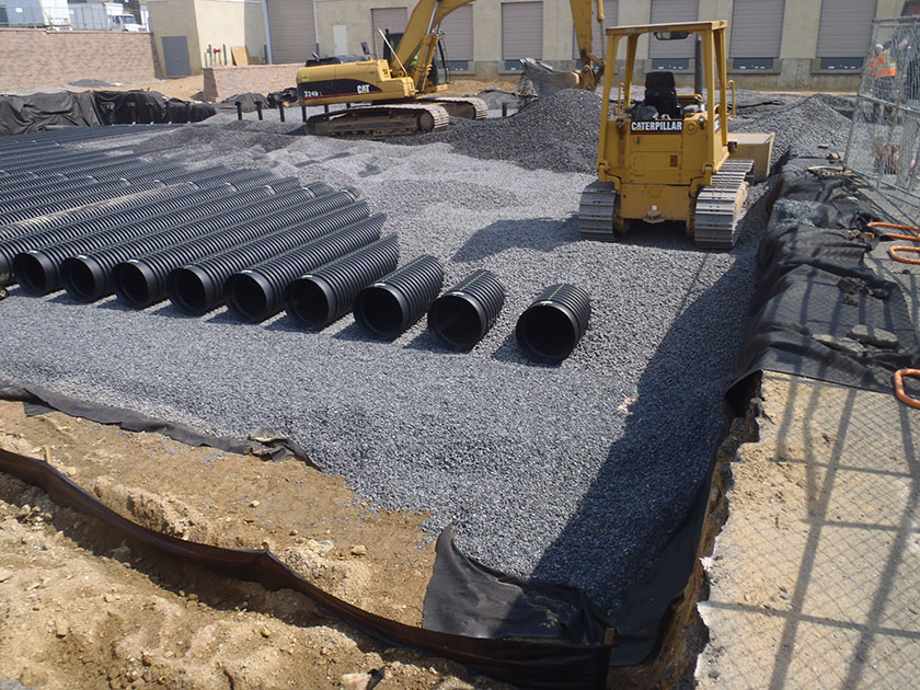
An example of a subsurface infiltration basin installation in Philadelphia - Areas for proposed subsurface infiltration SMPs must be physically marked as heavy equipment exclusion zones prior to any land-disturbing activities to avoid soil disturbance and compaction during construction. Install construction fencing around subsurface infiltration areas. If areas are compacted during construction, additional infiltration testing and potential redesign efforts may be required.
- Provide erosion and sedimentation control protection on the site such that construction runoff is directed away from the proposed subsurface infiltration SMP. Sediment deposited in a subsurface infiltration SMP during construction, particularly a stone bed, can significantly reduce SMP performance. The designer is referred to the latest edition of the Pennsylvania Department of Environmental Protection (PA DEP) Erosion and Sediment Pollution Control Program Manual for information on design standards for erosion and sedimentation control practices.
- Infiltration areas may not be used as sediment traps during construction, unless at least three feet of soil are left in place while the area is serving as a sediment trap and subsequently removed during construction after the contributing drainage areas have been stabilized.
- Complete site elevation grading and stabilize all disturbed soil. Stabilization of disturbed areas must be implemented before finalizing the subsurface infiltration SMP’s excavation and construction.
- Excavate subsurface infiltration area to proposed depth and manually grade and scarify the existing soil surface. The bottom of the infiltration bed must be at a level grade.
- Existing subgrade must NOT be compacted or subject to excessive construction equipment prior to placement of geotextile and stone bed. The use of machinery to load stone from outside of the infiltration bed footprint is recommended. Stone should be carefully placed, not dumped, in the infiltration bed. If it is essential that equipment be used in the excavated area, all equipment must be low ground pressure equipment and approved by PWD. Use of equipment with narrow tracks or tires, rubber tires with large lugs, or high-pressure tires will cause excessive compaction and must not be used. Should the subgrade be compacted during construction, additional testing of soil infiltration rates and SMP redesign may be required. Rock construction entrances must not be located on top of areas proposed for infiltration practices.
- Place geotextile and stone aggregate immediately after approval of subgrade preparation to prevent accumulation of debris or sediment. Prevent runoff and sediment from entering the infiltration bed during the placement of the geotextile and aggregate bed.
- Place geotextile in accordance with manufacturer’s standards and recommendations. Secure geotextile at least four feet outside of bed. Adjacent strips of filter fabric must overlap a minimum of 16 inches
- Install aggregate course in lifts of six to eight inches. Lightly compact each layer with equipment, keeping equipment movement over storage bed subgrades to a minimum. Install aggregate to grades indicated on the drawings.
- All stone that makes up the infiltration SMP must remain free of sediment. If sediment enters the stone, the contractor may be required to remove the sediment and replace with clean washed stone.
- Confirm and document invert elevations and dimensions for all structures such as chambers and pipes prior to backfill.
- Backfill to finished grade. Ensure backfill is properly compacted in accordance with specifications. Ensure backfill process does not disrupt pipe placement and configuration.
- Structures such as inlet boxes, reinforced concrete boxes, inlet controls, and outlet controls must be constructed according to manufacturer’s guidelines or design professional’s guidance.
- Complete surface grading above subsurface infiltration SMP, using suitable equipment to avoid excess compaction.
- Once the site is permanently stabilized with vegetation, remove temporary erosion and sediment control measures.
4.4.6 Subsurface infiltration maintenance guidance
Maintenance of subsurface infiltration SMPs focuses on the periodic removal of sediment and debris from pretreatment and storage areas. Sediment removal from vaults, chambers, and pipes is typically conducted using vacuum or flushing systems. Guidance on the use and operation of vacuum or flushing sediment removal equipment is beyond the scope of this Manual; a maintenance professional should be contacted for additional details. As applicable, subsurface SMP maintenance procedures must meet OSHA confined space entry requirements.
General recommended maintenance activities for subsurface infiltration SMPs are summarized in Table 4.4‑1.
Table 4.4‑1: Subsurface infiltration maintenance guidelines
Early maintenance activity Frequency Inspect erosion control and flow spreading devices until soil settlement and vegetative establishment of contributing areas has occurred. Biweekly Inspect inlet controls, outlet structures, and storage areas for trash and sediment accumulation. Monthly for the first year after installation to determine ongoing maintenance frequency Ongoing maintenance activity Frequency Regularly clean out gutters and catch basins to reduce sediment load to infiltration SMP. Clean intermediate sump boxes, replace filters, and otherwise clean pretreatment areas in directly connected systems. As needed Remove sediment and debris from subsurface infiltration SMP sedimentation chamber, as applicable, when the sediment zone is 3/4 full. Sediment and debris build‑up may need to be removed by a professional. Consult with a professional as necessary. As needed Remove sediment and debris from pipe/vault systems. Sediment depth is not to reach a maximum depth of four inches below the SMP’s outlet invert elevation. Removal of sediment from grid systems must be per manufacturer’s recommendations or as per the site-specific maintenance plan. As needed Replace filter bags for pretreatment devices. Ensure filter bag is installed properly. Quarterly Inspect subsurface infiltration facility and control structures. Quarterly Remove floating debris and accumulated petroleum products from system and all components. Quarterly Evaluate the drain down time of the SMP after a storm of at least one inch to ensure a SMP drain down time of less than 72 hours. Ongoing Maintain records of all inspections and maintenance activity. Ongoing The designer is referred to Section 4.10, Pretreatment, Section 4.11, Inlet Controls, and Section 4.12, Outlet Controls, for information on maintenance guidance for pretreatment, inlet controls, and outlet controls.
-
4.5 Cisterns
Download summaries of this SMP and its maintenance guidance, with quick reference information for clients and developers:
4.5.1 Cistern introduction
Cisterns are storage tanks, located either above or below ground, that hold rainwater for beneficial reuse. Cisterns are multi-function systems that help to meet the Philadelphia Water Department (PWD) Stormwater Regulations (Stormwater Regulations) and collect water for reuse. Rainwater may be collected from rooftops or other impervious surfaces and conveyed to cisterns for storage. Stored water may drain by gravity or be pumped to its ultimate end use. This process, often referred to as rainwater harvesting, may include the use of captured water as permitted by local plumbing and building codes for:
- Exterior washing (e.g., car washes, building facades, sidewalks);
- Make-up water for mechanical systems (e.g., cooling towers, condensate make-up);
- Ornamental water fountains;
- Toilet and urinal flushing;
- Laundry; and/or
- Other uses, as approved.
Irrigation as a use for runoff stored in a cistern is not an acceptable strategy for meeting the Stormwater Regulations.
Sizing considerations for cisterns include both the frequency and volume of water usage demand, if applicable, and the frequency and volume of supply. Cisterns may also be sized to provide detention/flow control along with water conservation as a hybrid system.
Cisterns only provide an effective flow control function if the stored water is partially or fully used (or emptied) between storms. This function restores available storage volume within the cistern in advance of the next storm. For example, unless it is oversized, a fire storage system provides no meaningful stormwater benefit if it is fed by rainwater because fire storage systems must always be full, in case there is a fire.
Cisterns can be combined with other stormwater management practices (SMPs) in series to meet the Stormwater Regulations. The designer is referred to Section 3.2.3 for information on using SMPs in series.
The design recommendations within this section are to serve as guidance only. Site-specific parameters, such as anticipated water demand, will dictate alternative designs and calculations which will be reviewed accordingly.

An example of a surface cistern in Philadelphia 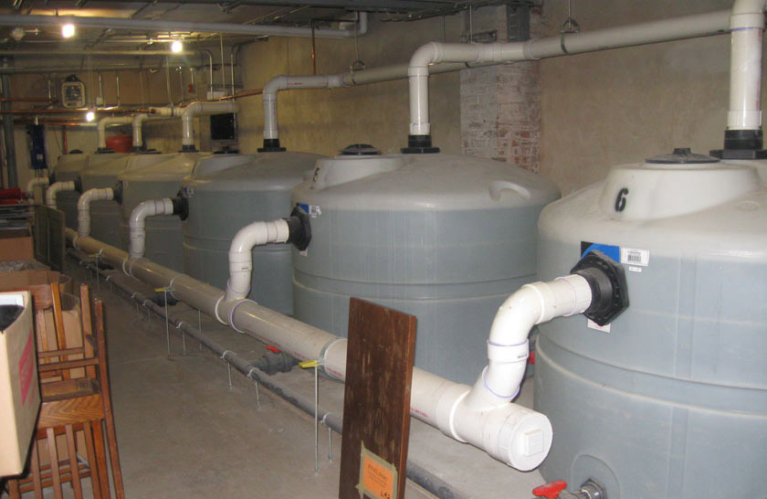
An example of a subsurface cistern in Philadelphia When can cisterns be used?
Cisterns can be used as part of a comprehensive stormwater compliance and reuse strategy for residential, commercial, and industrial areas. They are typically located within or adjacent to buildings. In addition to above-ground cisterns, rainwater harvesting systems can be sited beneath lawns, recreational areas, parking lots, and other hardscape surfaces, provided that overburden loads and utility conflicts are evaluated.
Key advantages of cisterns
- Can be used to provide rate control within small/constrained spaces
- Decrease demand on the municipal water supply and water costs for the end user, when used as part of a rainwater harvesting system in accordance with City, State, and Federal code restrictions
- Can be sited, through flexible design options, beneath lawns, recreational areas, parking lots, other impervious areas, or within buildings when space constraints exist
- Provide educational benefits, especially at public and/or highly visible sites
Key limitations of cisterns
- May not be able to fully meet the Water Quality requirement
- Limited to circumstances where there is a year-round water demand that can replenish storage capacity between storms
- May be subject to additional City, State, and Federal code restrictions
- Require draining before a freeze when located on the surface, to prevent structural damage
- Require strict adherence to regularly scheduled inspections because the maintenance needs are not easily visible
- Does not improve aesthetics or provide the ancillary environmental benefits associated with vegetated SMPs, such as habitat creation and improved air quality
Key design considerations for cisterns
- The specific end use of harvested rainwater can influence other design considerations, including cistern location, type of treatment, and delivery and distribution, among others.
- If a cistern is used for rainwater harvesting, a distribution system is needed to deliver stored water to its ultimate end use. It is often best to locate a cistern close to the building or drainage area to limit the amount of pipe needed for delivery or distribution of water. Pumps can be used to convey stored rainwater to the end use. When the water is being routed from the cistern to the inside of a building for non-potable use, pumps can be used to feed a much smaller pressure tank inside the building, which then serves the internal water demands. Cisterns can also use gravity flow to accommodate indoor residential uses (e.g., laundry) that do not require high water pressure.
- Depending on the intended use for the captured water, the level of treatment can vary. For some non-potable uses, filtration can be limited to sediment removal. Other uses may require treatment to remove microorganisms via physical filtration and disinfection.
- Cisterns can be placed underground, indoors, adjacent to buildings, and on rooftops that are structurally designed to support the added weight. The designer can work with architects and landscape architects to strategically site the cisterns. If cisterns are sited near the ultimate end use, costly distribution systems can be minimized.
- Rainwater harvesting is most effective when the volume and frequency of rainfall and the size of the contributing drainage area can generate sufficient water for the ultimate end use. Rooftops are most often targeted for rainwater harvesting systems. Rainwater can also be harvested from other impervious surfaces, such as parking lots; however, this typically requires more extensive treatment prior to use. Water Quality compliance is largely a function of the type of material covering the drainage area.
- For any cistern that discharges onto an adjacent property, a drainage easement may be required and is recommended.
Cistern types
Cisterns can be distinguished by their location and by the type of water use they support. With respect to location, cisterns can be categorized in two ways.
Surface tank systems can be sited on rooftops or integrated into commercial sites. They may drain by gravity or be pumped.
Subsurface tank systems are typically pumped. Because the cisterns are below the surface, they do not interfere with the landscape.
With respect to use of stored water, rainwater harvesting systems can be categorized in three ways.
Runoff can be captured and stored for outdoor use, including exterior washing and architectural water features. Irrigation as a use for runoff stored in a cistern is not an acceptable strategy for meeting the Stormwater Regulations.
Runoff can be captured and stored for indoor use if properly treated and managed. A non-potable rainwater harvesting system cannot be directly connected to the potable plumbing of a building. The non-potable plumbing needs to be kept separate and properly labeled. With more extensive treatment, rainwater may be used for drinking purposes. The designer should seek professional guidance on the rules governing non-public potable water.
When a specific use for harvested rainwater cannot be identified or when the supply of harvested rainwater significantly exceeds demand, then a hybrid system using both water conservation and a delayed discharge to a down-gradient pervious area or another SMP can be considered.
4.5.2 Cistern components
Figure 4.5‑1: Surface cistern with typical features
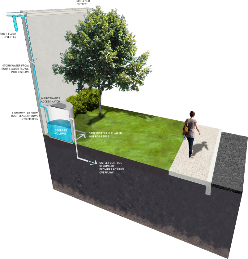
Pretreatment component
Pretreatment systems capture trash, sediment, and/or other pollutants from stormwater runoff before delivery to the storage area. Pretreatment needs will vary significantly depending on the contributing drainage area composition and use. Pretreatment can include structures such as sumped and trapped inlets, sediment/grit chambers, media filters, inlet inserts, or other appropriate prefabricated or proprietary designs to remove sediment, floatables, and/or hydrocarbons from stormwater runoff prior to being conveyed to a cistern. While inlet hoods are preferred, permanent filter bags may be accepted for Stormwater Retrofit projects where existing inlets do not have hoods and inlet reconstruction is not feasible. In addition to sumped and trapped inlets, permanent filter bag inserts are required for sites that generate pollutants such as loading docks, material storage facilities, junk yards, and waste collection and disposal sites. Permanent filter bags will require frequent cleanings.
The designer is referred to Section 4.10, Pretreatment, for more information.
The following pretreatment options are often used with cisterns that manage roof runoff:
Gutter screening – All larger debris (e.g., leaves and twigs) must be screened at the gutter, roof, or at the edge of the impervious surface.
Prefiltration devices – Prefiltration devices prevent smaller particles from entering the cistern. The choice of the proper type of prefiltration device depends on cistern configuration and rainfall patterns.
- First flush diverters route the first flow, or flush, of water from the catchment surface away from the cistern prior to entry into the tank. While gutter screens are effective at removing larger debris such as leaves and twigs, first flush diverters can be used to remove smaller contaminants such as dust, pollen, bacteria from insect and animal droppings, and other harmful contaminants. Options for first flush can include a standpipe with slow drainage and a floating ball that seals off the top of the diverter pipe, among others.
- Roof washers are placed just ahead of cisterns and are used to filter small debris from harvested rainwater. Roof washers use a small tank, usually between 25 and 50 gallons in size, with leaf strainers and a filter with openings as small as 30 microns. The filter functions to remove very small particulate matter from harvested rainwater. All roof washers must be cleaned on a regular basis.
- Rainwater pre-filters screen rainwater before it enters the cistern on a continuous flow basis. These screens are preferable to first flush diverters and roof washers because they have significantly higher collection efficiencies.
The designer is referred to Section 4.10, Pretreatment, for more information.
Inlet control component
Inlet control systems convey and control the flow of stormwater from the contributing catchment area to a cistern. Inlet control needs will vary depending on the design of stormwater conveyance systems and the site layout. The designer is referred to Section 3.4.2 for guidance on stormwater conveyance system design.
The designer is referred to Section 4.11, Inlet Controls, for more information.
Storage area component
The storage component is the cistern, or tank, itself, which temporarily holds stormwater runoff before it can either be reused or be released downstream at a controlled rate, depending on the system design. Cistern capacities generally range from 50 to 50,000 gallons, but they can be as large as 100,000 gallons or more for larger projects. Multiple cisterns can be connected in series to balance water levels and to tailor to the storage volume needed.
Outlet control component
Outlet controls within a cistern control the amount of water that is stored for reuse and the rate at which the excess water is discharged from the cistern. These structures can provide a range of functions, including the following:
- Controlling how much water is stored for reuse;
- Meeting drain down time requirements;
- Controlling the rate of discharge from the SMP and limiting water surface elevations during various storm events; and/or
- Bypassing of flows from large storm events.
Outlet controls may include orifices and weirs. The designer is referred to Section 4.12, Outlet Controls, for more information.
Inspection and maintenance access component
Safe and easy inspection and maintenance access to all major components within a cistern is critical to ensuring long-term performance. Inspection and maintenance access structures provide a portal to subsurface structures within a cistern. They most commonly consist of a panel, port, or manhole. Access points provide access to subsurface cisterns, both for inspections and routine maintenance, and for pumping water out of subsurface cisterns in cases of failure or severe damage. Manholes provide access for maintenance personnel and equipment to perform maintenance and inspections. Cleanouts provide access for hoses and vacuum equipment. Observation wells provide access to the bottom of subsurface cisterns for performance inspections and monitoring. Access structures may also serve additional functions, such as joining subsurface pipes. The design of water distribution systems, internal plumbing systems, and water treatment systems required for rainwater harvesting end uses is beyond the scope of this Manual.
Figure 4.5‑2: Subsurface cistern with typical features
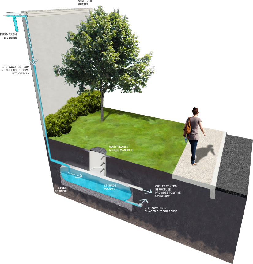
4.5.3 Cistern design standards
General design standards
- The maximum allowable drain down/withdrawal time for any portion of storage intended to meet the Water Quality requirement is 72 hours after the 24‑hour storm event.
- Positive overflow must be provided for large storm events, up to and including the 100‑year, 24‑hour storm, or, if the project is exempt from Flood Control, the ten‑year, 24‑hour storm. Overflow structures and pipes must be designed to convey at least the ten‑year, 24‑hour storm.
- The minimum allowable freeboard above maximum ponding depth is four inches or the diameter of the outlet pipe, whichever is greater.
- The soil bearing capacity or foundation upon which the cistern will be placed must be considered, as full cisterns can be very heavy. This is particularly important for above-ground cisterns, as significant settling could cause the cistern to lean or be damaged.
- Designers must consult the City’s Building and Plumbing Codes (administered by the City of Philadelphia Department of Licenses and Inspections (L&I)) to determine the allowable indoor uses and pipe labeling and routing (i.e., separate stud bays), and State and Federal codes for required treatment and management of harvested rainwater.
- In cases where a municipal backup supply is used, rainwater harvesting systems must have backflow preventers or air gaps to keep non-potable harvested water separate from the potable water supply. Distribution and waste pipes, internal to the building, must be designated as such per the City’s Building and Plumbing Codes (administered by L&I).
Pretreatment design standards
- Pretreatment of runoff from all inlets is required to keep sediment, leaves, contaminants, and other debris from the system. The purpose of pretreatment is to maintain functionality and cleanliness of pumps and to significantly cut down on maintenance by preventing organic buildup in the cistern, thereby decreasing microbial food sources.
- Acceptable form(s) of pretreatment include, at a minimum, sumps and traps for inlets, sump boxes with traps downstream of trench drains, and filter strips for overland flow. The designer is referred to Section 4.10, Pretreatment, for more information on design standards for pretreatment systems.
- Screening:
- Gutters and downspouts must be fitted with leaf/debris screens along the entire length of the gutter leading to the cistern tank. Leaf/debris screens must be made from a corrosion-resistant material with screen openings in the range of 0.25 inches to 0.50 inches. Leaf screens must be inspected on a regular basis to prevent accumulated leaves and debris from clogging the gutter openings.
- All inlets and vents to a cistern must be protected by 1/6‑inch stainless steel mesh screens, which keep insects, vermin, leaves and other debris from entering the cistern.
- First-flush diverter:
- Approximately one to two gallons of water per 100 square feet of roof collection surface must be diverted to the first-flush chamber instead of the cistern tank.
- Once the first-flush chamber is full, the remainder of the stormwater is directed to the cistern tank. A slow-release control valve or drip system is typically included in the design to empty the first-flush chamber automatically in between storm events.
- The first-flush diverter system must include an accessible cleanout.
Inlet control design standards
- The designer is referred to Section 4.11, Inlet Controls, for information on design standards for inlet control systems.
Storage area design standards
- The storage area must provide adequate storage for the Water Quality Volume (WQv) between the overflow elevation and the controlling low flow orifice elevation. If the water reuse demand is less than the WQv, and only a portion of the WQv drains down or is withdrawn in 72 hours, only that portion of volume will be considered for compliance, and the remainder of the WQv must be managed by an additional SMP in series. The designer is referred to Section 3.2.3 for information on using SMPs in series. Any portion of the storage that will not drain down or be withdrawn within 72 hours must be excluded from the system’s storage volume estimation.
- When SMPs are used in series, the storage areas for all SMPs must provide cumulative static storage for the WQv, but there is no minimum storage requirement for each individual SMP used in series.
- Cisterns can be designed with additional storage beyond the WQv and with outlet controls that allow all remaining applicable Stormwater Regulations to be met.
- Opportunities and areas where water can be reused to meet indoor use needs must be identified. The rate at which water can be reused must be estimated. If the process of reuse is proposed to meet the Water Quality requirement, the WQv must be used in the first 72 hours after the storm event. Detailed calculations to demonstrate the anticipated daily, 72‑hour, and monthly water use must be provided. For toilet use, volume must be calculated based on the number of flushes per day multiplied by gallons per flush.
- When cisterns are used to support on-site reuse, additional volume may be required (in addition to that required for Water Quality). A rough estimate may be obtained by performing a weekly water balance of rainfall and water reuse. Table 4.5‑1 below lists average monthly rainfall amounts at the Philadelphia International Airport. The difference on a weekly basis between rainfall depth and water depth needed must be estimated. This deficit must be multiplied by the roof drainage area to obtain an estimate of the cistern volume needed. The designer may choose to do more rigorous analysis using a long-term daily or hourly rainfall record, or a drier than average year.
Table 4.5‑1: Average monthly rainfall at the Philadelphia International Airport table
Month Average
precipitation
(inches)Average temperature (°F)
highAverage temperature (°F)
lowPotential
evaporation
(inches per month)January 3.3 39.2 24.4 2.1 February 2.9 42.1 26.1 2.1 March 3.6 50.9 33.1 2.1 April 3.4 63 42.6 4.5 May 3.5 73.2 52.9 5.4 June 3.6 81.9 61.7 6.3 July 4.1 86.4 67.5 6.6 August 4.3 84.6 66.2 5.7 September 3.4 77.4 58.6 4.2 October 2.8 66.6 46.9 2.7 November 3.0 55 37.6 2.1 December 3.3 43.5 28.6 2.1 - Cisterns must be watertight and must be sealed using a water-safe, non-toxic substance.
- Bedding and foundations:
- Cistern storage areas must be adequately bedded with stone to prevent settling or subsidence.
- Bedding thickness must vary according to system requirements but must not be less than six inches.
- Over-excavation and replacement of loose or unstable subsurface material may be required if these conditions are encountered. A geotechnical engineer or other appropriate design professional must be consulted for additional guidance.
- Foundations/footers must be provided as warranted by system loading, geotechnical conditions, and manufacturer’s recommendations. Foundation designs must be performed by an appropriate design professional.
- The storage design must account for the potential loading from vehicles, as appropriate, based on expected maximum active loading, including consideration for emergency vehicles.
Outlet control design standards
- Cisterns must provide for overflow or bypass of large storm events. The overflow from cisterns can occur through a hose, weir, pipe, or other mechanism. Overflow conveyance must have a capacity equal to or greater than the inflow pipe(s) and have a diameter and slope sufficient to drain the cistern while maintaining an adequate freeboard height. The overflow conveyance must be screened to prevent access to the cistern by small mammals and birds. The discharge from the overflow must be directed to an acceptable flow path that will not cause erosion. The outlet of the cistern to the pump is typically provided by a floating screened suction device on a hose.
- The designer is referred to Section 4.12, Outlet Controls, for additional information on design standards for outlet control systems.
Inspection and maintenance access design standards
- Cleanouts, manholes, access panels and other access features must be provided to allow unobstructed and safe access to SMPs for routine maintenance and inspection of inflow, outflow, underdrains, and storage systems.
- Access features for subsurface cisterns:
- Access features must be provided for all subsurface cisterns.
- A sufficient number of access points in the system must be provided to efficiently inspect and maintain the storage area.
- For cast-in-place vault systems, access features must consist of manholes or grated access panels or doors. Grated access panels are preferred to maintain airflow.
- For manufactured systems, the manufacturer’s recommendations must be followed.
- Ladder access is required for vaults greater than four feet in height.
- The access opening must be installed in such a way as to prevent surface or groundwater from entering through the top of any fittings, and it must be secured/locked to prevent unwanted entry.
4.5.4 Cistern material standards
Pretreatment material standards
- The designer is referred to Section 4.10, Pretreatment, for information on materials standards for pretreatment systems.
Inlet control material standards
- The designer is referred to Section 4.11, Inlet Controls, for information on material standards for inlet control systems.
Storage area material standards
- Cisterns may be constructed of fiberglass, concrete, plastic, brick, or other materials. Subsurface cisterns may be poured concrete or prefabricated plastic tanks like septic tanks. Pre-manufactured tanks should have a watertight rating as issued by the tank manufacturer. Non-galvanized steel, wood, or other products prone to environmental corrosion/decay are not approved for use. Other material types may be approved for use on a case-by-case basis.
- Proprietary products that store water in a variety of structures are also available. Some of these are designed to bear the weight of vehicles. With the addition of an impervious liner, many of the designs discussed in Section 4.4, Subsurface Infiltration, and Section 4.8, Subsurface Detention, can be modified to serve as reuse systems.
- Cisterns must be opaque or otherwise shielded to prevent the growth of algae.
Outlet control material standards
- The designer is referred to Section 4.12, Outlet Controls, for information on material standards for outlet control systems.
Inspection and maintenance access material standards
- Cleanouts must be made of material with a smooth interior having a minimum inner diameter of six inches. If the connecting pipe is eight inches in diameter or larger, then the cleanout must be eight inches in diameter.
- The first-flush diverter system must include an accessible cleanout.
- Serviceways must consist of manhole openings with lockable manhole covers. Depending on the size of the cistern, multiple serviceway openings are recommended to support inspection, repair, and cleaning.
4.5.5 Cistern construction guidance
Proper construction of cisterns is essential to ensure long-term functionality and reduce long-term maintenance needs. A standard construction sequence for proper cistern system installation is provided below. This can be modified to reflect different cistern system applications or expected site conditions.
- Install temporary flow diversion.
- Install cistern as per manufacturer’s guidelines or design professional’s specifications. For subsurface cisterns, the designer is referred to Construction Guidance in Section 4.8, Subsurface Detention.
- Install downstream SMPs, if applicable.
- Install outlet control systems as per manufacturer’s guidelines or design professional’s specifications. The designer is referred to Section 4.12 for Outlet Controls construction guidance.
- Install pretreatment systems and inlet controls as per manufacturer’s guidelines or design professional’s specifications. Use temporary flow diversion or inlet protection to restrict runoff from unstabilized areas to reach the cistern. The designer is referred to Section 4.11 for Inlet Controls construction guidance.
- Once site is permanently stabilized, remove temporary flow diversion and/or erosion and sediment control measures to allow stormwater flow to the cistern.
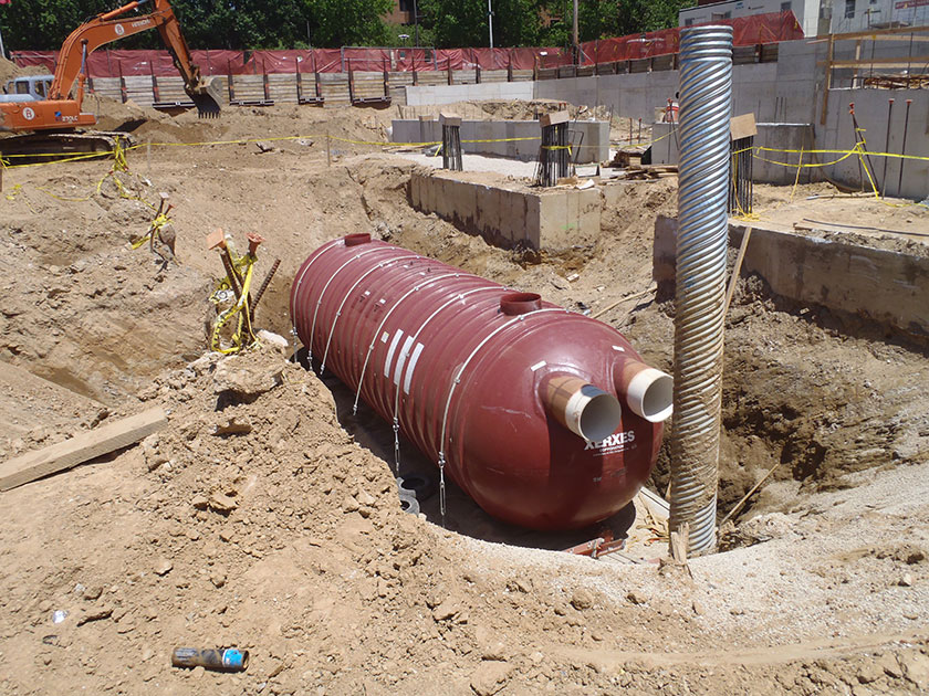
An example of a subsurface cistern installation in Philadelphia 4.5.6 Cistern maintenance guidance
Maintenance of cisterns focuses on the periodic removal of sediment and debris from pretreatment and storage areas. Sediment removal from tanks and pipes is typically conducted using vacuum or flushing systems. Guidance on the use and operation of vacuum or flushing sediment removal equipment is beyond the scope of this Manual; a maintenance professional should be contacted for additional details. As applicable, cistern maintenance procedures must meet Occupational Safety and Health Administration confined space entry requirements.
General recommended maintenance activities for cisterns are summarized in Table 4.5‑2.
Table 4.5‑2: Cistern maintenance guidelines
Early maintenance activity Frequency Inspect inlet structures, outlet structures,
and storage areas for trash and sediment accumulation.Monthly for the first year after installation to
determine ongoing maintenance frequencyOngoing maintenance activity Frequency Regularly clean out gutters, gutter screening, first-flush chamber, and catch basins to reduce sediment load to the cistern. Clean intermediate sump boxes, replace filters, and otherwise clean pretreatment areas in directly connected systems. As needed Remove sediment and debris from cisterns according to the manufacturer’s recommendations or the site-specific maintenance plan. As needed Test sediment for toxicants in compliance with current disposal requirements if land uses in the catchment include commercial or industrial zones, or if indications of pollution are present. As needed Brush the inside surfaces and thoroughly disinfect. Annually Prior to freezing weather, to avoid structural damage perform winterization of cisterns as per manufacturer’s requirements or design professional’s specifications. Annually Inspect cistern and control structures. Quarterly Remove floating debris and accumulated petroleum products from system and all components. Quarterly Maintain records of inspections and maintenance activity. Ongoing Periodic inspections and maintenance of cisterns must be conducted by a qualified professional. Maintenance requirements for cisterns that are part of rainwater harvesting systems vary according to reuse. Detailed maintenance guidance for rainwater harvesting systems is beyond the scope of this Manual.
The designer is referred to Section 4.10, Pretreatment, Section 4.11, Inlet Controls, and Section 4.12, Outlet Controls, for information on maintenance guidance for pretreatment, inlet controls, and outlet controls.
-
4.6 Blue Roofs
Download summaries of this SMP and its maintenance guidance, with quick reference information for clients and developers:
4.6.1 Blue roof introduction
Blue roofs, also known as controlled flow roof drain systems, are detention stormwater management practices (SMPs) that provide temporary storage and slow release of rainwater on a rooftop. Blue roof systems are an effective practice for controlling runoff from buildings with flat or mildly sloped roof surfaces. On blue roofs, water is temporarily detained on the roof surface using rooftop check dams or roof drain restrictors. In all cases, outflow is controlled using orifices prior to discharge, which is typically directed to the building’s storm drains, scuppers, or downspouts.
Since blue roofs function through detention and slow release alone, they neither add nor remove contaminants from stormwater; however, in a combined sewer area, they are acceptable pollutant-reducing practices for non-infiltrating Water Quality compliance. Blue roofs may also enable compliance with all remaining applicable Philadelphia Water Department (PWD) Stormwater Regulations (Stormwater Regulations), depending on outlet control sizing and structural and feasibility constraints. The designer is referred to Section 3.2.3 for information on using SMPs in series.
The design of blue roofs is not limited to the examples shown within this text. Successful stormwater management plans will combine appropriate materials and designs specific to each site.
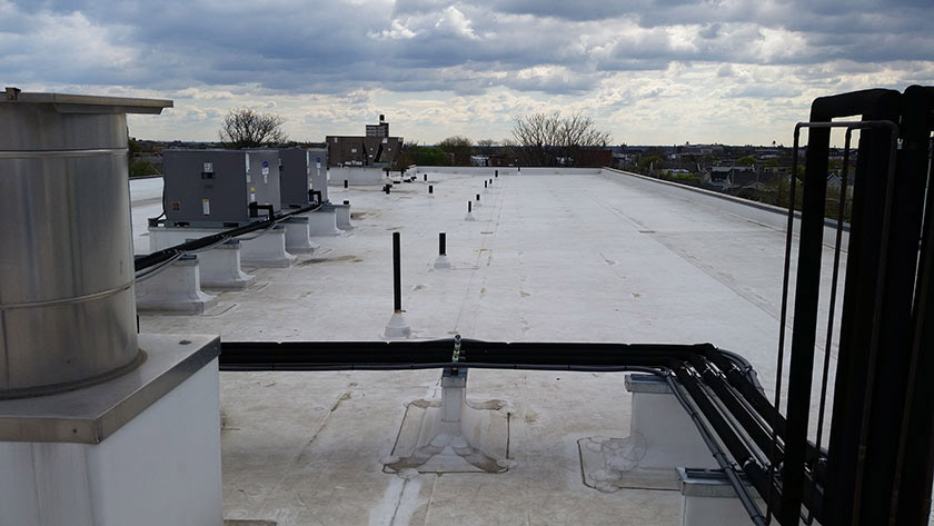
An example of a blue roof in Philadelphia When can blue roofs be used?
In combined sewer areas where infiltration is not feasible, blue roofs can be used to meet Water Quality release rate and pollutant-reducing requirements.
A blue roof can be considered for installation on a fully built-out or highly-constrained site. They can be installed on many types of roofs, including terraces, high-rise building roofs, and low podium or at-grade on-structure installations.
Blue roofs can also be installed as a Stormwater Retrofit on existing buildings with flat, mildly sloped, or terraced roofs after confirmation of adequate structural loading capacity, waterproofing, and protection of rooftop utilities.
Key advantages of blue roofs
- Manage stormwater runoff without occupying surface-level space
- Well-suited for sites at which roofs make up a large fraction of the total impervious area and for sites with ground-level space constraints
- Typically require no additional sewer connections besides the ones already provided for the building
- Easy to install if structural and waterproofing requirements are met
- Readily coupled with other SMPs, such as green roofs
- Can cost less than other SMPs
- Require no excavation
- Can provide educational benefits, especially when used at public and/or highly visible sites such as schools, recreation centers, libraries, etc.
- Assume less risk for projects within the floodplain
Key limitations of blue roofs
- Require regular inspection and maintenance of roof surface and roof drains, especially following high winds, as algae and debris can develop around roof drains and limit the rate of discharge
- Require strict adherence to regularly scheduled inspections because the maintenance needs are not easily visible
- May have limited storage capacity with slopes greater than 2%, likely necessitating installation of roof check dams and/or terraces to meet release rate requirements
- May result in increased cost or limited Stormwater Retrofit opportunities for existing buildings and structures due to additional loading associated with ponded water on roof
- Offer limited benefit on sites where roof area makes up only a small fraction of the total impervious area
- Do not improve aesthetics or provide the ancillary environmental benefits associated with vegetated SMPs, such as habitat creation and improved air quality
Key design considerations for blue roofs
- Blue roof systems utilizing controlled flow roof drains generally require flat or nearly flat roofs (e.g., less than 2% slope). It may be feasible to use check dams when slopes are higher than 2%.
- All building mechanical systems, roof furniture, and other appurtenances installed on the roof should not be compromised by roof ponding during rain events and should not cause damage to the roof membrane.
- Blue roof drains should be located away from overhead trees, if possible, to prevent leaf litter that would result in the clogging of the drains and additional or prolonged ponding on the rooftop.
- In order to prevent damage to the waterproofing membrane, access to the roof should be limited to maintenance needs only. Pedestal pavers can be used to separate the blue roof from the walking surface.
- It is recommended that an easily accessible vantage point be created to facilitate visual inspection of the blue roof system after rain events. If the storage volume has not drained within the intended drain down time, a more thorough inspection of the roof surface and/or outlet controls should be performed.
- For any blue roof that discharges onto an adjacent property, a drainage easement may be required and is recommended.
Blue roof types
On roofs with a parapet, roof drain restrictor systems detain water on the roof, with eventual discharge to the existing roof drain.
Roof check dam systems detain rainwater on rooftops or sections of rooftops without a parapet to increase storage volumes over roof areas with greater than 2% slope. These dams create temporary ponding areas during rain events before slowly discharging to the roof drain.
4.6.2 Blue roof components
Figure 4.6‑1: Blue roof with typical features
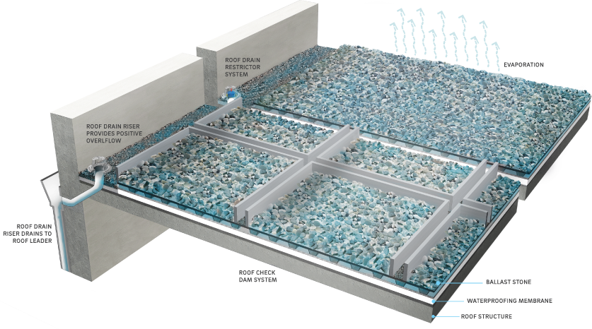
Inlet control component
Blue roofs that receive direct (1:1) rainfall only do not have inlet controls. For blue roofs that receive runoff from adjacent roof directly connected impervious area (DCIA), including additional roof levels, inlet control systems convey and control the flow of stormwater from the contributing catchment area to the SMP. The designer is referred to Section 4.11, Inlet Controls, for more information on inlet controls.
Storage area component
Blue roof storage areas temporarily hold stormwater until it can either evaporate or be released downstream at a controlled rate. The area dedicated to storage is dependent on the chosen blue roof system type.
Storage in roof drain restrictor systems is determined by the roof slope and geometry relative to the height of both the restrictors and parapets. The bulk volume occupied by all building mechanical systems, roof furniture, and appurtenances must also be factored into the storage volume calculations.
Storage in roof check dam systems is determined by the roof slope and associated area dedicated to ponding behind the dams. The bulk volume occupied by all building mechanical systems, roof furniture, and appurtenances must also be factored into the storage volume calculations
Blue roof storage areas are underlain by a waterproofing membrane. Numerous waterproofing membrane systems exist, including modified bitumen roofing (MBR), waterproof types of single-ply roofing, metal roof panels, spray polyurethane foam roofing, synthetic rubber membranes, thermoplastic membranes, and liquid-applied (including polyurethane-based and polymer-modified bituminous products) roofing. While high quality MBR systems (multiple MBR sheets tiled to reduce seam susceptibility) are suitable for blue roof usage, lower quality MBR systems (multiple layers of asphaltic sheets) are not recommended due to their seams that allow water to penetrate.
The durability and lack of seams achievable with a hot fluid applied, rubberized asphalt, fabric reinforced roofing system is well-suited for blue roofs. Cold liquid-applied systems are equally effective due to strict regulations on the use of the propane-fired devices for hot fluid systems.
Outlet control component
Outlet controls within a blue roof system can provide a range of functions, including the following:
- Meeting drain down time requirements;
- Controlling the rate of discharge from the SMP and limiting water surface elevations during various storm events; and/or
- Bypassing of flows from large storm events.
Outlet controls may include orifices, weirs, roof restrictors, risers, or impervious liners. The designer is referred to Section 4.12, Outlet Controls, for more information on outlet controls.
Roof drain restrictor blue roofs use a roof drain restrictor that is placed over the roof drain. These devices restrict flow through an orifice within the drain assembly, causing temporary ponding on the roof. They are typically purchased commercially through a manufacturer. Alternatively, a manufacturer can customize an orifice size for a specific development. The number and sizing of weirs and orifices are based on a predetermined relationship between the water depth approaching the drain and the flow rate entering the drain. The overflow mechanism of the device determines the maximum ponding depth.
For roof check dam systems, perforated aluminum T-section dams have been used to retain and slow-release rainwater. These inverted T-sections are weather sealed and secured to the roof structure, creating ponding areas behind the dam. Perforations in the dam allow for slow release. If not commercially available, these dams can be easily fabricated.
Inspection and maintenance access component
Safe and easy inspection and maintenance access to all major components within a blue roof system is critical to ensuring long-term performance. Dependent on roof height and slope, blue roof inspection and maintenance access components may consist of permanent or temporary safety monitoring systems, guardrail and safety net systems, warning line systems, and/or personal fall arrest systems. Inspection and maintenance access systems for blue roofs may also include long-term leak detection systems for locating and managing leaks.
4.6.3 Blue roof design standards
General design standards
- Structural loading must be considered for all blue roof designs, and blue roof design must be coordinated with a licensed structural engineer for both new building construction and retrofits to existing structures.
- The maximum allowable surface ponding depth is four to six inches. This will depend on loading capacity of the roof; six inches represents roughly 32 pounds per square foot of dead load.
- The maximum allowable drain down time is 72 hours after the 24‑hour storm event.
- Positive overflow must be provided for large storm events, up to and including the 100‑year, 24‑hour storm event, or, if the project is exempt from Flood Control, the ten‑year, 24‑hour storm. Overflow structures and pipes must be designed to convey at least the ten‑year, 24‑hour storm.
- Blue roof storage areas must be underlain by a waterproofing membrane.
Inlet control design standards
- The designer is referred to Section 4.11, Inlet Controls, for information on design standards for inlet control systems.
Storage area design standards
- The storage system must provide adequate storage to control release rates to meet all applicable Stormwater Regulations. The designer is referred to Section 3.2.3 for information on using SMPs in series.
- Designed storage capacity for blue roofs must account for structural and feasibility constraints. Connection to other SMPs can provide additional storage, if necessary.
- A porosity of 0.40 must be used for ballast stone.
- On roofs without ballast, designers must ensure that enough weight is provided to secure the waterproofing membrane. On roofs with ballast, designers must consider the depth and porosity of the ballast when calculating the potential storage volume.
Outlet control design standards
- Roof drain restrictors must be sized according to the desired release rate and ponding depth.
- The designer is referred to Section 4.12, Outlet Controls, for information on design standards for outlet control systems.
Inspection and maintenance access design standards
- Safe access to blue roofs must be provided for periodic cleaning, inspection, and maintenance by trained building personnel. Easy access must be provided to each of the outlet controls, low-flow discharge points, and overflow connections to permit removal of debris under saturated conditions.
- Seams, corners, penetrations, mounts or platforms for mechanical utilities, and any other areas of the roofing membrane where risk of leakage is highest, must be inspected for damage or failure and repaired in a manner consistent with the membrane material.
4.6.4 Blue roof material standards
Inlet control material standards
- The designer is referred to Section 4.11, Inlet Controls, for information on material standards for inlet control systems.
Storage area material standards
- Stone:
- Stone or gravel used for ballast within the stormwater storage area must be uniformly graded, clean-washed stone, either crushed or smooth. PWD defines “clean‑washed” as having less than 0.5% wash loss, by mass, when tested per the Association of State Highway and Transportation Officials (AASHTO) T-11 wash loss test. AASHTO No. 3 and No. 57 stone can meet this specification.
- Stone size must exceed the mesh size of the outlet control screen or slots. Ballast stone typically falls within the size range of 3/8 inch to 2 inches.
- Ballast must meet all American Society of Testing and Materials (ASTM) D1863 requirements for mineral aggregate used on built-up roofs.
- Other materials may be allowable pending PWD approval.
- Waterproof membrane:
- PVC, EPDM, and thermal polyolefin (TPO) are permitted.
- All waterproof membranes must meet appropriate ASTM specifications. PVC membranes must meet ASTM D4434 requirements, EPDM membranes must meet ASTM D4637 requirements, and TPO membranes must meet ASTM D6878 requirements.
- Waterproofing membrane must be fully waterproof with properly sealed seams, corners, and protrusions to prevent any intrusion of standing water above the membrane.
- Roofing membranes must meet all building code requirements and guidelines of the City of Philadelphia.
Outlet control material standards
- The designer is referred to Section 4.12, Outlet Controls, for information on material standards for outlet control systems.
4.6.5 Blue roof construction guidance
Proper construction of blue roofs is essential to ensure long-term functionality and reduce long-term maintenance needs. Blue roof systems are best installed by experienced roofing contractors with expertise in installing flat roof membranes over new or existing roof structures. A standard construction sequence for proper blue roof system installation is provided below. This can be modified to reflect different blue roof system applications or expected site conditions.
- Install waterproof membrane along the roof and parapet wall to a height at least six inches above the peak ponding elevation as per the SMP designs.
- Inspect for any irregularities that will interfere with drainage.
- Seal all edges, seams, corners, protrusions, and other anomalies in a watertight manner consistent with the installation specifications of the membrane manufacturer.
- Install outlet controls in a manner consistent with the City’s Building and Plumbing Codes and guidelines. The designer is referred to Section 4.12 for information on sizing and installation of outlet control systems. Outlet systems must include a bypass/overflow mechanism to permit rapid discharge when the storage volume of the blue roof system is exceeded.
4.6.6 Blue roof maintenance guidance
Maintenance of blue roof systems focuses on the periodic removal of sediment and debris from outlet and storage areas in order to prevent clogging and limit deterioration of the roof membrane. Maintenance activities can generally be performed by individual building owners or site maintenance staff as needed. The contractor responsible for the installation of the rooftop system should be contacted immediately if it is not performing as designed.
Maintenance of roof assembly and waterproofing membrane will be dependent on the assembly type, age, and quality of roof components. As with any roof system, periodic inspections should be performed to assure that repair or replacement is not necessary.
Blue roof components are relatively easy to maintain due to their simplicity and ease of access. In both the roof check dam and roof drain restrictor systems, maintenance activities are readily conducted at the roof surface. All restrictors and ponded areas must be accessible for periodic inspection and cleaning.
Problems with a blue roof system generally fall into two categories: (1) the system drains too slowly, resulting in buildup of excess water on the roof for extended periods of time, bypasses of the controlled flow roof drains, or bypasses/overflows during small rainfall events; or (2) the system drains too quickly, due to leaking or other issues, exceeding the design drain down rate. If problems persist, a licensed professional should be consulted.
General recommended maintenance activities for blue roof systems are summarized in Table 4.6‑1.
Table 4.6‑1: Blue roof maintenance guidelines
Early maintenance activity Frequency Inspect outlet structures, and storage areas for trash and sediment accumulation. Monthly for the first year after installation to determine ongoing maintenance frequency Ongoing maintenance activity Frequency Remove debris from drainage outlets and outlet screens to prevent clogging. During inspections or as needed to ensure performance Remove debris from secondary drainage/overflows. During inspections or as needed to ensure performance Remove excessive buildup of sediment around the outlet controls or within the storage cells. During inspections or as needed to ensure performance Inspect for leaks. During inspections or as needed to ensure performance Break up ice formation around outlets and overflows. As needed during winter months Maintain records of all inspections and maintenance activity. Ongoing The designer is referred to Section 4.12, Outlet Controls, for information on maintenance guidance for outlet controls.
-
4.7 Ponds and Wet Basins
Download summaries of this SMP and its maintenance guidance, with quick reference information for clients and developers:
4.7.1 Pond and wet basin introduction
Ponds and wet basins are earthen depressions constructed with a substantial permanent water pool to provide both temporary and long-term storage of stormwater runoff, and they can be used to attenuate peak flows and provide Water Quality treatment through both pollutant removal and slow release. These stormwater management practices (SMPs) attenuate peak flows through the use of an outlet control structure and provide storage capacity above the permanent pool, while water held within the system, including the permanent pool, is treated through a variety of physical, chemical, and biological processes. Wet basins can also achieve minimal volume reduction through evapotranspiration.
Wet basins are relatively effective at removing many common stormwater pollutants including suspended solids, heavy metals, total phosphorus, total nitrogen, and pathogens. The pollutant removal effectiveness varies by season and may be affected by the age of the wet basin. Detention basins are similar in function to ponds and wet basins with the exception that they lack these water quality benefits and are primarily used for peak rate control and extended detention.
Design of ponds and wet basins is not limited to the examples shown within this text. Successful stormwater management plans will combine appropriate materials and designs specific to each site.
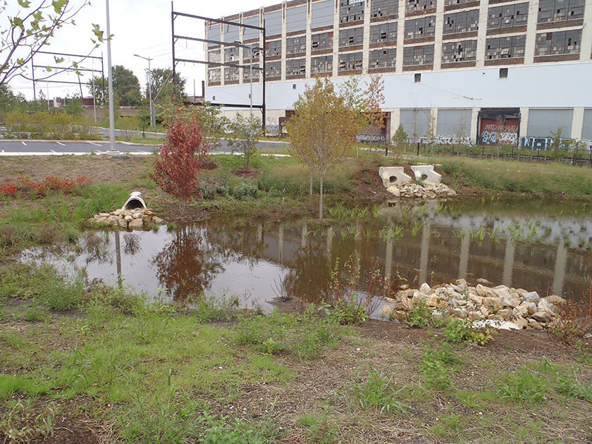
An example of a wet basin in Philadelphia When can ponds and wet basins be used?
Ponds and wet basins are capable of managing runoff in a variety of different settings, provided there is adequate space available for the SMP. They require a connection with shallow groundwater or a sufficient source of inflow to maintain the permanent pool.
Key advantages of ponds and wet basins
- Can be effective at providing Water Quality requirement treatment and flow attenuation while also providing aesthetic amenities and wildlife habitat
- Can easily be converted from a dry detention basin
- Can contribute to better air quality and help reduce urban heat island impacts
- Can provide educational benefits, especially when used at public and/or highly visible sites such as schools, recreation centers, libraries, etc.
Key limitations of ponds and wet basins
- Require a dedicated, large ground surface area
- May contain deep water, which can pose a safety hazard and may require fencing to restrict access
- Can sometimes attract geese and other wildlife that may conflict with the intended site use of surrounding areas
- Can provide a mosquito breeding habitat along shallow edges if not designed appropriately
Key design considerations for ponds and wet basins
- A berm placed on the downslope side of a mild slope can function as a forebay, helping retain stormwater and increasing capacity without additional excavation. The designer is referred to Section 4.10, Pretreatment, for more information on forebays.
- Secondary benefits, such as wildlife viewing areas and walking paths, can be incorporated into wet basin designs to enhance their value.
- Robust and diverse vegetation should be used along the perimeter of the pond to provide a buffer from surrounding areas.
- Smart plant selection for the site should be a focus. It is critical that plant materials are appropriate for soil, hydrologic, light, and other site conditions. The designer is referred to the list of native species in Appendix I. Ponding depth, drain down time, sunlight, salt tolerance, and other conditions should be taken into consideration when selecting plants. Turf grass is generally not recommended but may be acceptable provided the designer can demonstrate that it meets all applicable requirements. The designer is referred to Section 4.13, Landscaping, for additional landscaping guidance.
- For any pond or wet basin that discharges onto an adjacent property, a drainage easement may be required and is recommended.
4.7.2 Pond and wet basin components
Figure 4.7‑1: Ponds and wet basins with typical features
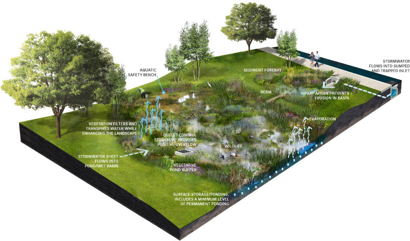
Pretreatment component
Pretreatment systems capture trash, sediment, and/or other pollutants from stormwater runoff before delivery to the storage area. Pretreatment needs will vary significantly depending on the contributing drainage area composition and use. Pretreatment can include structures such as sumped and trapped inlets, sediment/grit chambers or separators, media filters, inlet inserts, or other appropriate prefabricated or proprietary designs to remove sediment, floatables, and/or hydrocarbons from stormwater runoff prior to introduction to a pond or wet basin. While inlet hoods are preferred, permanent filter bags may be accepted for Stormwater Retrofit projects where existing inlets do not have hoods and inlet reconstruction is not feasible. In addition to sumped and trapped inlets, permanent filter bag inserts are required for sites that generate pollutants such as loading docks, material storage facilities, junk yards, and waste collection and disposal sites. Permanent filter bags will require frequent cleanings.
Pretreatment can also consist of filter strips, forebays, and swales. The designer is referred to Section 4.10, Pretreatment, for more information on pretreatment systems.
Inlet control component
Inlet control systems convey and control the flow of stormwater from the contributing catchment area to a pond or wet basin. Inlet control needs will vary depending on the design of stormwater conveyance systems and the site layout. The designer is referred to Section 3.4.2 for guidance on stormwater conveyance system design.
Inlet controls may include flow splitters, curbless design/curb openings, energy dissipaters, and inlets. The designer is referred to Section 4.11, Inlet Controls, for more information on inlet controls.
Storage area component
Storage areas within ponds and wet basins temporarily hold stormwater runoff until it can either evaporate, be used by plants through evapotranspiration, or be released downstream at a controlled rate, depending on the system design. The storage component of a pond or wet basin is provided typically by either excavating an area to create a depression, or by constructing berms around a low-lying area to create an impoundment. Ponding time provides water quality benefits by allowing larger debris and sediment to settle out of the water.
Storage areas within ponds and wet basins are designed with aquatic/safety benches. An aquatic/safety bench is a shallow, graded area that extends inward from the perimeter of the permanent pool boundary. This bench provides valuable wildlife habitat area and helps to minimize safety risks associated with the permanent pool by providing a shallow perimeter zone.
A pond buffer should extend outward from the permanent pool boundary in order to enhance habitat potential, improve aesthetics, reduce water temperatures, and improve overall pond health.
Vegetation component
Plant material in a pond or wet basin removes nutrients and stormwater pollutants through vegetative uptake and microbial community support, removes water through evapotranspiration, improves aesthetics, provides wildlife habitat, and helps to stabilize soil. Vegetation in and around a pond or wet basin also provides algal control and cooler water temperatures. The designer is referred to Section 4.13, Landscaping, for more information on landscaping.
Outlet control component
Outlet controls within a pond or wet basin can provide a range of functions, including the following:
- Meeting drain down time requirements;
- Controlling the rate of discharge from the SMP and limiting water surface elevations during various storm events; and/or
- Bypassing of flows from large storm events.
Outlet controls may include orifices, weirs, risers, level spreaders, or impervious liners. The designer is referred to Section 4.12, Outlet Controls, for more information on outlet controls.
Inspection and maintenance access component
Safe and easy inspection and maintenance access to all major components within a pond or wet basin is critical to ensuring long-term performance. Mildly sloping, stabilized, graded areas can provide access to surface storage areas for heavy equipment, which may be needed for sediment removal.
4.7.3 Pond and wet basin design standards
General design standards
- The maximum allowable drain down time is 72 hours after the 24‑hour storm event.
- Positive overflow must be provided for large storm events, up to and including the 100‑year, 24‑hour storm event, or, if the project is exempt from Flood Control, the ten‑year, 24‑hour storm. Overflow structures and pipes must be designed to convey at least the ten‑year, 24‑hour storm.
- The minimum allowable freeboard between the peak storage elevation during the 100‑year, 24‑hour storm event and the emergency spillway invert elevation is one foot.
- The minimum allowable distance between the emergency spillway crest elevation and the top-of-berm elevation is one foot.
- The minimum allowable basin length-to-width ratio is 2:1.
- The minimum allowable basin width is ten feet.
- The minimum allowable sediment forebay length is ten feet.
- The distance between the basin inflow and outflow points must be maximized.
- A Natural Resources Conservation Service curve number of 98 must be used for the area below the water surface elevation, where required for hydrologic calculations.
- All areas deeper than four feet must have two aquatic safety benches extending a combined total of 15 feet, at minimum, inward from the perimeter of the basin. One bench must be above the normal water surface elevation and extend up to the pond side slopes at a maximum slope of 10%. The other bench must be below the water surface extending into the pond at a 10% slope to a maximum depth of 18 inches.
- A dewatering mechanism must be provided for facilities that are not in connection with groundwater.
Pretreatment design standards
- Acceptable form(s) of pretreatment must be incorporated into design. Pretreatment of runoff from all inlets is required. At a minimum, this can be achieved through the use of sumps and traps for inlets, sump boxes with traps downstream of trench drains, and filter strips for overland flow.
- The designer is referred to Section 4.10, Pretreatment, for more information on design standards for pretreatment systems.
Inlet control design standards
- To prevent erosion, energy dissipaters, such as riprap stone, must be placed at all locations of concentrated inflow. Riprap aprons must be designed, and stone sizing must be determined, in accordance with the riprap apron design procedures in the latest edition of the Pennsylvania Department of Environmental Protection (PA DEP) Erosion and Sediment Pollution Control Program Manual.
- The designer is referred to Section 4.11, Inlet Controls, for more information on design standards for inlet control systems.
Storage area design standards
- The storage area must provide static storage for the Water Quality Volume (WQv) between the overflow elevation and the basin’s water surface. All permanent pool areas must be excluded from the SMP’s storage volume estimation. The minimum allowable ponding depth below the lowest outlet device is three inches.
- Ponds and wet basins can be designed with additional storage beyond the WQv and with outlet controls that allow all remaining applicable Philadelphia Water Department (PWD) Stormwater Regulations (Stormwater Regulations) to be met.
- Maximum side slopes for open storage areas as follows:
- All – 2(H):1(V) (The recommended side slope is 3(H):1(V))
- Mowed- 4(H):1(V) to avoid “scalping” by mower blades
- A minimum planting soil medium depth of 18 inches must be provided (under emergent planting zones only). The planting soil medium may be composed of on-site soils.
Vegetation design standards
- Plantings must be designed to minimize the need for mowing, pruning, and irrigation.
- Plants and trees that are appropriate for, and compatible with, the site conditions must be chosen. The designer is referred to Section 4.13, Landscaping, for more information on landscaping and Appendix I for plant lists.
- Care must be taken to ensure that the ponding area depth is appropriate for the size and species of the plants selected.
- The planting design must provide for at least 85% cover of the emergent vegetation zone (the area of the pond that is less than 18 inches deep) and buffer area.
- A vegetated pond buffer must extend outward 25 feet from the permanent pool.
- Ponds and wet basins must be planted with species tolerant of a range of inundation depths and periods. A wetland ecologist or other appropriate design professional should be consulted for guidance.
Outlet control design standards
- Energy dissipaters, such as riprap stone, must be placed at the end of the primary outlet to prevent erosion. Riprap aprons must be designed, and stone sizing must be determined, in accordance with the riprap apron design procedures in the latest edition of the PA DEP Erosion and Sediment Pollution Control Program Manual.
- The primary and low-flow outlets must be protected from clogging by an external trash rack.
- The emergency spillway must not direct flow toward neighboring properties.
- The designer is referred to Section 4.12, Outlet Controls, for information on design standards for outlet control systems.
Inspection and maintenance access design standards
- Stabilized vehicular access must be provided for sediment removal. Areas must be at least nine feet wide, have a maximum slope of 15%, and be stabilized as needed to provide load support for vehicles.
4.7.4 Pond and wet basin material standards
Pretreatment material standards
- The designer is referred to Section 4.10, Pretreatment, for information on materials standards for pretreatment systems.
Inlet control material standards
- The designer is referred to Section 4.11, Inlet Controls, for more information on material standards for inlet control systems.
Storage area material standards
- Planting soil medium:
- Hydrologic soil groups “C” and “D” are suitable, without modification, for underlying soils.
- If natural topsoil from the site is to be used, it must have at least 8% organic carbon content by weight in the A-horizon for sandy soils and 12% for other soil types.
- If planting soil is imported, it must be made up of equivalent proportions of organic and mineral materials.
Vegetation material standards
- Trees and shrubs must be freshly dug and grown in accordance with good nursery practice.
- Perennials, grass-like plants, and groundcover plants must be healthy, well-rooted specimens.
- A native grass/wildflower seed mix can be used as an alternative to groundcover planting. Seed mix must be free of weed seeds.
- Use of invasive plants is not permitted. All plants and trees must be appropriate and compatible with soil, hydrologic, light, and other site conditions. The designer is referred to Appendix I for plant lists.
Outlet control material standards
- The designer is referred to Section 4.12, Outlet Controls, for information on material standards for outlet control systems.
4.7.5 Pond and wet basin construction guidance
Construction of ponds and wet basins often encompasses substantial excavation and grading activities that require careful oversight to ensure appropriate SMP function. Some general construction guidelines are as follows:
- Pond excavation depths should account for any impervious liners, plant matter, and/or planting soil required.
- The subsoil must be free of hard clods, stiff clay, hardpan, ashes, slag, construction debris, petroleum hydrocarbons, and other undesirable materials and must not be frozen or in a muddy state.
- Place impervious liner, if needed, ensuring continuous contact with subgrade. Extreme care should be taken during installation of a geomembrane liner so that no damage is done to any part of the material. Construction equipment, gasoline driven generators, or cans of gas or solvent must not be placed on the geomembrane material. The geomembrane material must not be used as a work area to prepare patches or to store tools and supplies. Temporary wind anchorage by means of sandbags or tires must be provided during geomembrane installation. Nails, rebar, wire ties, or other metal materials shall not be used to hold geomembrane in position. Geomembrane seaming must be performed in accordance with ASTM D7408 (PVC) and ASTM D8580 (LLDPE, PP). Non-destructive and destructive testing of geomembrane seaming must be performed in accordance with ASTM D7700. Mechanical attachment of geomembrane to pipe penetrations or structures must be installed in accordance with ASTM D6497/D6497M‑02. Placement of overlying material must be performed in a manner that will not damage the geomembrane. Excessive wrinkling of the geomembrane must be prevented prior to or while covering the geomembrane, ensuring no permanent folds or wrinkles in the liner. Any damage to the geosynthetic material must be repaired immediately.
- During all phases of work, including transport and on-site handling, the plant materials must be carefully handled and packed to prevent injury and/or desiccation of the plants. Plant material should be kept from freezing and kept moist, cool, and covered so as to protect the plants from any precipitation, wind, and/or sun. Plants must be watered to maintain moist soil and/or plant conditions until accepted.
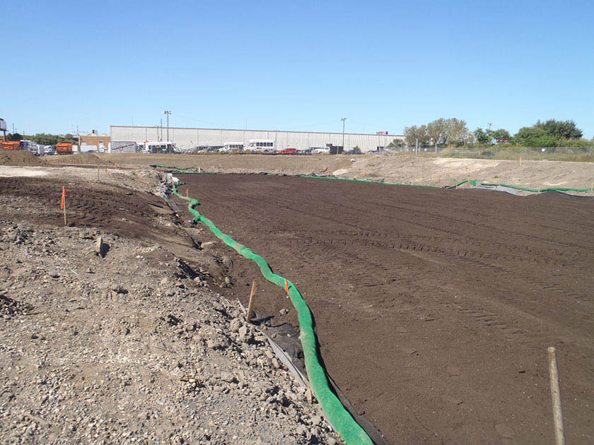
An example of a wet basin installation in Philadelphia 4.7.6 Pond and wet basin maintenance guidance
Maintenance of ponds and wet basins focuses on the periodic removal of sediment and debris from pretreatment and storage areas and prevention of outlet control clogging.
General recommended maintenance activities for ponds and wet basins are summarized in Table 4.7‑1.
Table 4.7‑1: Ponds and wet basins maintenance guidelines
Early maintenance activity Frequency Water vegetation at the beginning of each day for eight weeks after planting is completed. Daily for eight weeks after installation Water vegetation regularly to ensure successful establishment. Every four days during periods of four or more days without rain, June through August for the 24 months after installation Inspect vegetation for signs of disease or distress. Treat or replace, as necessary. Biweekly for the first year after installation Inspect inlet controls, outlet structures, and storage areas for trash and sediment accumulation. Remove debris and sediment, as necessary. Monthly for the first year after installation to determine ongoing maintenance frequency Ongoing maintenance activity Frequency Remove trash and debris from forebay, pond, and outlet structure. As needed Remove non-target/invasive vegetation. As needed Grassed areas require periodic prudent fertilizing, dethatching and soil conditioning. As needed Trees, shrubs, and other vegetative cover will require periodic maintenance such as fertilizing, pruning and pest control. As needed Mow/trim detention basin vegetation, excluding aquatic bench and buffer. As needed Treat basin for mosquito larvae if stagnant water remains for longer than 72 hours. As needed Dredge large volumes of sediment and organic debris from basin and forebay areas.
Accumulated sediment must never occupy greater than 50% of the forebay volume.As needed
(At least once every five to ten years*)Inspect outlet control structure for clogging. Quarterly and after every storm greater than one inch Replace filter bags for pretreatment devices. Ensure filter bag is installed properly. Quarterly Inspect SMP for potential problems, including subsidence, erosion, cracking, or tree growth on the embankment; damage to the emergency spillway; sediment accumulation around the outlet; inadequacy of the inlet/outlet channel erosion control measures; changes in the condition of the pilot channel; and erosion within the SMP and its banks. Semiannually Maintain records of all inspections and maintenance activity. Ongoing *The frequency of sediment removal depends on site conditions such as soil type and maintenance of site stabilization which influence the sediment load on the SMP. The designer is referred to Section 4.10, Pretreatment, Section 4.11, Inlet Controls, Section 4.12, Outlet Controls, and Section 4.13, Landscaping, for information on maintenance guidance for pretreatment, inlet controls, outlet controls, and landscaping.
-
4.8 Subsurface Detention
Download summaries of this SMP and its maintenance guidance, with quick reference information for clients and developers:
4.8.1 Subsurface detention introduction
Subsurface detention stormwater management practices (SMPs) are underground structures that are used to temporarily detain and release stormwater. They can include vaults, stone storage, pipe storage, and plastic grid storage.
Subsurface detention SMPs can be combined with other SMPs in series to meet the Philadelphia Water Department (PWD) Stormwater Regulations (Stormwater Regulations). The designer is referred to Section 3.2.3 for information on using SMPs in series.
Design of subsurface detention SMPs is not limited to the examples shown within this text. Successful stormwater management plans will combine appropriate materials and designs specific to each site.
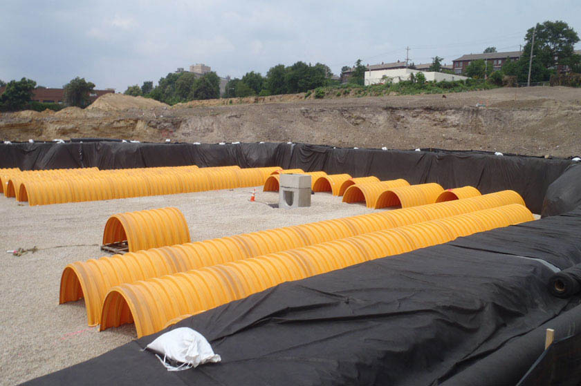
An example of a subsurface detention basin in Philadelphia When can subsurface detention be used?
Subsurface detention SMPs are suitable on sites where infiltration has been deemed infeasible and space constraints prevent the use of surface-level or rooftop SMPs. Provided that overburden loads and utility conflicts are evaluated, subsurface detention SMPs can be sited beneath lawns, recreational areas, parking lots, and other hardscape surfaces.
Key advantages of subsurface detention
- Manages stormwater runoff without occupying surface or rooftop space
- Can be sited, through flexible design options, beneath lawns, recreational areas, parking lots, buildings, or other impervious areas when space constraints exist
- Allows for easily adaptable footprints that can fit into almost any size space and be integrated into many different site layouts
Key limitations of subsurface detention
- May need to be combined with other SMPs to meet the Water Quality requirement
- Can be more costly and difficult to install and maintain than surface practices like bioretention SMPs
- Require strict adherence to regularly scheduled inspections because the maintenance needs are not easily visible
- Require additional maintenance costs due to access limitations and Occupational Safety and Health Administration (OSHA) requirements
- Does not improve aesthetics or provide the ancillary environmental benefits associated with vegetated SMPs, such as habitat creation and improved air quality
Key design considerations for subsurface detention
- Appropriate pretreatment of runoff should be provided to remove sediment and debris before discharging to a subsurface detention SMP. A pretreatment approach should be developed based on the SMP’s expected level of sediment loading and anticipated difficulty of sediment removal.
- Before using subsurface detention to comply with Water Quality release rate requirements, it must be adequately demonstrated that infiltration is not feasible on-site. The designer is referred to Section 3.3 for information on infiltration testing requirements.
- Subsurface chambers, crates, or arches can be used to increase void space and reduce SMP footprint; however, long-term maintenance should also be carefully considered when evaluating such systems. Subsurface vaults can be periodically cleaned using vacuum cleaning, whereas it is much more difficult to remove accumulated sediment from stone storage and grid storage systems.
- The SMP and maintenance access should be located in an area where maintenance and potential repairs can be conducted with minimal disturbance to surrounding uses.
- Areas of soil contamination or unstable soils should be avoided; however, in some cases, an impervious liner may be appropriate.
- For any subsurface detention SMP that discharges onto an adjacent property, a drainage easement may be required and is recommended.
Subsurface detention types
Subsurface detention SMPs can be designed in a variety of different ways, but commonly fit into the following four categories:
Underground storage vaults are buried concrete, fiberglass, or polyethylene chambers that temporarily store and release stormwater. The designer is referred to Section 4.5, Cisterns, for more information on the use of underground storage SMPs for rainwater harvesting.
Underground stone storage consists of buried stone beds wrapped in geotextile that temporarily store and release stormwater. Stone storage beds provide the least amount of storage volume per unit area among the subsurface detention types. Removing sediment from underground stone storage is difficult, which necessitates effective pretreatment.
Underground pipe and chamber storage consists of perforated plastic or metal pipes, or pipe-like linear chambers, that are placed in a stone bed to provide more storage per unit volume and temporarily store and release stormwater. Various pipe dimensions and shapes can be used to optimize the storage volume to meet the specific site requirements.
Underground plastic grid storage consists of buried plastic structures that can be stacked and inter-connected to form various shapes and sizes. Grid systems can provide as much as 95% void space for storage of stormwater.
4.8.2 Subsurface detention components
Figure 4.8‑1: Subsurface detention with typical features
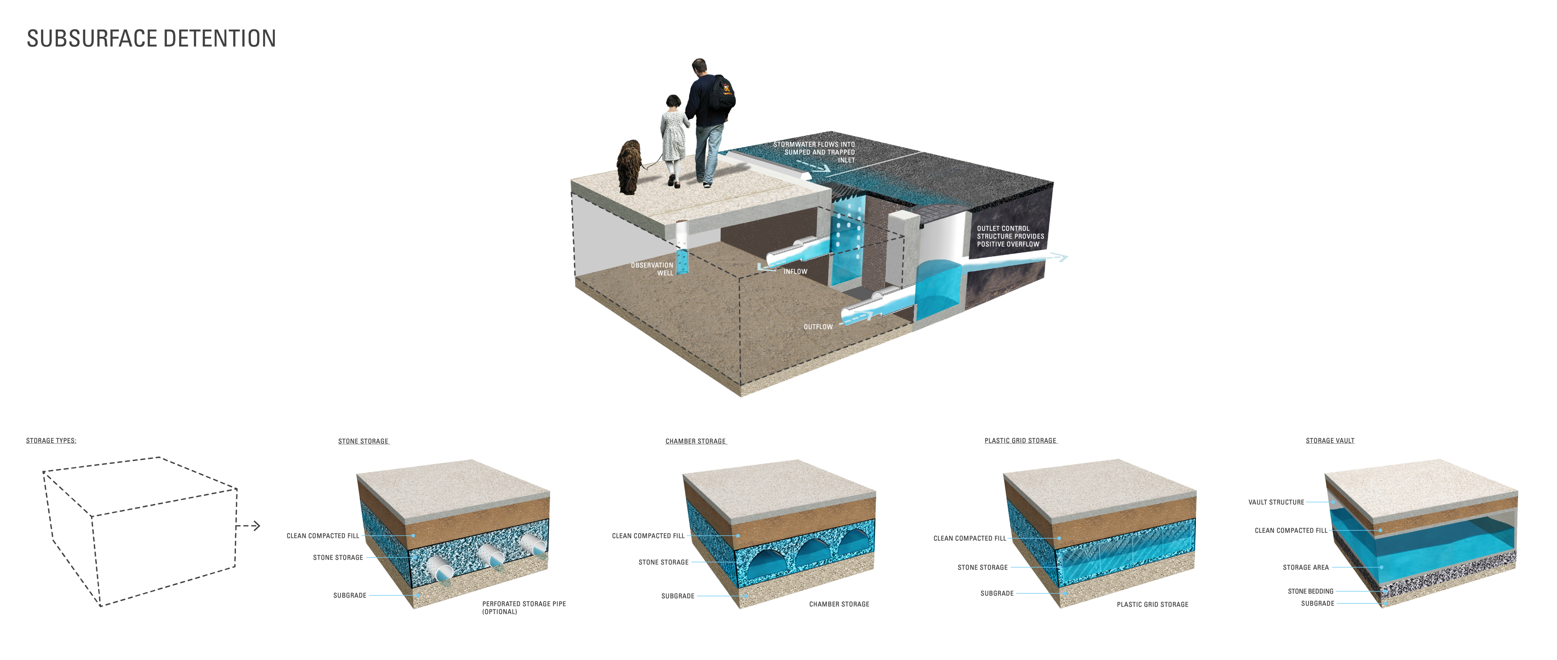
Pretreatment component
Pretreatment systems capture trash, sediment, and/or other pollutants from stormwater runoff before delivery to the storage area. Pretreatment needs will vary significantly depending on the contributing drainage area composition and use. Pretreatment can include structures such as sumped and trapped inlets, sediment/grit chambers or separators, media filters, inlet inserts, or other appropriate prefabricated or proprietary designs to remove sediment, floatables, and/or hydrocarbons from stormwater runoff prior to being conveyed to a subsurface detention SMP. While inlet hoods are preferred, permanent filter bags may be accepted for Stormwater Retrofit projects where existing inlets do not have hoods and inlet reconstruction is not feasible. In addition to sumped and trapped inlets, permanent filter bag inserts are required for sites that generate pollutants such as loading docks, material storage facilities, junk yards, and waste collection and disposal sites. Permanent filter bags will require frequent cleanings.
Some storage manufacturers have maintenance rows that qualify as pollutant-reducing practices. The designer is referred to this list of acceptable filter products and to Section 3.1.7 for more information on maintenance rows and pollutant-reducing practices, respectively.
Pretreatment can also consist of filter strips, forebays, and swales. The designer is referred to Section 4.10 for more information on pretreatment systems.
Inlet control component
Inlet control systems convey and control the flow of stormwater from the contributing catchment area to a subsurface detention SMP. Inlet control needs will vary depending on the design of stormwater conveyance systems and the site layout. The designer is referred to Section 3.4.2 for guidance on stormwater conveyance system design.
Inlet controls may include flow splitters, curbless design/curb openings, energy dissipaters, and inlets. The designer is referred to Section 4.11 for more information on inlet controls.
Storage area component
The storage component of a subsurface detention SMP is typically constructed of a stone-filled bed or trench, which may or may not incorporate pipes, arches, concrete vaults, crates, plastic grids, or other proprietary structures. The void spaces between the stones and/or structures store stormwater until it can be released downstream at a controlled rate.
A permanent pool of water may be incorporated to dissipate energy and improve the settling of particulate pollutants, in which case, the design may be referred to as a “wet underground detention SMP.”
Outlet control component
Outlet controls within a subsurface detention SMP can provide a range of functions, including the following:
- Meeting drain down time requirements;
- Controlling the rate of discharge from the SMP and limiting water surface elevations during various storm events; and
- Bypassing of flows from large storm events.
Outlet controls may include orifices, weirs, level spreaders, or low flow devices.
When coupled with the implementation of an acceptable pollutant-reducing practice, a subsurface detention SMP can be used to achieve a slow-release rate in order to fully comply with the Water Quality requirement on sites that cannot infiltrate in the combined sewer area. This ability to slowly release the discharge into PWD sewers or receiving waters can also be used to meet Channel Protection, Flood Control, and Public Health and Safety Release Rate requirements, if applicable.
Typically, release rates for slow-release systems are met using small orifices or other rate control devices. Additionally, the outlet control structure may require design and maintenance measures to avoid clogging. To accommodate these design mandates, PWD offers a design option in the form of an Underdrain Orifice Standard Detail (Figure 4.8‑2).
Figure 4.8‑2: Underdrain orifice standard detail
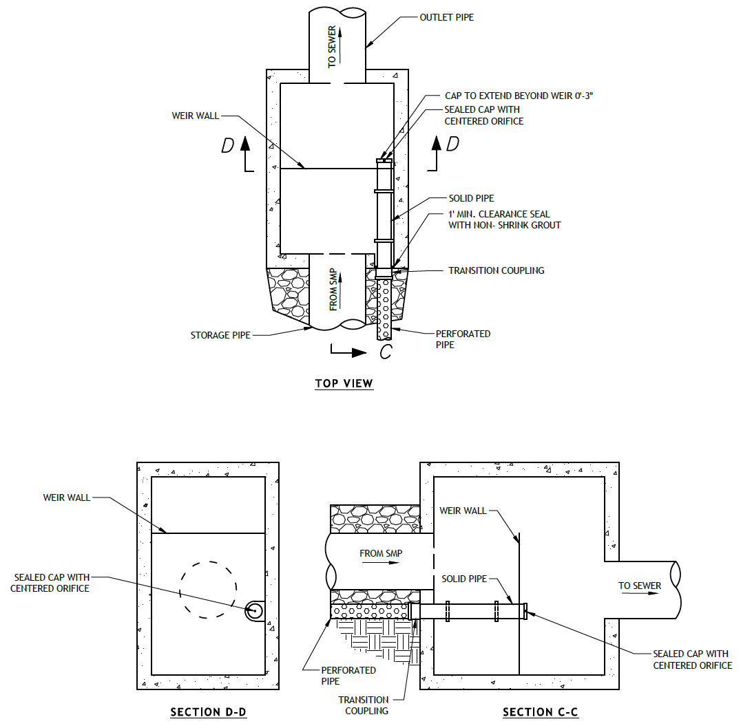
(The designer is referred to Appendix L to download Standard Detail CAD files.)
Inspection and maintenance access component
Safe and easy inspection and maintenance access to all major components within a subsurface detention SMP is critical to ensuring long-term performance. Inspection and maintenance access structures provide a portal to subsurface structures within a subsurface detention SMP. They most commonly consist of a panel, port, or manhole. Access points provide access to subsurface systems, both for inspections and routine maintenance, and for pumping water out of subsurface SMPs in cases of failure or severe damage. Manholes provide access for maintenance personnel and equipment to perform maintenance and inspections. Cleanouts provide access for hoses and vacuum equipment. Observation wells provide access to the bottom of subsurface systems for performance inspections and monitoring. Access structures may also serve additional functions, such as joining subsurface pipes.
4.8.3 Subsurface detention design standards
General design standards
- The maximum allowable drain down time is 72 hours after the 24‑hour storm event.
- Positive overflow must be provided for large storm events, up to and including the 100‑year, 24‑hour storm event, or, if the project is exempt from Flood Control, the ten‑year, 24‑hour storm. Overflow structures and pipes must be designed to convey at least the ten‑year, 24‑hour storm.
- Structural suitability for overburden support and traffic loading must be considered, where applicable.
- The minimum allowable distance between subsurface detention basins and any adjacent private property line is ten feet. This includes lined basins. Exceptions can be made for water-tight vaults with their own structural integrity, such as concrete or fiberglass vaults. It is acceptable for SMPs to be located directly adjacent to the public right-of-way (ROW).
- The minimum allowable distance between subsurface detention basins and any building or retaining wall is ten feet. This includes lined basins. The following requirements and exceptions apply:
- For existing and proposed buildings with basements, the setback is measured from the basement wall and may be waived if the basin is a water-tight vault with its own structural integrity, such as a concrete or fiberglass vault.
- For existing buildings without basements and existing retaining walls, the setback is measured from the foundation and may be waived if a signed and sealed geotechnical analysis is submitted that evaluates the impacts of residual infiltration and excavation on the existing foundation and determines it to be feasible.
- For proposed buildings without basements and proposed retaining walls, the setback is measured from the foundation and may be waived if the foundation is proposed to be designed with the basin’s proximity in mind.
Pretreatment design standards
- Acceptable form(s) of pretreatment must be incorporated into design. Pretreatment of runoff from all inlets is required. At a minimum, this can be achieved through the use of sumps and traps for inlets, sump boxes with traps downstream of trench drains, and filter strips for overland flow.
- The designer is referred to Section 4.10 for more information on design standards for pretreatment systems.
Inlet control design standards
- The designer is referred to Section 4.11 for information on design standards for inlet control systems.
Storage area design standards
- The storage area must provide adequate storage to control release rates to meet all applicable Stormwater Regulations. All permanent pool areas must be excluded from the SMP’s storage volume estimation.
- Bedding and foundations:
- Pipe, vault, grid and chamber storage areas must be adequately bedded with stone to prevent settling or subsidence.
- Bedding thickness must vary according to SMP requirements but must not be less than six inches.
- Over-excavation and replacement of loose or unstable subsurface material may be required if such conditions are encountered. A geotechnical engineer or other appropriate design professional should be consulted for additional guidance.
- Foundations/footers must be provided as warranted by system loading, geotechnical conditions, and manufacturer’s recommendations. Foundation designs must be performed by an appropriate design professional.
- The storage design must account for potential loading from vehicles, as appropriate, based on expected maximum active loading, including consideration for emergency vehicles.
- Subsurface detention SMPs must be designed with outlet controls that allow all applicable Stormwater Regulations to be met.
- Porosity values for storage volume calculations are as follows:
- Soil media: 0.20
- Sand: 0.30
- Stone: 0.40
- Void space provided by linear chamber systems, plastic grids, or other related structures must be as specified by the manufacturer and noted in supporting documentation.
- Stone must be separated from soil media by a geotextile or a pea gravel filter to prevent sand, silt, and sediment from entering the system.
Outlet control design standards
- The designer is referred to Section 4.12 for information on design standards for outlet control systems.
- Impervious liners should be avoided, but they may be necessary in areas where the threats of spills and/or groundwater contamination are likely. They must not be interrupted by structures within the basin footprint. Impervious liners must be continuous and extend completely up the sides of any structures that are located within the lined basin footprint to the ground surface. If additional liner material must be added to extend up the structures, the additional liner sections must be joined to the rest of the liner with an impervious seam per the manufacturers’ recommendation.
Inspection and maintenance access design standards
- Cleanouts, manholes, access panels, and other access features must be provided to allow unobstructed and safe access to SMPs for routine maintenance and inspection of inflow, outflow, underdrains, and storage systems.
- Observation wells must be provided for SMPs that include stone storage and must meet the following requirements:
- The observation well must be placed at the invert of the stone bed.
- The observation well must be located near the center of the stone bed system to monitor the level and duration of water stored within the SMP (drain down time). A minimum of six inches of clearance must be provided between the edge of the observation well’s concrete ring or frame and any nearby site features (curbing, tree pits, sidewalk edge, etc.). Plan view dimensioning for the proposed location of the observation well, relative to the boundaries of the SMP it lies within, must be provided on the plans.
- Adequate inspection and maintenance access to the observation well must be provided.
- An observation well located in a paved area must be outfitted with a cover and frame. The cover plate must be installed flush with the surrounding surface at finished grade, and grading should drain away from the observation well wherever possible. The solid section of the observation well must extend into the cover frame enough such that a bentonite/cement seal can be placed around the well within the frame, and a solid slip-on cap can be fitted onto the pipe end.
- An observation well located in an unpaved area must have a concrete ring or frame poured for support, with three lengths of rebar evenly spaced around the ring and three inches from its outer edge. The observation well should be located outside of the ponding area of any surface SMPs. If, due to space limitations, an observation well must be placed in the ponding area of a surface SMP, the concrete ring and well cover must extend three inches above the SMP’s maximum ponding depth.
- The observation well must include a slotted section within the storage layer of the SMP. The top of the slotted well section must extend to a minimum of six inches below the top of the SMP storage layer, and the slotted section must extend down the entire depth of the SMP.
- Access features for subsurface detention SMPs:
- Access features must be provided for all underground storage SMPs that are not stone storage beds.
- A sufficient number of access points in the system must be provided to efficiently inspect and maintain the storage area.
- For cast-in-place vault systems, access features must consist of manholes or grated access panels or doors. Grated access panels are preferred to maintain airflow. A minimum of 50 square feet of grate area is recommended for permanent pool designs.
- For grid storage or other manufactured systems, the manufacturer’s recommendations must be followed.
- Ladder access is required for vaults greater than four feet in height.
- Header pipes, at minimum 36‑inch diameter, connected to manholes at each corner of the subsurface detention SMP must be provided. Alternatively, smaller header pipes may be used if cleanouts are provided on the manifold/header pipe junction for each distribution pipe. The cleanouts must be on alternating sides of the SMP.
4.8.4 Subsurface detention material standards
Pretreatment material standards
- The designer is referred to Section 4.10 for information on materials standards for pretreatment systems.
Inlet control material standards
- The designer is referred to Section 4.11 for information on material standards for inlet control systems.
Storage area material standards
- Stone designed for stormwater storage must be uniformly graded, crushed, clean-washed stone. PWD defines “clean-washed” as having less than 0.5% wash loss, by mass, when tested per the American Association of State Highway and Transportation Officials (AASHTO) T-11 wash loss test. AASHTO No. 3 and No. 57 stone can meet this specification.
- Sand, if used, must be AASHTO M‑6 or American Society of Testing and Materials (ASTM) C‑33 sand and must have a grain size of 0.02 inches to 0.04 inches.
- Storage pipes:
- Pipe used within the subsurface detention SMP must have a minimum inner diameter of four inches.
- High-density polyethylene (HDPE) pipe must meet the specifications of AASHTO M252, Type S or AASHTO M294, Type S.
- Any pipe materials outside the SMP are to meet City Plumbing Code Standards.
- Geotextile must consist of polypropylene fibers and meet the following specifications (AASHTO Class 1 or Class 2 geotextile is recommended):
- Grab Tensile Strength (ASTM-D4632): ≥ 205 lbs
- CBR Puncture Strength (ASTM-D6241): ≥ 500 lbs
- Flow Rate (ASTM-D4491): ≥ 95 gal/min/ft2
- UV Resistance after 500 hrs. (ASTM-D4355): ≥ 70%
- Tear Resistance (ASTM-D4533): ≥ 80 lbs
- Heat-set or heat-calendared fabrics are not permitted.
Outlet control material standards
- The designer is referred to Section 4.12 for additional information on material standards for outlet control systems.
Inspection and maintenance access material standards
- Observation wells:
- The observation well must consist of slotted plastic pipe with a minimum inner diameter of four inches and a solid cap at the surface. The slotted section of the well must consist of PVC slotted well screen with 0.01‑inch slot size and an attached perforated PVC cap at the bottom.
- The observation well’s cover must be ductile iron in a gray iron frame.
- For an observation well located in an unpaved area, the well’s concrete ring must be a minimum of six inches wider in any dimension than the cover frame, of equal depth as the cover frame itself, and poured atop a minimum of six inches of AASHTO #57 stone bedding. A frame conforming to these minimum dimensions may be circular or square.
- Cleanouts must be made of material with a smooth interior having a minimum inner diameter of six inches. If the connecting pipe is eight inches in diameter or larger, then the cleanout must be eight inches in diameter.
4.8.5 Subsurface detention construction guidance
Proper construction of subsurface detention systems is essential to ensure long-term functionality and reduce long-term maintenance needs and costs. Subsurface detention SMPs are, by definition, buried; therefore, construction oversight is critical. At a minimum, verification of volumes, grades, and elevations must be performed prior to backfill.
- Provide erosion and sedimentation control protection on the site such that construction runoff is directed away from the proposed subsurface detention SMP. Sediment deposited in a subsurface detention SMP during construction, particularly a stone bed system, can reduce system performance. The designer is referred to the latest edition of the Pennsylvania Department of Environmental Protection (PA DEP) Erosion and Sediment Pollution Control Program Manual for information on design standards for erosion and sedimentation control practices.
- Excavate subsurface detention area to proposed depth, providing appropriate shoring and sheeting for deep excavations.
- Place impervious liner, if needed, ensuring continuous contact with subgrade. Extreme care should be taken during installation of a geomembrane liner so that no damage is done to any part of the material. Construction equipment, gasoline driven generators, or cans of gas or solvent must not be placed on the geomembrane material. The geomembrane material must not be used as a work area to prepare patches or to store tools and supplies. Temporary wind anchorage by means of sandbags or tires must be provided during geomembrane installation. Nails, rebar, wire ties, or other metal materials shall not be used to hold geomembrane in position. Geomembrane seaming must be performed in accordance with ASTM D7408 (PVC) and ASTM D8580 (LLDPE, PP). Non-destructive and destructive testing of geomembrane seaming must be performed in accordance with ASTM D7700. Mechanical attachment of geomembrane to pipe penetrations or structures must be installed in accordance with ASTM D6497/D6497M‑02. Placement of overlying material must be performed in a manner that will not damage the geomembrane. Excessive wrinkling of the geomembrane must be prevented prior to or while covering the geomembrane, ensuring no permanent folds or wrinkles in the liner. Any damage to the geosynthetic material must be repaired immediately.
- If using a stone storage bed, place geotextile, ensuring adequate overlap of 16 inches, or pea gravel, and storage stone.
- Set the pipe or chamber storage, if proposed, during installation of the stone storage bed, according to the plans.
- Place geotextile in accordance with manufacturer’s standards and recommendations.
- Secure geotextile at least four feet outside bed.
- Place stone in six- to eight‑inch lifts and lightly compact.
- Confirm storage area dimensions and outlet control elevations prior to backfill.
- If using a vault, pipe, or grid system, place geotextile or pea gravel, and stone base as described above.
- Place storage units. If using a manufactured system, install storage units in accordance with manufacturer’s recommendations.
- If using a cast-in-place vault system, perform form work, reinforcement, and concrete work in conformance with project specifications.
- Confirm the storage volume prior to backfill.
- Confirm and document invert elevations and dimensions for all structures such as vaults and pipes prior to backfill.
- Backfill to finished grade. Ensure backfill is properly compacted in accordance with specifications. Ensure backfill process does not disrupt pipe placement and configuration.
- Structures such as inlet boxes, reinforced concrete boxes, inlet controls, and outlet controls must be constructed according to manufacturer’s guidelines or design professional’s guidance.
- Once the site is permanently stabilized with vegetation, remove temporary erosion and sediment control measures.
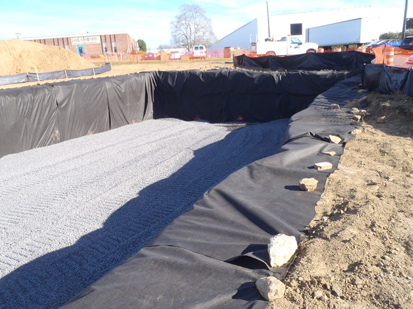
An example of a subsurface detention basin installation in Philadelphia 4.8.6 Subsurface detention maintenance guidance
Maintenance of subsurface detention SMPs requires the periodic removal of sediment and debris from pretreatment and storage areas and the prevention of outlet control clogging. Sediment removal from vaults, chambers, and pipes is typically conducted using vacuum or flushing systems. Guidance on the use and operation of vacuum or flushing sediment removal equipment is beyond the scope of this Manual; a maintenance professional should be contacted for additional details. As applicable, subsurface detention SMP maintenance procedures must meet OSHA confined space entry requirements.
General recommended maintenance activities for subsurface detention systems are summarized in Table 4.8‑1.
Table 4.8‑1: Subsurface detention maintenance guidelines
Early maintenance activity Frequency Inspect erosion control and flow spreading devices until soil settlement and vegetative establishment of contributing areas has occurred. Biweekly Inspect inlet controls, outlet structures, and storage areas for trash and sediment accumulation. Remove debris and sediment, as necessary. Monthly for the first year after installation to determine ongoing maintenance frequency Ongoing maintenance activity Frequency Regularly clean out gutters and catch basins to reduce sediment load to detention system. Clean intermediate sump boxes, replace filters, and otherwise clean pretreatment areas in directly connected systems. As needed Remove sediment and debris from subsurface detention SMP sedimentation chamber, as applicable, when the sediment zone is 3/4 full. Sediment and debris buildup may need to be removed by a professional. Consult with a professional, as necessary. As needed Remove sediment and debris from pipe/vault systems. Sediment depth is not to reach a maximum depth of four inches below the SMP’s outlet invert elevation. Removal of sediment from grid systems must be per manufacturer’s recommendations or as per the site-specific maintenance schedule. As needed Replace filter bags for pretreatment devices. Ensure filter bag is installed properly. Quarterly Inspect subsurface detention facility and control structures. Quarterly Remove floating debris and accumulated petroleum products from system and all components. Quarterly Maintain records of all inspections and maintenance activity. Ongoing The designer is referred to Section 4.10, Pretreatment, Section 4.11, Inlet Controls, and Section 4.12, Outlet Controls, for information on maintenance guidance for pretreatment, inlet controls, and outlet controls.
-
4.9 Media Filters
Download summaries of this SMP and its maintenance guidance, with quick reference information for clients and developers:
4.9.1 Media filter introduction
Media filters (also referred to as “filters” in this section) are structures or excavated areas containing a layer of sand, compost, organic material, peat, or other filter media. They reduce pollutant levels in stormwater runoff by filtering sediments, metals, hydrocarbons, and other pollutants. Filtered stormwater is then released to a sewer, receiving water, or downstream stormwater management practice (SMP). Media filters are designed to allow higher rates of stormwater flow than traditional filters. Sand and other rapid filter media enable smaller SMP footprints by allowing for faster filtration of stormwater.
Media filters can be combined with other SMPs in series to meet the Philadelphia Water Department (PWD) Stormwater Regulations (Stormwater Regulations). The designer is referred to Section 3.2.3 for information on using SMPs in series. Facilitating evapotranspiration, vegetated media filters are useful in meeting the Water Quality requirement when placed upstream of a non-infiltrating SMP. Non-vegetated media filters can assist in meeting the Water Quality requirement when placed upstream or downstream of a non-infiltrating SMP. For Stormwater Retrofits, media filters are needed for subsurface detention systems in the Municipal Separate Storm Sewer System (MS4).
The design of media filters is not limited to the examples provided within this text. Successful stormwater management plans will combine appropriate materials and designs specific to each site. Other types of prefabricated or proprietary filters such as water quality inserts fitted within inlets are available, but they are only to be used as pretreatment and are not considered SMPs.
Filters are evaluated on a project-specific basis since site conditions, such as sediment loading and/or drainage area size, can impact a product’s ability to meet Stormwater Regulations. Third-party certification of all performance claims is strongly encouraged for all prefabricated and proprietary devices. Examples of third-party certification programs include the New Jersey Department of Environmental Protection (NJDEP) and the Washington State Department of Ecology. The NJDEP certification uses the New Jersey Center for Advanced Technology (NJCAT) verification as conducted according to the Technology Acceptance and Reciprocity Partnership (TARP) Protocol. Washington State Department of Ecology uses the Technology Assessment Protocol – Ecology (TAPE). In addition to all certifications and laboratory test data, all performance claims should be supported by field test data where possible. PWD does not endorse the use of specific third-party certification programs, and specific programs are mentioned as examples only. PWD has developed a list, accessible on the PWD Development Services Resource Directory, of filter products that may be used to comply with the Stormwater Regulations. PWD allows the use of monitoring programs in lieu of, or in addition to, third-party certification.
The designer should note that there may be situations where PWD’s compliance requirements are more restrictive than a manufacturer’s specifications for a particular product; in these scenarios, the designer must engineer a solution that satisfies PWD standards.
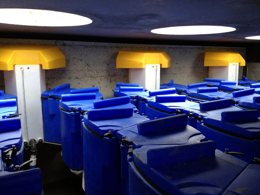
An example of a media filter in Philadelphia When can media filters be used?
Media filters can be used on sites where vegetated SMPs are impractical due to limited surface area or other constraints. They can assist applicants in meeting the Water Quality requirement where infiltration is not feasible. Filters may be used alone in separate sewer areas, or upstream or downstream of detention practices as part of a series approach in combined sewer areas, to meet multiple Stormwater Regulations.
Key advantages of media filters
- Have highly flexible designs and configurations that can be useful in meeting the Water Quality requirement where space-constrained, highly developed, or otherwise challenging locations prevent the use of traditional surface-level or rooftop SMPs, and infiltration is not feasible
- Can be designed to be visible from the surface or completely subsurface, located beneath parking lots or other impervious areas
Key limitations of media filters
- Do not offer, when non-vegetated, many of the ancillary benefits associated with surface vegetated SMPs, including aesthetic value, improved air quality, and habitat creation
- Do not reduce the volume of stormwater runoff like bioretention basins and green roofs do
- May have sizing requirements that result in large footprints due to filtration rates for filter media such as sand
Key design considerations for media filters
- A primary design consideration for filters is site suitability. The use of a bioretention SMP should first be considered before selecting a media filter. Bioretention SMPs provide the same, or better, level of Water Quality treatment, provide a range of other economic and aesthetic benefits, and are typically easier to access and maintain.
- Philadelphia’s low temperatures are below freezing for approximately four months every year, and surface filtration may not function as well in the winter. Design options that allow direct subsurface discharge into filter media during cold weather may help overcome this condition.
- Filter media should be selected and sized to match the required rate of stormwater flow for the SMP. The designer should carefully consider the filtration rate of the media and the available storage volume in order to size the SMP.
- The maintenance access that is required for the filter system must be considered. Filter systems require frequent maintenance and may require different maintenance equipment than other SMPs.
- Proprietary media filters may inherently comply with many of the following design and material standards, in which case, submission of appropriate supporting documentation is critical.
- For any media filter that discharges onto an adjacent property, a drainage easement may be required and is recommended.
4.9.2 Media filter components
Figure 4.9‑1: Media filter with typical features
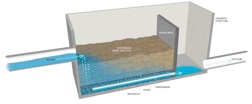
Pretreatment component
Pretreatment systems capture trash, sediment, and/or other pollutants from stormwater runoff before delivery to the storage area. Pretreatment needs will vary significantly depending on the contributing drainage area composition and use. Pretreatment can include structures such as sumped and trapped inlets, sediment/grit chambers or separators, inlet inserts, or other appropriate prefabricated or proprietary designs to remove sediment, floatables, and/or hydrocarbons from stormwater runoff prior to being conveyed to a filter system.
Pretreatment can also consist of filter strips, forebays, and swales. The designer is referred to Section 4.10 for more information on pretreatment systems.
Inlet control component
Inlet control systems convey and control the flow of stormwater from the contributing catchment area to a filter SMP. Inlet control needs will vary depending on the design of stormwater conveyance systems and the site layout. The designer is referred to Section 3.4.2 for guidance on stormwater conveyance system design.
Inlet controls may consist of flow splitters, curbless design/curb openings, energy dissipaters, and inlets. The designer is referred to Section 4.11 for more information on these types of inlet controls.
Storage area component
Storage areas within filter systems temporarily hold stormwater runoff before it can either pass through the filter media or be released downstream, depending on the system design and the size of the storm event. Storage for media filter systems can be located either above or below the ground surface. Surface storage is typically constructed by either excavating an area to create a depression or by erecting berms around a low-lying area to create an impoundment. Subsurface storage areas are typically constructed by excavating a trench or chamber below grade, lining it with concrete or another impermeable material, and constructing a cover over the storage area. Filter media, most typically sand, is contained within storage areas.
Outlet control component
Outlet controls in a filter system control the high-water level in the SMP and regulate overflow, either into an existing drainage network or into another SMP. Outlet controls can provide a range of functions, including:
- Meeting drain down time requirements, and/or
- Bypassing of flows from large storm events.
Outlet controls may consist of orifices, weirs, underdrains, level spreaders, impervious liners, micro siphon drain belts, or low flow devices. The designer is referred to Section 4.12 for more information on these types of outlet controls.
Inspection and maintenance access component
Safe and easy inspection and maintenance access to all major components in a media filter system is critical to ensuring long-term performance. Inspection and maintenance access structures provide a portal to subsurface structures within a filter system. They most commonly consist of a panel or manhole. Manholes or panels provide access for maintenance personnel and equipment to perform maintenance and inspections. Filter structures may require lift access or special equipment to perform the required maintenance. Large openings may be necessary to properly maintain the filters.
4.9.3 Media filter design standards
General design standards
- The following information must be submitted for each proposed media filter as part of the applicant’s Post‑Construction Stormwater Management Plan (PCSMP) Review Phase Submission Package. Preliminary consultations with PWD prior to submission are encouraged.
- Inflow and outflow event mean concentrations and percent removals for Total Suspended Solids (TSS) for sand/media filters (Designs must demonstrate a maximum effluent event mean concentration of 15 milligrams per liter for TSS at a point of analysis (POA) downstream of the SMP);
- Third-party certifications for proprietary media filters;
- Hydrologic and hydraulic model files, if applicable;
- Product specifications for proprietary media filters;
- Manufacturer’s guidelines for installation for proprietary media filters;
- Construction sequence; and
- Maintenance requirements, including product life and replacement schedule, if applicable.
- The maximum allowable drain down time is 72 hours after the 24‑hour storm event.
- The filter footprint must be sized pursuant to filter media flow-through rate.
- Positive overflow must be provided for large storm events. All systems must include overflow structures and pipes designed to convey at least the ten‑year, 24‑hour storm event.
- Filters without detention must be able to convey the ten‑year, 24‑hour storm event.
- Filters with detention must be designed to safely store and/or convey the 100‑year, 24‑hour storm event, or, if the project is exempt from Flood Control, the ten‑year, 24‑hour storm.
Pretreatment design standards
- For proprietary media filters, the manufacturer’s design guidance must be followed when determining appropriate pretreatment.
- Acceptable form(s) of pretreatment must be incorporated into design. Pretreatment of runoff from all inlets is required. At a minimum, this can be achieved through the use of sumps and traps. The designer is referred to Section 4.10, Pretreatment, for more information on design standards for pretreatment systems.
Inlet control design standards
- For proprietary media filters, the manufacturer’s design guidance must be followed when configuring the inlet controls.
- The designer is referred to Section 4.11, Inlet Controls, for information on design standards for inlet control systems.
Storage area design standards
- For proprietary media filters, the manufacturer’s design guidance must be followed when sizing the filter.
- The filter system must provide enough storage to allow the Water Quality storm to flow through the filter media. Upstream SMPs can be used to store this flow.
- When SMPs are used in series, the storage areas for all SMPs must provide cumulative static storage for the Water Quality Volume (WQv), but there is no minimum storage requirement for each individual SMP used in series.
- SMPs can be designed with additional storage beyond the WQv and with control structures that meet all remaining applicable Stormwater Regulations. Sand and peat media are acceptable for use in filters. The designer is referred to the material standards in this section for details on these approved mixtures. Other media mixtures may be approved on a case-by-case basis by PWD.
- Porosity values for storage volume calculations are as follows:
- Soil media: 0.20
- Sand: 0.30
- Stone: 0.40
- Porosity values of any proprietary rapid media should be obtained from the appropriate manufacturer.
- Surface Area
- Filters must have a minimum surface area as computed by the following equation:
Where: Af = surface area of the filter (square feet);
WQv = Water Quality Volume, the 1.5‑inch Water Quality Volume over directly connected impervious area (DCIA) (cubic feet); and
k = saturated hydraulic conductivity of the filter media (feet per day) - When computing surface area, use a filtration rate of two inches per hour for sand and soil (accounting for the reduction in filtration rates for sand over time due to build-up of fine material)
- Determination of filtration rate for proprietary or mixed media must be obtained from manufacturers or from evaluation of similar applications. High filtration rates at installation associated with some media types may yield small required surface area values. The designer must, however, account for the potential for filter systems to clog over time and must therefore adjust the assumed filtration rate to account for this
- Filters must have a minimum surface area as computed by the following equation:
- The minimum allowable filter media depth is 18 inches (greater depths may be used but do not alter filter sizing requirements).
- Stone cannot be used as filter media, but it can be used within filter systems to provide additional storage and must be provided as bedding for underdrains.
- Bedding and foundations:
- Pipe, vault, grid and chamber storage areas must be adequately bedded with stone to prevent settling or subsidence.
- Bedding thickness must vary according to system requirements but must not be less than six inches.
- Over-excavation and replacement of loose or unstable subsurface material may be required if such conditions are encountered. A geotechnical engineer or other appropriate design professional should be consulted for additional guidance.
- Foundations/footers must be provided as warranted by system loading, geotechnical conditions, and manufacturer’s recommendations. Foundation designs must be performed by an appropriate design professional.
- The storage design must account for potential loading from vehicles, as appropriate, based on expected maximum active loading, including consideration for emergency vehicles.
- The system must have a level bottom and use a terraced system, if installed along a slope.
Outlet control design standards
- For proprietary media filters, the manufacturer’s design guidance must be followed when configuring the outlet controls.
- Impervious liners are required for all filter systems not contained in impermeable structures. They must not be interrupted by structures within the filter footprint. Impervious liners must be continuous and extend completely up the sides of any structures that are located within the lined filter footprint to the ground surface. If additional liner material must be added to extend up the structures, the additional liner sections must be joined to the rest of the liner with an impervious seam per the manufacturers’ recommendation.
- Underdrains must be provided for all non-infiltrating systems and must meet the following requirements:
- Underdrains must be surrounded by a sand layer or stone to filter sediment and facilitate drainage.
- The minimum allowable depth of a sand or stone filter layer above and beneath the underdrain is six inches.
- Underdrains must be surrounded by a geotextile fabric if sand is used.
- The outlet pipe of an outlet control structure must have an invert at or below the invert of the underdrain. Setting the outlet pipe invert at a minimum of 7.5 inches below that of the underdrain is recommended.
- For filters located in the separate sewer area, where infiltration is infeasible, flow through the underdrain may be modeled as exfiltration at a rate of two inches per hour for sand media and at an appropriate rate for other filter media, then routed through the underdrain system. This exfiltration flow must be routed through the primary outlet of the filter, not discarded from the stormwater model. Determination of filtration rate for proprietary or mixed media must be obtained from the manufacturer or from evaluation of similar applications.
- The designer is referred to Section 4.12, Outlet Controls, for information on design standards for outlet control systems.
Inspection and maintenance access design standards
- For proprietary media filters, the manufacturer’s design guidance must be followed for inspection and maintenance access.
- Manholes, access panels and other access features must be provided to allow unobstructed and safe access to SMPs for routine maintenance and inspection of inflow, outflow, underdrains, and storage systems.
- Access features for underground storage SMPs within which filters may be contained:
- Access features must be provided for all underground storage SMPs that are not stone storage beds.
- A sufficient number of access points in the SMP must be provided to efficiently inspect and maintain the storage area.
- For cast-in-place vault systems, access features must consist of manholes or grated access panels or doors. Grated access panels are preferred to maintain airflow.
- Lifts or other equipment may be necessary for maintaining the filter media.
- Large access points may be required for maintaining/replacing the filter media.
- Ladder access is required for vaults greater than four feet in height.
4.9.4 Media filter material standards
Pretreatment material standards
- The designer is referred to Section 4.10, Pretreatment, for materials standards for pretreatment systems.
Inlet control material standards
- The designer is referred to Section 4.11, Inlet Controls, for materials standards for inlet control systems.
Storage area material standards
- Stone
- Stone designed for stormwater storage must be uniformly graded, crushed, clean-washed stone. PWD defines “clean-washed” as having less than 0.5% wash loss, by mass, when tested per the American Association of State Highway and Transportation Officials (AASHTO) T-11 wash loss test. AASHTO No. 3 and No. 57 stone can meet this specification.
- Stone must be separated from filter media by a geotextile or a pea gravel filter.
- Sand
- Sand used as filter media must be clean, medium to fine sand and have organic material meeting the specifications of AASHTO M‑6 (grain size of 0.02 to 0.04 inches) or American Society of Testing and Materials (ASTM) C‑33.
- At a minimum, applicants must demonstrate that the sand filter is capable of generating a maximum effluent EMC of 15 milligrams per liter for TSS accumulated at a POA downstream of the SMP.
- Other filter media
- Prior to use of any prefabricated, proprietary, or mixed filter media, the designer must carefully review design specifications and vendor information to assess performance, maintenance, longevity, and third-party verification.
- Peat must have an ash content of less than 15%, a pH range of 3.3 to 5.2, and a loose bulk density range of 0.12 g/cc to 0.14 g/cc.
- Filter media other than sand or peat may be used in certain cases, if approved for use by PWD. Approvals are granted on the basis of a case-by-case review by PWD based on information submitted by the applicant. At a minimum, applicants must demonstrate that the filter media is capable of generating a maximum effluent EMC of 15 milligrams per liter for TSS accumulated at a POA downstream of the SMP, meets all other filter design and water quality specifications set forth in this section, and has a demonstrated record of high performance within urban settings.
- Geotextile must consist of polypropylene fibers and meet the following specifications (AASHTO Class 1 or Class 2 geotextile is recommended):
- Grab Tensile Strength (ASTM-D4632): ≥ 205 lbs
- CBR Puncture Strength (ASTM-D6241): ≥ 500 lbs
- Flow Rate (ASTM-D4491): ≥ 95 gal/min/ft2
- UV Resistance after 500 hours (ASTM-D4355): ≥ 70%
- Tear Resistance (ASTM-D4533): ≥ 80 lbs
- Heat-set or heat-calendared fabrics are not permitted.
Outlet control material standards
- Underdrains must be made of continuously perforated high-density polyethylene (HDPE) plastic piping with a smooth interior and a minimum inner diameter of four inches. HDPE pipe must meet the specifications of AASHTO M252, Type S or AASHTO M294, Type S.
- Stone used for filter underdrains must be uniformly graded, clean-washed stone, either crushed or smooth. PWD defines “clean-washed” as having less than 0.5% wash loss, by mass, when tested per the AASHTO T-11 wash loss test.
- Sand, if used for filter underdrains, must be with AASHTO M‑6 or American Society of Testing and Materials (ASTM) C‑33 sand and must have a grain size of 0.02 inches to 0.04 inches.
- The designer is referred to Section 4.12, Outlet Controls, for information on material standards for outlet control systems.
4.9.5 Media filter construction guidance
Proper construction of filter systems is essential to ensure long-term functionality and reduce long-term maintenance needs.
- Provide erosion and sedimentation control protection on the site such that construction runoff is directed away from the proposed filter system. Sediment deposited in a filter system during construction, particularly a stone bed system, can reduce system performance. The designer is referred to the latest edition of the Pennsylvania Department of Environmental Protection (PA DEP) Erosion and Sediment Pollution Control Program Manual for information on design standards for erosion and sedimentation control practices.
- Excavate filter area to proposed depth, providing appropriate shoring and sheeting for deep excavations.
- For excavated systems, place impermeable liner ensuring continuous contact with subgrade. Extreme care should be taken during installation of a geomembrane liner so that no damage is done to any part of the material. Construction equipment, gasoline driven generators, or cans of gas or solvent must not be placed on the geomembrane material. The geomembrane material must not be used as a work area to prepare patches or to store tools and supplies. Temporary wind anchorage by means of sandbags or tires must be provided during geomembrane installation. Nails, rebar, wire ties, or other metal materials shall not be used to hold geomembrane in position. Geomembrane seaming must be performed in accordance with ASTM D7408 (PVC) and ASTM D8580 (LLDPE, PP). Non-destructive and destructive testing of geomembrane seaming must be performed in accordance with ASTM D7700. Mechanical attachment of geomembrane to pipe penetrations or structures must be installed in accordance with ASTM D6497/D6497M‑02. Placement of overlying material must be performed in a manner that will not damage the geomembrane. Excessive wrinkling of the geomembrane must be prevented prior to or while covering the geomembrane, ensuring no permanent folds or wrinkles in the liner. Any damage to the geosynthetic material must be repaired immediately.
- If using a stone storage bed in fill beneath the filter:
- Place geotextile, ensuring adequate overlap of 16 inches, or pea gravel, and storage stone.
- Set the underdrain during placement according to the plans.
- Place geotextile in accordance with manufacturer’s standards and recommendations.
- Secure geotextile at least four feet outside bed.
- Place stone in six-to-eight inch lifts and lightly compact.
- Confirm storage elevations prior to backfill.
- Place geotextile, ensuring adequate overlap of 16 inches, or pea gravel, and storage stone.
- If the filter is to be placed within a vault or concrete structure:
- Place stone base beneath vault.
- Place vault. If using a manufactured system, install vault in accordance with manufacturer’s recommendations.
- Perform form work, reinforcement, and concrete work in conformance with project specifications.
- Place geotextile, ensuring adequate overlap of 16 inches, or pea gravel, and storage stone.
- Set the underdrain for the filter during placement according to the plans.
- Place geotextile in accordance with manufacturer’s standards and recommendations.
- Secure geotextile at least four feet outside bed.
- Place stone in six-to-eight inch lifts and lightly compact.
- Place filter media in six‑inch to eight‑inch lifts within structure or excavated area, over the underdrain and storage stone and cover with debris screen, stone filter layer, or non-woven fabric.
- Confirm and document invert elevations and dimensions for all structures such as vaults and pipes prior to backfill.
- Backfill to finished grade. Ensure backfill is properly compacted in accordance with specifications. Ensure backfill process does not disrupt pipe placement and configuration.
- Structures such as inlet boxes, reinforced concrete boxes, inlet controls, and outlet controls must be constructed according to manufacturer’s guidelines or design professional’s guidance.
- Once site is permanently stabilized with vegetation, remove temporary erosion and sediment control measures.
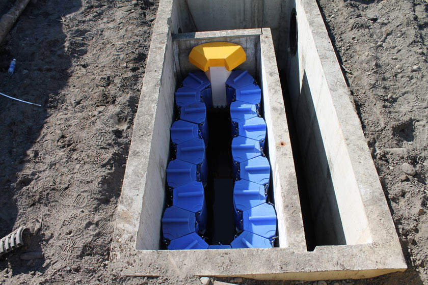
An example of a media filter installation in Philadelphia 4.9.6 Media filter maintenance guidance
All areas of the filter should be inspected regularly and after significant storm events for ponding, sediment and/or debris accumulation, and damage. Corrective measures should be taken when ponding, sediment and/or debris accumulation, and/or damage occurs.
In areas where the potential exists for the discharge and accumulation of toxic pollutants (such as metals), filter media removed from filters must be handled and disposed of in accordance with all City, State, and Federal regulations.
General recommended maintenance activities and frequencies for media filters are summarized in Table 4.9‑1 below.
Table 4.9‑1: Media filter maintenance guidelines
Maintenance activity Frequency Rake filter media surface for the removal of trash and debris from control openings. As needed Repair leaks from the sedimentation chamber or deterioration of structural components. As needed Inspect filter for standing water (filter drainage is not optimal) and discoloration (organics or debris have clogged filter surface). Quarterly Remove the top few inches of filter media and cultivate the surface when filter bed is clogged. Annually Clean out accumulated sediment from filter bed chamber. Annually Clean out accumulated sediment from sedimentation chamber. Sediment and debris buildup may need to be removed by a professional. Consult with a professional, as necessary. Annually Maintain records of all inspections and maintenance activity. Ongoing If the SMP design proposes modifications to the approved saturated hydraulic conductivity of media filters, appropriate modifications should be made to the maintenance schedule (Table 4.9‑1) for the proposed management practice. For example, utilizing an increased filtration rate for sand is appropriate if the maintenance schedule includes increased frequency of sediment removal and replacement of filter media.
The designer is referred to Section 4.10, Pretreatment, Section 4.11, Inlet Controls, Section 4.12, Outlet Controls, and Section 4.13, Landscaping, for information on maintenance guidance for pretreatment, inlet controls, outlet controls, and landscaping.
-
4.10 Pretreatment
4.10.1 Pretreatment introduction
Pretreatment is critical to the design of stormwater management practices (SMPs). Properly designed pretreatment systems help to sustain required stormwater management function, extend service life, and reduce maintenance costs of SMPs. The primary goal of most pretreatment systems is to capture sediment, trash, and debris. This can be done using a variety of methods but is most commonly achieved by decreasing peak stormwater velocities to allow sediment to settle or by filtering incoming stormwater through vegetation to remove sediment before it reaches a downstream SMP.
Pretreatment of runoff from all inlets is required. For all SMPs, the use of sumps and traps or hoods for inlets, and sump boxes with traps or hoods downstream of trench drains, is the minimum requirement. The designer is referred to Section 4.11, Inlet Controls, for guidance on inlets. Pretreatment beyond these minimum requirements is recommended for SMPs with catchment areas that generate high sediment loads, such as roadways and parking lots and may be required for sites that generate pollutants such as loading docks, material storage facilities, junk yards, and waste collection and disposal sites. The designer should reference the pretreatment sections within the individual SMP Sections of Chapter 4 for SMP‑specific guidance regarding pretreatment.
In the following section, guidance is provided on three of the most commonly applied pretreatment practices. These consist of:
- Filter strips
- Forebays
- Swales
The design of an effective pretreatment system may incorporate any number of these or other types of pretreatment systems, and the designer should not be limited by the guidance provided in this Manual. Successful pretreatment systems will combine appropriate materials and designs specific to each site.
Table 4.10‑1 below provides guidance on the typical applicability of the types of pretreatment systems covered in this section. Red indicates that the pretreatment type would typically be used with the SMP; yellow indicates that the pretreatment type may be used with the SMP in certain circumstances; and blue indicates that the pretreatment type would not typically be used with the associated SMP. Filter strips are typically applicable for diffuse stormwater flow, while forebays and swales are typically applicable for concentrated stormwater flow.
The pretreatment systems within this section are not typically applicable for green roofs, blue roofs, and cisterns treating roof runoff. The designer is referred to the pretreatment sections within Section 4.5, for cistern pretreatment guidance.
Table 4.10‑1: Pretreatment applicability guidance
SMP Pretreatment for diffuse flow Pretreatment for concentrated flow Filter strips Forebays Swales Bioinfiltration/bioretention Typical Typical Typical Ponds and wet basins Typical Typical Typical Subsurface infiltration Occasional Occasional Occasional Drainage wells Occasional Occasional Occasional Subsurface detention Occasional Occasional Occasional Media filters Occasional Occasional Occasional Porous surfaces Atypical Atypical Atypical Green roofs Atypical Atypical Atypical Blue‑green roofs Atypical Atypical Atypical Cisterns Atypical Atypical Atypical Blue roofs Atypical Atypical Atypical 4.10.2 Filter strips
Filter strips consist of densely vegetated land or gravel covered areas, as seen in the photo below, that treats stormwater sheet flow from adjacent pervious and impervious areas. These systems function by reducing runoff velocity, trapping sediment and pollutants, and, in some cases, infiltrating a portion of the runoff into the ground. Filter strips are generally a sensible and cost-effective stormwater pretreatment option applicable to a variety of development sites, including roads and highways.
Design of filter strip SMPs is not limited to the examples shown within this text. Successful stormwater management plans will combine appropriate materials and designs specific to each site.
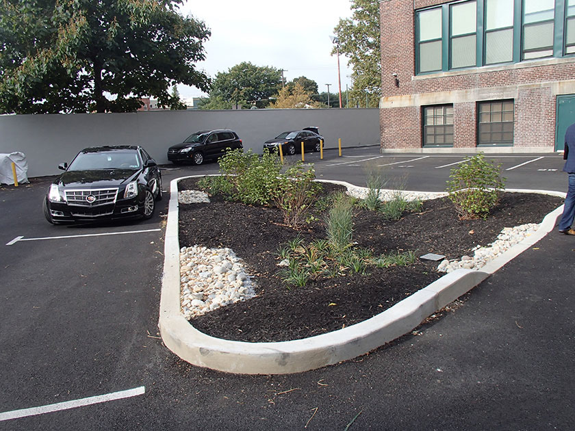
An example of filter strips in Philadelphia When can filter strips be used?
Filter strips are a pretreatment option typically applicable to bioinfiltration/bioretention basins and ponds and wet basins. Depending on the site layout and stormwater conveyance design, they may be applicable to subsurface infiltration, subsurface detention, and media filters.
Filter strips are typically used for pretreatment of diffuse sheet flow. They are a pretreatment option for SMPs in residential, commercial, and light industrial developments, and for roads, highways, and parking lots.
Key advantages of filter strips
- Relatively simple structures that provide effective runoff pretreatment
- Effective at slowing runoff velocities, removing pollutant loads, and promoting infiltration of runoff produced by both impervious and pervious areas
- Extend the life of associated SMPs and decrease their hydraulic residence time
- Decrease the frequency of required maintenance of associated SMPs
Key limitations of filter strips
- Require preservation and minimization of impacts leading to compaction and/or erosion
- Often require medium-to-large vegetated areas, making them often impractical in an ultra-urban setting
Key design considerations for filter strips
- Filter strip effectiveness may be enhanced by installing berms and retentive grading perpendicular to the flow path. A pervious berm and/or retentive grading allows for a reduction in both runoff velocity and volume, thus improving pollutant removal capabilities by providing a temporary (very shallow) ponded area.
- The use of existing vegetated areas that have surface features that disperse runoff is encouraged, as the use of these areas will also reduce overall site disturbance and soil compaction.
- Trees and shrubs may be allowed in the flow path if the filter strip exceeds the minimum length and width requirements specified in Table 4.10‑2 below.
- The vegetation for filter strips may be comprised of turf grasses, meadow grasses, shrubs, and native vegetation (Appendix I houses plant lists). Approved native grass mixes are preferable. Seed shall be applied at the rates specified by the supplier.
- Turf grass is generally not recommended but may be acceptable provided the designer can show it meets all requirements.
- A pea gravel diaphragm, which is a gravel-filled trench running along the top of the filter strip’s slope, may be used as a pretreatment level spreader, maintaining sheet flow into the filter strip.
- Vegetation cover should be maintained at 85%. If vegetation is damaged, the damaged areas should be re-established in accordance with the original specifications or according to a new design approved by the Philadelphia Water Department (PWD). In all design cases where vegetation is to be established, the planting regime should be as dense as the soil conditions can sustain. This is especially true at the top portions of the filter strip where the highest sheet flow velocities are found. Soils that can sustain higher quantities and qualities of vegetation may need to be added to ensure the thick vegetative densities needed for sustainable filter strip performance. All vegetation deficiencies should be addressed without the use of fertilizers or pesticides, if possible.
Filter strip design and material standards
- It is critical that plant materials are appropriate for soil, hydrologic, light, and other site conditions. The designer is referred to the list of native species in Appendix I for plant lists. Ponding depth, drain down time, sunlight, salt tolerance, soil infiltration capacities, pollution tolerances, root structure, and other conditions must be taken into consideration when selecting plants.
- Concentrated flow can have an erosive effect that can damage the filter strip, rendering the strip ineffective. If discharge of concentrated flow to the filter strip is proposed, level spreading devices are required to provide uniform sheet flow. The designer is referred to Section 4.12, Outlet Controls, for guidance on level spreaders.
- Filter strips may not be used in high-use areas unless precautions are taken to minimize disturbance of the filter strip, such as signage, fences, and placement of sidewalks or paths to minimize pedestrian or vehicular traffic.
- The maximum allowable flow path to a filter strip, without the installation of energy dissipaters and/or flow spreaders, is 75 feet for impervious ground cover and 150 feet for pervious ground cover.
- The maximum contributing drainage area must be less than five acres and must not exceed a drainage area to filter strip area ratio of 6:1.
- The maximum contributing drainage area slope must be less than 5%, unless energy dissipation and/or flow spreaders are provided up-gradient of the filter strip.
- The filter strip slope must not exceed 8%. Slopes less than 5% are generally preferred. Filter strips with slopes that exceed 5% should implement check dams to encourage ponding and prevent scour and erosion of the filter strip area. The designer is referred to Section 4.10.4, Swales, for additional guidance on check dam design.
- The slope (parallel to the flow path) of the top of the filter strip, after a flow spreading device, must be very small (less than 1%) and gradually increase to the designed value to protect from erosion and undermining of the device.
- Plants must be established at the time of filter strip completion (at least three months after seeding). No runoff must be allowed to flow across the filter strip until the vegetation is established.
- Filter strip length must be in accordance with Table 4.10‑2 below.
Table 4.10‑2: Required starting design values for filter strip length
Required starting design values for filter strip length Strip length perpendicular to flow path Largest feasible on-site Strip length parallel to flow path Four feet* to 150 feet * The minimum pretreatment filter strip value is based on the length of the receiving flow path. Figure 4.10‑1 below shows how the minimum length requirement changes as both flow path and filter strip slope change. - For contributing flow paths less than 30 feet in length, Figure 4.10‑1 below must be used to determine the filter strip length. The filter strip length requirements reflected in Figure 4.10‑1 are scaled from dimensions of a grassy vegetative swale for the same slope and flow conditions mentioned in Table 4.10‑2.
Figure 4.10‑1: Design specifications for narrow pretreatment filter strips with flow paths less than 30 feet in length
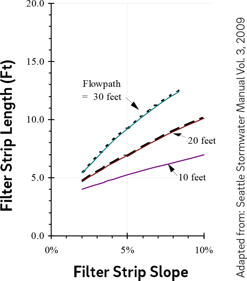
- For contributing flow paths greater than 30 feet in length, the required flow characteristics for maximum velocity and depth listed in Table 4.10‑3 below must be used.
Table 4.10‑3: Maximum velocities and water depths for filter strip area
Maximum velocities and water depths for filter strip area Maximum velocity 1 ft/s max., less than 0.5 ft/s preferred Maximum water depth 1 inch max., less than 0.5 inch preferred The values for both maximum velocity and water depth were taken from US DOT Stormwater Best Management Practices in an Ultra-Urban Setting: Selection and Monitoring and the Seattle BMP Manual. Filter strip construction guidance
Guidance on typical construction sequencing to ensure proper installation and performance of filter strips is as follows:
- Areas for filter strips must be clearly marked before any site work begins to avoid soil disturbance and compaction during construction.
- In areas where soil is compacted, tilling to depths of 12 to 18 inches is necessary. A minimum of six inches of topsoil must be added into the tilled soil column, and small trees and shrubs with capabilities for deep root penetrations should be introduced to maximize the infiltrative capacity of the soil.
- Provide erosion and sedimentation control protection on the site such that construction runoff is directed away from the proposed filter strip location.
- Complete site elevation and retentive grading, if proposed. Stabilize the soil disturbed within the limit of earth disturbance.
- Install energy dissipaters and flow spreaders if required. The designer is referred to Section 4.12, Outlet Controls, for more detailed construction information.
- Construct filter strip as specified in the design.
- Seed and plant vegetation (plants, shrubs, and trees) as indicated on the plans and specifications.
- Once site vegetation is stabilized, remove erosion and sediment control protection.
Filter strip maintenance guidance
All areas of the filter strip should be inspected after significant storm events for ponding. Corrective measures should be taken when excessive ponding occurs.
General recommended maintenance activities for filter strips are summarized in Table 4.10‑4.
Table 4.10‑4: Filter strip maintenance guidelines
Early maintenance activity Frequency Inspect erosion control and flow spreading devices until soil settlement and vegetative establishment of contributing areas has occurred. Biweekly Water vegetation at the end of each day for two weeks after planting is completed. Daily for two weeks after installation Water vegetation regularly to ensure successful establishment after planting. Every four days during periods of four or more days without rain, June through August for the 24 months after installation Inspect vegetation for signs of disease or distress. Treat or replace, as necessary. Biweekly for the first year after installation Ongoing maintenance activity Frequency Mow and/or trim vegetation (not applicable to all filter strips). Filter strips that need mowing are to be cut to a height no less than four inches. Greater than five inches is preferred. As needed Inspect all vegetated strip components expected to receive and/or trap debris and sediment for clogging, excessive debris, and sediment accumulation; remove sediment during dry periods. Quarterly Inspect vegetated areas for erosion, scour, and unwanted growth. This should be removed with minimum disruption to the planting soil bed and remaining vegetation. Semiannually Inspect all level spreading devices for trapped sediment and flow spreading abilities. Remove sediment and correct grading and flow channels during dry periods. Semiannually Maintain records of all inspections and maintenance activity. Ongoing When correcting grading of a flow spreading device, proper erosion and sediment control precautions should be used in the concentrated area of disturbance to ensure protection of the remaining portion of the filter.
Disturbance to filter strips should be minimal during maintenance. At no time should any vehicle be driven on the filter strip. In addition, foot traffic should be kept to a minimum.
If the filter strip is of the type that needs mowing, such as turf grass and possibly other native grasses, push mowers, not riding mowers, should be used. The filter strip should be mowed perpendicular to the flow path (however not exactly the same path every mowing) to prevent any erosion and scour due to channeling of flow in the maintenance depressions.
Filter strips are often used as a convenient area for snow storage. Therefore, filter strip vegetation should be salt-tolerant, and the project’s SMP Maintenance Schedule Forms should include removal of sand build-up at the toes of the filter strip slope. If the filter strip cannot provide pretreatment in the winter due to snow storage or vegetation choice, another pretreatment should be provided.
4.10.3 Forebays
A forebay is a small impoundment designed to dissipate the energy of incoming runoff and allow for initial settling of coarse sediments. They are typically used for pretreatment of runoff prior to discharge into an SMP. Storage created within forebay systems is primarily intended to promote gross pollutant removal prior to introducing flow into a downstream water quality SMP. The forebay is typically isolated from the downstream SMP facility by an earthen, stone, or concrete berm which creates the outer limitations of the forebay.
In some cases, forebays may be constructed as separate structures, but often they are integrated into the design of larger SMPs. Since forebays are typically designed as surface features, surface forebays are the primary focus of this section. Storm drain piping or other conveyance practices may be aligned upstream of a forebay to discharge into one, or several, forebays, as appropriate for the particular site.
Design of forebays is not limited to the examples shown within this text. Successful stormwater management plans will combine appropriate materials and designs specific to each site.
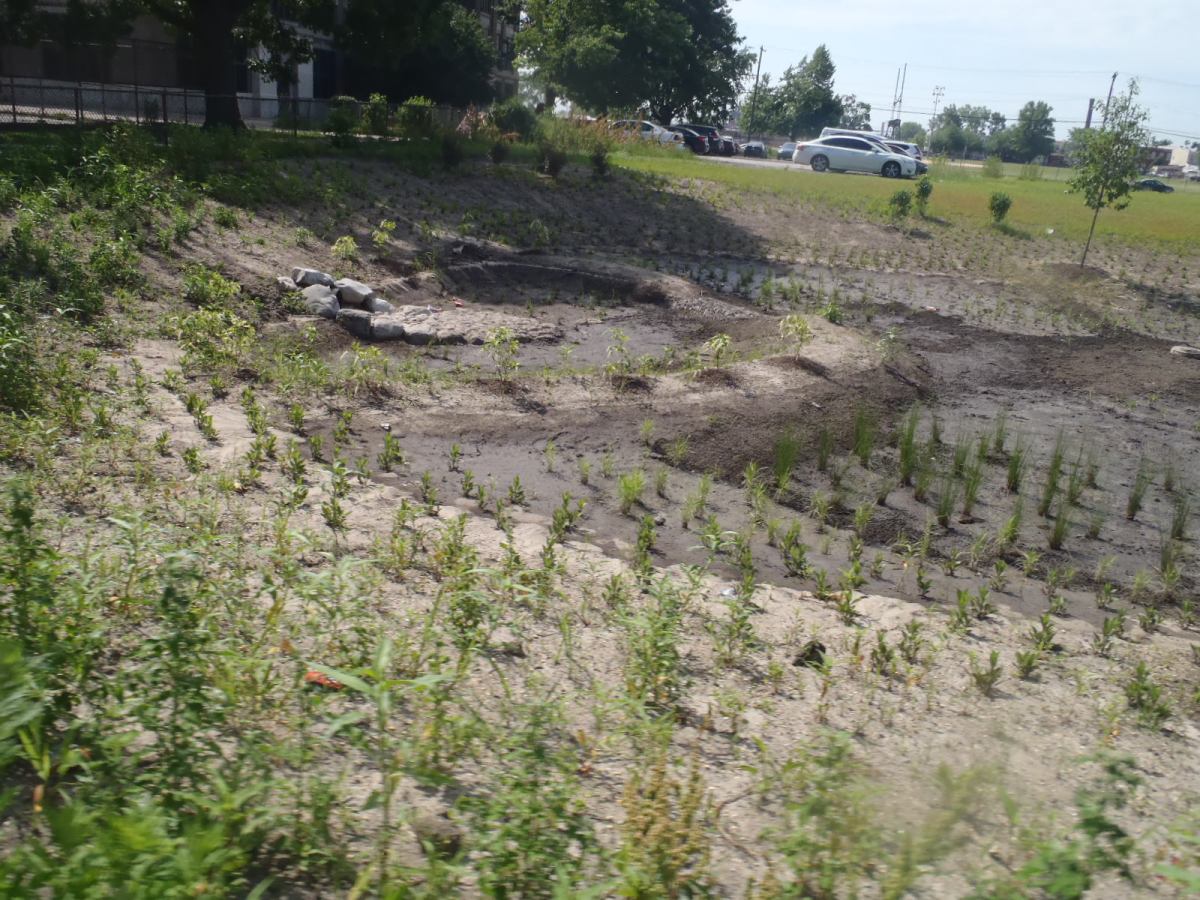
An example of a forebay in Philadelphia When can forebays be used?
Forebays are a pretreatment option typically implemented with bioinfiltration/bioretention basins and ponds and wet basins. Depending on the site layout and stormwater conveyance design, they may be applicable to subsurface infiltration, subsurface detention, and media filters. Forebays are typically used for pretreatment at points of concentrated stormwater flow.
Key advantages of forebays
- Very effective at removing coarse sediment and debris from small frequent storm events
- Reduce the frequency of maintenance of the associated SMP
- Enhance pollutant removal capabilities of the associated SMP
Key limitations of forebays
- Take up space and expand the footprint of the associated SMP
- Generally ineffective at fine particulate removal
- Increase construction costs and required land area
- Require careful monitoring and removal of accumulated sediment, which can be visible and create aesthetic concerns
Key design considerations for forebays
- A berm placed on the downslope side of a mild slope can be used to create a forebay without additional excavation.
- As an alternative to an earthen basin, an underground structure may serve as a forebay; however, use of fully enclosed structures must allow accessibility for inspection and maintenance.
- Forebay systems can be vegetated or may be lined with hard materials such as rock or concrete. Vegetation within forebays can help to improve aesthetics and assist with pollutant removal; however, high velocities and high rates of sedimentation within forebays can make vegetation survival difficult.
- Forebays should be installed in locations that are accessible by maintenance equipment and should be designed for ease of maintenance. Those constructed with a bottom made of concrete or other solid materials make sediment removal easier and more accessible by heavy machinery.
- Forebay sizing should consider expected level of sediment loading. Drainage area size and characteristics have an impact on the nature and frequency of maintenance activities and corresponding long-term performance. For example, large parking lots deliver more sediment to an SMP than roof areas and therefore require additional maintenance than systems that receive only roof runoff.
- Exposed earthen slopes and the bottom of the forebay should be stabilized using seed mixes appropriate for soils, mowing practices, and exposure to inundation.
- If the forebay is separated from the downstream SMP by an impervious barrier such as a concrete wall or weir, an outlet control structure may be required to drain the forebay. A designed overflow spillway section may be constructed on the top of the berm separating the forebay from the SMP to allow overflow to exit the forebay and enter the downstream SMP at non-erosive velocities.
Forebay design and material standards
- Forebays within large SMPs, such as ponds and wet basins, must contain 10% to 15% of the total permanent pool volume of the larger SMP.
- For forebays within smaller SMPs such as bioinfiltration/bioretention basins, the storage volume should be sized to retain 0.25 inches of runoff of contributing directly connected impervious area (DCIA), with an absolute minimum of 0.1 inch of runoff.
- A stone berm must physically separate the forebay from its associated SMP. The berm should span the entire width of the basin.
- Inlet controls for forebays must include riprap aprons, stone placed in concrete, or some other type of energy dissipation device to rapidly reduce the inflow velocity for erosion/scour protection and to encourage settlement of suspended solids. The designer is referred to Section 4.11, Inlet Controls, for information on design requirements for inlet control systems.
- Permanent vertical markers constructed of durable materials must be installed within the forebay area to indicate the sediment depth.
- Inspection and maintenance access must be provided to allow for periodic sediment removal; this is most commonly provided via stabilized and mildly sloping graded areas that can be accessed by heavy equipment.
- Exit velocities from the forebay must be non-erosive. The designer is referred to the latest edition of the Pennsylvania Department of Environmental Protection (PA DEP) Erosion and Sediment Pollution Control Program Manual for information on design standards for erosion and sedimentation control practices.
Forebay construction guidance
Guidance on typical construction sequencing to ensure proper installation and performance of forebays is as follows:
- Install all temporary erosion and sedimentation controls. The area immediately adjacent to the forebay must be stabilized in accordance with the latest edition of the PA DEP Erosion and Sediment Pollution Control Program Manual prior to SMP construction.
- Prepare site for excavation and/or embankment construction.
- All existing vegetation should remain, if feasible, and must only be removed if necessary for construction.
- If excavation is required, clear the area to be excavated of all vegetation. Remove all tree roots, rocks, and boulders only in excavation area.
- Excavate bottom of forebay to desired elevation (if necessary).
- Install surrounding embankments and inlet and outlet control structures.
- Grade subsoil in bottom of forebay and compact surrounding embankment areas and around inlet and outlet structures.
- Apply and grade planting soil.
- Seed, plant, and mulch according to Planting Plan.
Forebay maintenance guidance
All areas of the forebay should be inspected after significant storm events. Corrective measures must be taken if erosion or excessive debris accumulation occurs. General recommended maintenance activities for forebays are summarized in Table 4.10‑5.
Table 4.10‑5: Forebay maintenance guidelines
Ongoing maintenance activity Frequency Remove trash and debris. As needed Weed by hand and remove invasive plants. As needed Grassed areas require periodic prudent fertilizing, de-thatching, and soil conditioning. As needed Trees, shrubs, and other vegetative cover will require periodic maintenance such as fertilizing, pruning, and pest control. As needed Mow/trim forebay vegetation. As needed Dredge sediment. Accumulated sediment must not occupy greater than 50% of the forebay volume. As needed, but at least once every five years* Inspect forebay for potential problems including subsidence, erosion, cracking, or tree growth on the stabilized overflow spillway embankment; damage to the spillway; sediment accumulation; changes in the condition of the inflow; and erosion within the forebay and banks. Annually Maintain records of all inspections and maintenance activity. Ongoing * The frequency of sediment removal depends on site conditions such as soil type and maintenance of site stabilization which influence the sediment load on the basin. In most cases, no specific limitations have been placed on disposal of sediments removed from forebays. Studies to date indicate that sediments are likely to meet toxicity limits and can be safely landfilled. It is the owner’s responsibility to ensure that the sediment is not contaminated. On-site sediment disposal is always preferable as long as the sediments are deposited away from the edge of the forebay to prevent their re-entry, and away from recreation areas where people could inhale resulting dust. Information regarding sediment disposal should be provided to the property owner by the design professional.
Sediments should be tested for toxicants in compliance with current disposal requirements if land uses in the drainage area are commercial or industrial, or if indications of pollution are seen or smelled.
4.10.4 Swales
A swale is an open channel vegetated with a combination of grasses and other herbaceous plants, shrubs, and/or trees that can reduce peak flow at the discharge point by increasing travel time and friction along the flow path. A traditional swale typically provides conveyance and pretreatment to another SMP, such as a bioinfiltration/bioretention basin, and provides some infiltration and water quality benefits. Check dams can increase these functions by providing ponding areas where settling and infiltration can occur. As the number of check dams increases, a swale may resemble a series of bioinfiltration/bioretention basins while still being designed to convey peak flows. Swales planted with turf grass provide some of these functions, but turf grass is not as effective as deeper-rooted vegetation at decreasing peak flow rates, allowing infiltration, and controlling erosion. A swale can be more aesthetically pleasing than a concrete or rock-lined drainage system and is generally less expensive to construct. Runoff can enter the swale through a curb opening, pipe, weir, or other design, and it may flow off of a curbless parking lot or road and down a swale slope in a diffuse manner.
When not used for conveyance and/or pretreatment, swales may be considered narrow bioinfiltration/bioretention basins, if designed as such. This section only covers the design of swales as pretreatment systems; the designer is referred to Section 4.1, Bioinfiltration/bioretention, for guidance on swales designed for Water Quality treatment.
Design of swales is not limited to the examples shown within this text. Successful stormwater management plans will combine appropriate materials and designs specific to each site.
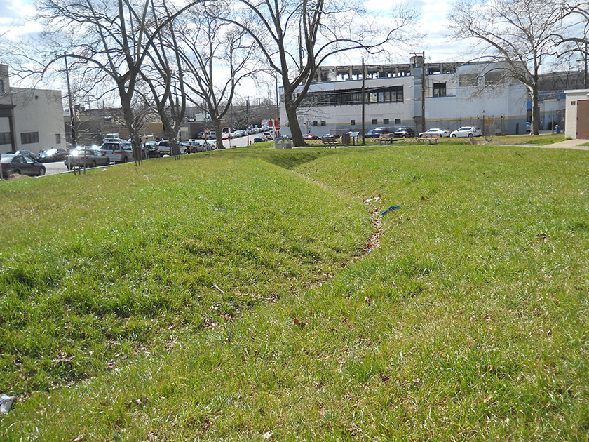
An example of a swale in Philadelphia When can swales be used?
Swales are pretreatment options typically applicable to bioinfiltration/bioretention basins and ponds and wet basins. Depending on the site layout and stormwater conveyance design, they may be applicable to subsurface infiltration, subsurface detention, and media filters.
Swales are typically used for pretreatment and/or conveyance of concentrated stormwater flow. They may be applicable in many urban settings, including parking lots, commercial and light industrial facilities, and roads and highways (via median strips and shoulders). Swales can also be used in residential developments and constructed, with approved property agreements, parallel to the sidewalks and streets. Alternatively, they can collect stormwater from multiple properties and convey it to a shared SMP.
Key advantages of swales
- Allow for flexible design for both stormwater treatment and conveyance
- Can often be used in lieu of more expensive subsurface conveyance or rock-lined/concrete channels
- Can effectively balance storage, treatment, and infiltration with peak flow conveyance needs
- Can be designed to fit into many types of landscapes in an aesthetically pleasing manner
- Can effectively balance needs for infiltration and treatment during small storms with needs for conveyance during large storms
Key limitations of swales
- Generally distributed across a larger area than other SMPs
- May have limited opportunities for implementation due to the amount of open space available at the site
Key design considerations for swales
- The first ponding area may be designed as a sediment forebay and function as a pretreatment practice for the remainder of the swale or downstream SMPs. Vegetated or stone filter strips are also options for pretreatment.
- The excavated channel itself provides the storage volume and conveyance capacity of the swale. An effective swale design will balance the need for infiltration and treatment during small storms with need for conveyance during large storms.
- The site’s natural topography should be considered when siting the swale; if possible, the swale should be located along contours and natural drainage pathways with slopes of 2% to 3%.
- A bottom channel width of two to eight feet is recommended.
- The soil provides a growing medium for plants and allows for infiltration. The growing medium may consist of amended in situ soils or imported soil.
- A crushed stone layer may be added beneath the soil to increase storage and promote infiltration. Stone will perform this function most effectively when placed beneath ponded areas.
- In some cases, an underdrain and piping system may be designed to prevent prolonged ponding of stormwater or to collect and convey water to another facility such as an infiltration trench. Underdrain systems may be appropriate in locations where conditions are not ideal for infiltration. The designer is referred to Section 3.3 for detail on minimum infiltration rates and infiltration testing requirements.
- Vegetation or ground cover within a swale should be suitable for expected velocities. For the swale flow path, native grass mixes are preferable. Native wildflowers, grasses, and ground covers, which can be designed to require mowing only once or twice annually, are preferred to turf and lawn areas.
- It is recommended that swale SMP designs include check dams. Ponding behind check dams provides storage, increases infiltration, increases travel time, reduces peak flows, and helps prevent erosion by dissipating energy.
- Check dams can be constructed from concrete, stone, boulders, earth, or other materials.
- If a stone check dam is designed to be overtopped, appropriate selection of aggregate will ensure stability during flooding events. In general, one stone size for a dam is recommended for ease of construction. However, two or more stone sizes may be used, provided a larger stone (e.g., R-4) is placed on the downstream side, since flows are concentrated at the exit channel of the weir. Several feet of smaller stone (e.g., American Association of State Highway and Transportation Officials #57) can then be placed on the upstream side. Smaller stone may also be more appropriate at the base of the dam for constructability purposes.
- Check dams should be evenly spaced and at least six inches high.
Swale design and material standards
- If a swale is being designed as a primary SMP, it must meet the applicable design requirements for bioinfiltration/bioretention basins, as well as the applicable requirements in this section. The designer is referred to Section 4.1, Bioinfiltration/bioretention, for guidance and design requirements.
- Swales must convey the ten‑year, 24‑hour storm with a minimum of six inches of freeboard and a maximum depth of 18 inches. Flow over check dams may be estimated using a weir equation.
- Swales must be designed to resist erosion. It is recommended that the swale convey the two‑year, 24‑hour storm without erosion. The latest edition of the PA DEP Erosion and Sediment Pollution Control Program Manual is recommended as a reference for these calculations. Soil mix, vegetation, and temporary or permanent stabilization measures must be adjusted as needed.
- Plants must be established at the time of swale completion (at least three months after seeding).
- Energy dissipaters must be evaluated for use at points of concentrated inflow. The designer is referred to Section 4.11, Inlet Controls, for information on the design of energy dissipaters.
- It is critical that plant materials are appropriate for soil, hydrologic, light, and other site conditions. The designer is referred to the list of native species in Appendix I for plant lists. Ponding depth, drain down time, sunlight, salt tolerance, and other conditions must be taken into consideration when selecting plants. Turf grass is generally not recommended but may be acceptable provided the designer can show it meets all requirements.
- Maximum side slopes for parabolic channel swales are as follows:
- All – 2(H):1(V) (The recommended side slope is 3(H):1(V))
- Mowed – 4(H):1(V) to avoid “scalping” by mower blades
- Check dams intended to provide ponding in swale SMP designs must not be porous (i.e. composed of stone gabions), as water should be ponded behind each check dam and forced to infiltrate. If the swales are only being used for conveyance or to increase time of concentration, check dams may be porous.
Swale construction guidance
Guidance on typical construction sequencing to ensure proper installation and performance of swales is as follows:
- To promote infiltration through swales, rock construction entrances must not be located on top of areas of proposed swale bottoms.
- Heavy equipment exclusion zones must be established to avoid compaction of the swale’s bottom footprint during construction.
- Begin vegetated swale construction only when the up-gradient site has been sufficiently stabilized and temporary erosion and sediment control measures are in place. Vegetated swales should be constructed and stabilized very early in the construction schedule, preferably before mass earthwork and paving increase the rate and volume of runoff. The designer is referred to the latest edition of the PA DEP Erosion and Sediment Pollution Control Program Manual for information on design standards for erosion and sedimentation control practices.
- Rough grade the swale. Equipment must avoid excessive compaction and/or land disturbance. Excavating equipment should operate from the side of the swale and never on the bottom. If excavation leads to substantial compaction of the subgrade (where an infiltration trench is not proposed), 18 inches must be removed and replaced with a blend of topsoil and sand to promote infiltration and biological growth. At the very least, topsoil must be rototilled into the subgrade in order to penetrate the compacted zone and promote aeration and the formation of macropores. Following this, the area should be disked prior to final grading of topsoil.
- Construct check dams, if required.
- Fine grade the swale. Accurate grading is crucial for swales. Even the smallest non-conformities may compromise flow conditions.
- Seed and vegetate according to final planting plans. Seeding with an annual turf grass is recommended to provide temporary stabilization. Plant the swale at a time of the year when successful establishment without irrigation is most likely. Provide temporary irrigation during any periods of little rain or drought. Vegetation should be established as soon as possible to prevent erosion and scour.
- Concurrent with the previous step, stabilize freshly seeded swales with appropriate temporary or permanent soil stabilization methods, such as erosion control matting or blankets. If runoff velocities are high, consider sodding the swale or diverting runoff until vegetation is fully established. Erosion and sediment control methods must adhere to latest edition of the PA DEP Erosion and Sediment Pollution Control Program Manual.
- Once the swale is sufficiently stabilized, remove temporary erosion and sediment controls. It is very important that the swale be stabilized before receiving stormwater flow. No runoff must be allowed to flow in the swale until grass is established.
Swale maintenance guidance
Swales should be inspected after significant storm events, and corrective measures should be taken if erosion or excessive debris accumulation occurs. General recommended maintenance activities for swales are summarized in Table 4.10‑6.
Table 4.10‑6: Swale maintenance guidelines
Ongoing activity Frequency Treat or replace diseased trees and shrubs. As needed Inspect soil and repair eroded areas. Monthly Remove litter and debris. Monthly Clear leaves and debris from overflow. Monthly Replace filter bags for pretreatment devices. Ensure filter bag is installed properly. Quarterly Inspect trees and shrubs to evaluate health. Semiannually Prune trees and shrubs. Annually Inspect for sediment build-up, erosion, vegetative conditions, etc. Annually Inspect outlet control devices after several storms to ensure that they are functioning properly and that there are no erosion problems developing. Ongoing Maintain records of all inspections and maintenance activity. Ongoing -
4.11 Inlet Controls
4.11.1 Inlet control introduction
Inlet controls are the structures or landscape features that manage the runoff flow into a stormwater management practice (SMP). Distribution piping, flow splitters, curbless design, curb openings, energy dissipaters, and inlets are all examples and elements of inlet controls. Inlet controls often serve an integral role in the pretreatment of stormwater entering an SMP by minimizing erosion potential or capturing sediment and gross solids. They restrict the volume and rate of flow introduced to an SMP while ensuring that flow is delivered to the SMP without causing erosion.
Design of inlet controls is not limited to the examples shown within this text. Successful stormwater management plans will combine appropriate materials and designs specific to each site.
Table 4.11‑1 below is a guide to the inlet controls covered in this section, showing whether they are typically used in conjunction with various SMP practices. Red indicates that an inlet control would typically be used with an SMP; yellow indicates that the inlet control may be used with the associated SMP in certain circumstances; and blue indicates that the inlet control would not typically be used with the associated SMP. An appropriate inlet control must be matched to the contributing drainage area and receiving SMP.
Table 4.11‑1: Inlet controls applicability guidance
SMP Flow splitters Curbless design / curb openings Energy dissipaters Inlets Bioinfiltration/ bioretention Typical Typical Typical Typical Ponds and wet basins Typical Typical Typical Typical Subsurface infiltration Typical Atypical Atypical Typical Drainage wells Typical Atypical Atypical Typical Cisterns Typical Atypical Atypical Occasional Subsurface detention Typical Atypical Atypical Typical Media filters Occasional Occasional Occasional Occasional Porous surfaces Atypical Atypical Atypical Atypical Green roofs Atypical Atypical Atypical Atypical Blue‑green roofs Atypical Atypical Atypical Atypical Blue roofs Atypical Atypical Atypical Atypical 4.11.2 Flow splitters
Flow splitting devices are used to direct a fraction of runoff into an SMP while bypassing excess flows from larger events around the SMP into a bypass pipe or channel. The bypass typically connects to another SMP or to a receiving drainage system, depending on the design and management requirements. This type of inlet control can also serve as the positive overflow for the SMP.
Flow splitters can be constructed by installing bypass weirs in stormwater control structures such as inlets and manholes. On a larger scale, they can be constructed using concrete baffles in manholes.
When can flow splitters be used?
Flow splitters are inlet controls that are typically applicable to bioinfiltration/bioretention basins, subsurface infiltration and detention SMPs, ponds and wet basins, and cisterns. Depending on the site layout and stormwater conveyance design, they may be applicable to media filters.
Flow splitters are used to divert required Water Quality Volume (WQv) to appropriate SMPs while allowing excess stormwater to pass to another SMP, storm sewer, or receiving water body. They may also be used to divert first flush stormwater to lower-maintenance surface SMPs while allowing excess flows to discharge to subsurface SMPs.
Key advantages of flow splitters
- Divide runoff volume and divert it to different destinations to alleviate downstream flooding during a storm or to prevent a SMP from exceeding its designed capacity
- Reduce the cost of building an SMP by reducing the storage capacity needed to provide positive overflow
- Enhance SMP longevity by reducing the volume of runoff treatment and the amount of erosion, slope, and vegetation damage
- Separate the first flush volume, which contains most of the runoff pollutants, allowing it to be sent to more intensive treatment SMPs or be treated for a longer period without being diluted by additional runoff, which can be diverted downstream or to another SMP
Key limitations of flow splitters
- Have the potential to cause flow reversal under certain circumstances (e.g., due to lack of backflow preventer or one-way valve) in which water will flow from an SMP back through the flow splitter
Key design considerations for flow splitters
- Flow splitters can be used as part of a connected system of SMPs to meet the Philadelphia Water Department (PWD) Stormwater Regulations (Stormwater Regulations). For example, a flow splitter can be used to divert portions of larger storm events from Water Quality requirement-meeting SMPs to SMPs better-suited to meet the Flood Control requirement.
- There are two basic considerations in the design of flow splitters: the elevation of the bypass weir and the capacity of the pipe to and from the SMP, which controls the maximum flow the SMP can receive and discharge.
Figure 4.11‑1: Flow splitter with typical features
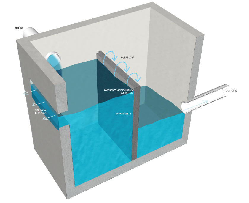
Flow splitter design and material standards
- The elevation of the bypass weir dictates the maximum elevation of the water in the SMP. The bypass elevation must be set at minimum, at the design storage elevation in the SMP. Flow will then only start to bypass the SMP once it exceeds the design storage elevation of the SMP. The design storage elevation is the water surface elevation at which the SMP storage area contains the runoff volume from a design storm event (for example, the WQv or the ten‑year, 24‑hour storm).
- Positive overflow must be provided for large storm events, up to and including the 100‑year, 24‑hour storm, or, if the project is exempt from Flood Control, the ten‑year, 24‑hour storm. Overflow structures and pipes must be designed to convey at least the ten‑year, 24‑hour storm. The system should have enough capacity to transmit larger flows over the bypass weir without surcharging the structure.
- Flow splitters must be designed with appropriate materials, taking flow velocities and exposure to the elements into consideration. Flow splitters are typically constructed from reinforced concrete, galvanized steel, or brick and mortar.
- Flow splitters must be anchored to stormwater control structures using methods and materials appropriate to the structure’s environment, such as corrosion-resistant hardware or epoxy mortar.
4.11.3 Curbless design/curb openings
Curbless designs allow stormwater to flow directly from the impervious source to the SMP. This type of design discourages the concentration of flow and reduces the energy of stormwater entering an SMP. Curbless designs are often used with bioretention basin islands or roadside swales.
Curb openings provide an alternative inlet control when a curbless design or the use of inlet structures is not possible. Bioinfiltration/bioretention and landscaped islands in curbed parking lots or roadways often use curb openings as inlet controls.
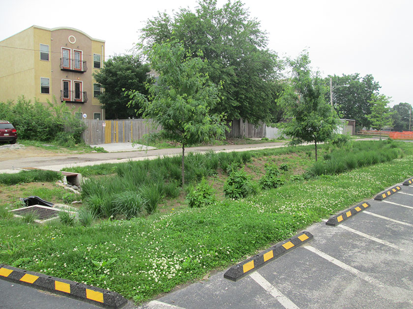
An example of curbless parking lot design in Philadelphia When can curbless design/curb openings be used?
Curbless design/curb openings are inlet controls typically applicable to bioinfiltration/bioretention basins and ponds and wet basins. Depending on the site layout and stormwater conveyance design, they may be applicable to media filters.
Curbless design/curb openings can be implemented in a stormwater management design when standard inlet control and conveyance system structures are neither feasible, due to space or other constraints, nor desired.
Key advantages of curbless design/curb openings
- Can reduce SMP depths and associated excavation and materials costs when chosen in lieu of inlets
- Can be implemented as a strategy to reduce the concentration of stormwater flows into the SMP, thus reducing erosion potential
Key limitations of curbless design/curb openings
- Can result in limited control of bypass flows
- May not be appropriate for subsurface SMPs, large contributing drainage areas, contributing drainage areas with long flow paths over impervious areas, or along driveways or roadways where a sump condition is not feasible
Key design considerations for curbless design/curb openings
- A standard reference for designing traditional drainage systems is U.S. Army Corps of Engineers, Hydraulic Engineering Center Circular 22 (HEC‑22).
- Curb openings should be sized appropriately for sump or on-grade conditions. Further design guidance may be found in the Federal Highway Administration Urban Drainage Design Manual (FHWA-NHI-10-009), Section 4.4.4.2, Curb Opening Inlets.
- Curbless designs should be designed with appropriate non-erosive linings, such as biodegradable erosion control fabric, turf reinforcement mat, stone, or riprap, on all pervious downslope areas to the full width of the curb opening/curbless design. Riprap aprons or riprap basins placed downstream of a flow path are also acceptable, but are considered energy dissipaters, which are discussed in Section 4.11.4.
- Trench drains can be used to convey flow from curb openings across sidewalks.
Figure 4.11‑2: Curb opening with typical features
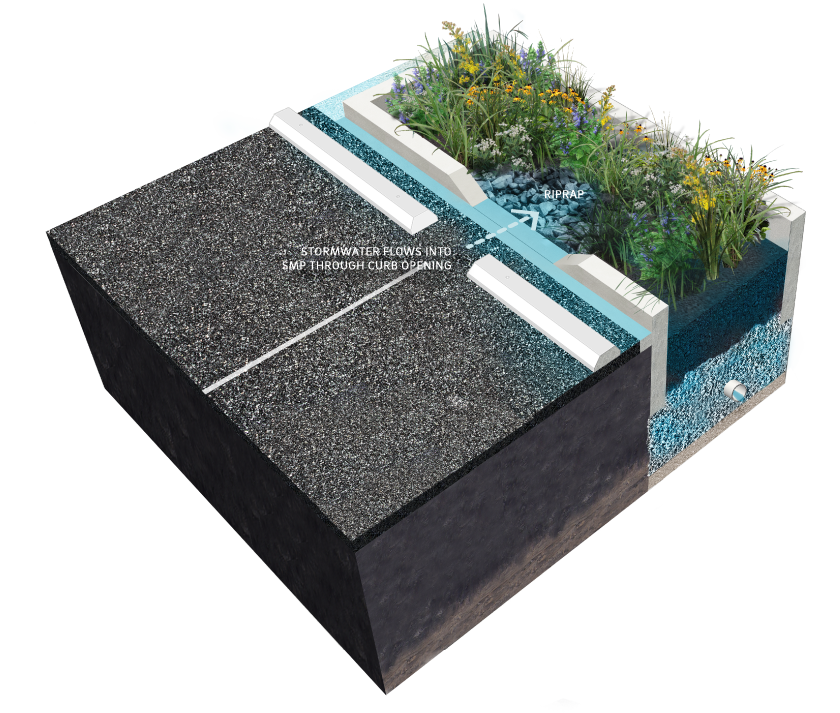
Curbless design/curb opening design and material standards
- If flow is to be introduced through curb openings, the pavement edge must be slightly higher than the elevation of the vegetated areas within the SMP.
- Curbless design/curb openings must be designed to convey flow into an SMP without inducing erosive conditions. Integration of energy dissipaters is recommended where appropriate.
- Curb openings must be designed to reduce bypass of gutter flow past the curb opening. This is a common problem with many curb openings that are oriented perpendicular to flow.
- If curb openings are used to capture runoff, especially from driveways or roadways where the curb openings are not in a sump condition, verification that runoff from the one‑year, 24‑hour storm event will be captured by the curb opening must be provided.
- Roadway materials and thicknesses must be able to withstand the appropriate loads at the edge and prevent undercutting.
- Erosion control fabric must be designed in accordance with the channel design procedures in the latest edition of the Pennsylvania Department of Environmental Protection (PA DEP) Erosion and Sediment Pollution Control Program Manual, or per the manufacturer’s specifications.
- Curb openings are to be designed as gaps in otherwise continuous sections of concrete or granite curb conforming to the specifications of the City of Philadelphia Department of Streets, Standard Construction Items (1997).
- All subsurface portions of concrete or granite curb (i.e. below finished pavement grade) must be continuously installed within the extents of the curb opening.
- Pedestrian fall safety must be considered where the curb openings direct flow adjacent to or beneath sidewalks. The need for edge protection, such as railings or wheel stops, must be evaluated.
- Curb openings must be appropriately sized to convey the design discharge. Curb openings are typically 12 to 48 inches wide. Curb openings must be at least eight inches wide to prevent clogging and for ease of maintenance.
4.11.4 Energy dissipaters
Energy dissipaters are devices or practices designed to reduce the velocity, energy, and turbulence of flow. These structures can be employed when highly erosive velocities are encountered at the end of culverts or at the bottom of steep slopes where aesthetics are not a concern. Energy dissipaters include, but are not limited to, riprap aprons, riprap basins, and baffled outlets.
Riprap aprons are commonly used for energy dissipation due to their relatively low cost and ease of installation. A flat riprap apron can be used to prevent erosion at the transition from a pipe or box culvert outlet to a natural channel. Riprap aprons will provide adequate protection against erosive flows provided there is sufficient length and flare to dissipate energy by expanding the flow.
A riprap outlet basin is a pre-shaped scour hole lined with riprap that functions as an energy dissipater. Like a riprap apron, a riprap basin can be used to prevent erosion at the transition from a pipe or box culvert outlet to an earthen channel.
Baffled outlets are concrete or fiberglass boxes containing an alternating series of baffles and chambers. In addition to reducing flow velocity and energy, baffled outlets can effectively remove sediment, suspended particles, and associated pollutants from stormwater.
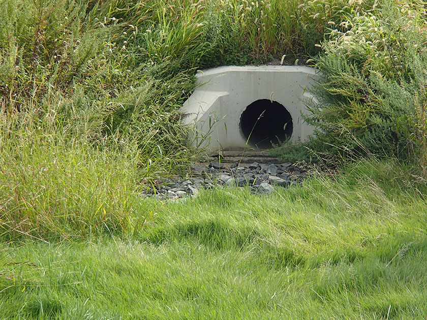
An example of a riprap apron in Philadelphia When can energy dissipaters be used?
Energy dissipaters are inlet controls typically applicable to bioinfiltration/bioretention basins and ponds and wet basins. Depending on the site layout and stormwater conveyance design, they may be applicable to media filters. They can be used downstream of other inlet controls that concentrate stormwater flow, as well as on steeper slopes, to reduce erosion potential.
Key advantages of energy dissipaters
- Reduce velocities of concentrated stormwater runoff
- Reduce erosion potential and allow for more efficient sediment removal efforts, reducing overall maintenance costs and improving SMP performance
- Prevent scour that may undermine the structure discharging concentrated stormwater runoff
- Prevent downslope erosion that may create gullies and scour holes
Key limitations of energy dissipaters
- May increase erosion if not properly designed and installed
- May be difficult to install on some steeply sloping areas and in highly constrained sites
Key design considerations for energy dissipaters
- Select an appropriate energy dissipater type based on site characteristics such as slope, available area, and aesthetics.
- A key design issue is the interface between the end of the energy dissipater and the adjacent downstream area, which is typically vegetated. Vegetation should be well established at this interface. Turf reinforcement mat may be used at this interface to provide additional structure for vegetation.
- Vegetation/plantings can be used to obscure views of energy dissipation structures if aesthetics is a concern.
Figure 4.11‑3: Riprap apron with typical features
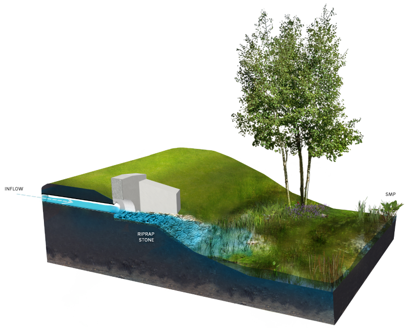
Energy dissipater design and material standards
- Energy dissipaters must be used if flow is concentrated at the entrance to a surface SMP.
- Riprap must be designed and sized in accordance with the riprap apron design procedures in the latest edition of the PA DEP Erosion and Sediment Pollution Control Program Manual or U.S. Army Corps of Engineers, Hydraulic Engineering Center Circular 14 (HEC‑14). The designer is referred to HEC‑14 for the design of alternate types of energy dissipaters, such as drop structures and stilling basins.
- Riprap stone must be angular, graded stone aggregate meeting the specifications of PennDOT Publication 408, Section 703.2, Coarse Aggregate, Type A.
- For stream outfalls, the energy dissipation design tools HEC 11, HEC 14, and HEC 15 must be used for riprap, energy dissipaters, and flexible linings, respectively.
Energy dissipater maintenance guidance
All areas of the energy dissipater should be inspected after significant storm events for ponding. Corrective measures should be taken when excessive ponding occurs.
General recommended maintenance activities for energy dissipater are summarized in Table 4.11‑2.
Table 4.11‑2: Energy dissipater maintenance guidelines
Ongoing maintenance activity Frequency Inspect energy dissipaters after storms for displaced stones, slumping, and erosion at edges, particularly downstream or downslope. Repair or replace damaged riprap. Monthly/concurrent with storm events Inspect dissipater area for sediment and other debris accumulations. Remove sediment and other debris accumulations from dissipater area. Quarterly Inspect for woody vegetation build-up. Remove woody vegetation from the riprap. Quarterly Inspect stream for obstructions, such as debris, fallen trees, and sediment bars, if riprap is located on a channel bank. Remove obstructions. Quarterly Inspect any underlying fabric for damage. Repair or replace damaged fabric. Quarterly 4.11.5 Inlets
Inlets, or catch basins, are structures within traditional stormwater collection systems where water is collected before it enters a pipe network. These structures can be designed with inlet pretreatment devices.
Inlet pretreatment devices are structural screens, hoods, traps, racks, bags, or suspended catch basin inserts inserted into the inlet to filter debris before it can enter the SMP’s distribution piping system. They offer a range of screening capacity. Hoods and trash racks, for example, offer a coarse level of protection, typically screening only large debris and/or floatables. Filter screens or bags, available in a variety of proprietary designs, may filter large sediment particles, in addition to floatables and large debris. Stormwater Retrofit projects planning to utilize existing inlets without hoods and sites that generate pollutants such as loading docks, material storage facilities, junk yards, and waste collection and disposal sites require permanent filter bag inserts as inlet pretreatment devices.
The designer is referred to Section 4.10 for more information on Pretreatment.
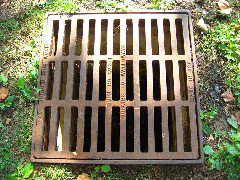
An example of an inlet in Philadelphia When can inlets be used?
Inlets are typically applicable to bioinfiltration/bioretention basins, subsurface infiltration and detention SMPs, and ponds and wet basins. Depending on the site layout and stormwater conveyance design, they may be applicable to cisterns and media filters.
Inlets may be used as an inflow device for any SMP where curb and gutter design is desired or required.
Key advantages of inlets
- Can provide a stable, relatively low-maintenance point for stormwater to enter an SMP
- Allow for pretreatment of stormwater runoff upstream of SMPs
Key limitations of inlets
- Can often result in deeper SMPs than those with curbless design/curb openings due to outlet pipe inverts
- May store and release re-suspended captured sediment during subsequent flows unless frequently maintained
- Can become a source of pollutants through resuspension unless frequently maintained
- Cannot effectively remove soluble pollutants or fine particles
Key design considerations for inlets
- A standard reference for designing traditional drainage systems is U.S. Army Corps of Engineers, Hydraulic Engineering Center Circular 22 (HEC‑22).
- Clogging of an SMP’s distribution piping system can be reduced by equipping upstream inlets with pretreatment devices such as structural screens, hoods, traps, racks, bags, or suspended catch basin inserts.
Figure 4.11‑4: Inlet with typical features
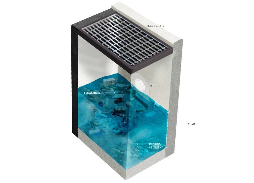
Inlet design and material standards
- Inlets must not be connected in series. Similarly, roof drainage systems must not be directly connected to inlets.
- All inlets must include a sump and trap or sump and hood for pretreatment of stormwater runoff. The sump depth must be at least 15 inches below the bottom of the trap or at least 12 inches below the bottom of the hood.
- If non-standard inlets are used to capture runoff, especially from driveways or roadways where the inlets are not in a sump condition, verification that runoff from the one‑year storm event will be captured by the inlet must be provided.
- Inlet spacing must be designed to prevent water from overtopping the curb and gutter or drainage ditch.
- Inlets must be sized based on the size of the contributing drainage area, the amount of sediment expected from the discharging waters, the size and frequency of runoff events, and the amount of maintenance expected, recognizing that an undersized system will require more frequent maintenance. For large inlet drainage areas, area drains and yard drains 18 inches in diameter or smaller, or smaller than 2’ x 2’, should be upsized to at least 2’ x 2’ inlets.
- All area drains and yard drains 18 inches in diameter or smaller, or smaller than 2’ x 2’, must include a permanent pretreatment device, such as a filter bag insert, for pretreatment of stormwater runoff.
- The designer is referred to the City of Philadelphia Standard Details and Standard Specifications for Sewers booklet and the Philadelphia Plumbing Code, Section P-1001.7 for more design and material guidance.
- All inlets on sites that generate pollutants, such as loading docks, material storage facilities, junk yards, and waste collection and disposal sites, must include a permanent filter bag insert.
Inlet maintenance guidance
Table 4.11‑3 below is a schedule of recommended inspection and maintenance activities for inlets.
Table 4.11‑3: Inlet maintenance guidelines
Ongoing activity Frequency Inspect inlets after several storms to ensure that they are functioning properly and that there are no erosion problems developing. As needed Identify and control source of sediment contamination when in situ soil is exposed or erosion channels are present. As needed Replace filter bags for pretreatment devices. Ensure filter bag is installed properly. Quarterly Inspect all pipe connections and parge ensuring a watertight seal. Quarterly Inspect for sediment and debris build-up. Remove sediment build –up exceeding two inches in depth or if it begins to constrict the flow path.Semiannually Clean out leaves, trash, and debris. Semiannually Maintain records of all inspections and maintenance activity. Ongoing -
4.12 Outlet Controls
4.12.1 Outlet control introduction
Outlet controls regulate the release of stormwater from a stormwater management practice (SMP). Proper design and construction practices are crucial to outlet control performance, which is closely interconnected with SMP performance. They must be appropriately selected and sized for the storage component of the SMP. Small differences in outlet control parameters, such as dimensions and invert elevations, can have drastic effects on SMP outflow characteristics. Examples of outlet controls include orifices, weirs, risers, underdrains, level spreaders, impervious liners, micro siphon drain belts, and low flow devices.
Outlet controls can provide a range of functions including:
- Meeting peak flow requirements;
- Controlling the rate of discharge from the SMP during various storm events;
- Controlling the amount of water stored for infiltration;
- Meeting drain down requirements;
- Providing adequate retention time for Water Quality requirement treatment;
- Bypassing of larger flows (positive overflow) to prevent re-suspension of sediment, hydraulic overload, or erosion of management practices; and/or
- Reducing downstream erosion potential.
Outlet control structures typically consist of concrete boxes that contain one or more outlet controls such as orifices or weirs.
A multi-stage outlet control structure can be designed with multiple orifices and weirs at different elevations to meet varying Philadelphia Water Department (PWD) Stormwater Regulations (Stormwater Regulations). A multi-stage outlet control structure may include several orifices for controlled flow and a positive overflow to quickly pass flow during extreme events.
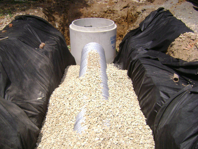
An example of an outlet control structure installation in Philadelphia Design of outlet controls is not limited to the examples shown within this text. The designer must also consider the means and methods of the maintenance activities needed for the long-term operation of the structure and specific controls. Successful stormwater management plans will combine appropriate materials and designs specific to each site.
The following table is a guide to the outlet controls covered in this section showing whether they are typically used in conjunction with various SMP practices. Red indicates that an outlet control would typically be used with an SMP; yellow indicates that the outlet control may be used with the associated SMP in certain circumstances; and blue indicates that the outlet control would not typically be used with the associated SMP.
Table 4.12‑1: Outlet controls applicability guidance
SMP Orifices Weirs Risers Underdrains Level
spreadersImpervious
linersMicro siphon
drain beltsLow flow
devicesPonds and
wet basinsTypical Typical Typical Atypical Typical Typical Occasional Occasional Bioretention Typical Typical Typical Typical Typical Occasional Occasional Occasional Bioinfiltration Typical Typical Typical Typical Typical Atypical Atypical Atypical Subsurface
detentionTypical Typical Atypical Occasional Typical Occasional Occasional Typical Subsurface
infiltrationTypical Typical Atypical Occasional Typical Atypical Atypical Atypical Blue‑green
roofsTypical Occasional Occasional Atypical Atypical Typical Typical Occasional Blue roofs Typical Occasional Occasional Atypical Atypical Typical Atypical Occasional Media filters Occasional Occasional Atypical Occasional Occasional Occasional Occasional Occasional Cisterns Occasional Occasional Atypical Atypical Atypical Occasional Atypical Occasional Drainage
wellsOccasional Atypical Atypical Atypical Atypical Atypical Atypical Atypical Green roofs Atypical Atypical Occasional Atypical Atypical Typical Occasional Occasional Porous
surfacesAtypical Atypical Atypical Occasional Atypical Atypical Atypical Atypical General design standards
(The designer is referred to Appendix L to download a CAD file of the Double Manhole Outlet Control Structure Standard Detail.)
- Outlet controls must be provided as necessary to regulate flow in order to meet all applicable release rate, drain down time, ponding depth, positive overflow, and other requirements.
- Outlet controls must provide positive overflow for their associated SMP, allowing stormwater to flow out of the SMP when the water level reaches a maximum design elevation in a subsurface feature or a maximum ponding depth in a surface feature without surcharging the SMP. Positive overflow from an SMP can either flow to another SMP or to an approved point of discharge. Outlet control structures must be sized to convey at least the ten‑year, 24‑hour storm event without surcharging the structure. The outlet controls must be designed to convey flows from the SMP up to the 100‑year, 24‑hour storm event, or, if the project is exempt from Flood Control, the ten‑year, 24‑hour storm, without surcharging the SMP. If flow reaches the SMP via a flow splitter, this structure can provide the positive overflow. The designer is referred to the SMP Sections within this chapter for SMP-specific design standards.
- Outlet controls must be located so as to be easily and readily accessible for maintenance purposes.
- Subsurface outlet control structures must remain free of any obstruction preventing manhole lids from being removed for accessibility and maintenance.
- Outlet control structures must be sealed with a waterproof membrane, such as bituminous tar or similar.
- A watertight seal for all pipe connections in the outlet control structure must be provided, such as rubberized boot collars, water stop grouting rings with non-shrink grout, or similar.
- Precast structure sections must be interlocked using key joints. Key joints must be fitted with bituminous tar, gaskets, or similar, to prevent water intrusion.
- A watertight seal must be provided between the precast structure and the impermeable weir.
- An anti-seep collar (either a prefabricated anti-seep collar or a bentonite clay trench dam) must be provided on all outlet pipes and be sufficiently sized and distanced from the outlet structure to prevent water from traveling along the outside of the outlet pipe. Anti-seep collars must be constructed in accordance with the latest edition of the PA DEP Erosion and Sediment Pollution Control Program Manual.
- All outlet control structures in combined sewer areas must include a sump and trap or sump and hood. The sump depth must be at least 15 inches below the bottom of the trap or at least 12 inches below the bottom of the hood, and the traps or hoods must be air-tight. The designer is referred to the City of Philadelphia Water Department Standards Details and Standard Specifications for Sewers and the Philadelphia Plumbing Code Section P-1001.7 for additional guidance.
- Ladder bars must be included within any outlet control structure.
- Any manholes between outlet structures and sewer connections in combined sewer areas must have sanitary, non-vented covers.
- Outlet control structures must have solid, non-grated, tops.
- The outlet pipe of an outlet control structure must have an invert at or below the invert of the inlet pipe(s). Setting the outlet pipe invert at a minimum of 7.5 inches below that of the inlet pipe(s) is recommended.
- The outlet pipe of an outlet control structure directed to the City sewer may not be designed to be used as flow attenuation for its associated SMP. Upstream outlet control devices, such as an orifice or weir, must control the flow for all design storms up to, and including, the 100‑year storm.
- Proprietary and subscription-based active outlet controls must be designed with a passive default control that complies with applicable Stormwater Regulations in the case that the subscription is canceled or lapsed.
Outlet control construction guidance
Proper installation of outlet controls is essential to long-term function. Outlet controls must be installed per the following construction sequence:
- Install all temporary erosion and sedimentation controls in the immediately adjacent work areas in accordance with the latest edition of the Pennsylvania Department of Environmental Protection (PA DEP) Erosion and Sediment Pollution Control Program Manual prior to construction.
- If excavation is required, clear the areas to be excavated of all vegetation. Remove all tree roots, rocks, and boulders in excavation areas.
- Excavate areas to desired elevation (if necessary).
- If using an underdrain, place filter fabric or pea gravel filter, then place the rock and set the underdrain according to the plans. Otherwise, prepare subgrade for outlet structures.
- Install outlet controls according to plans. Outlet controls must be constructed in accordance with manufacturer’s guidelines or the design professional’s guidance. Ensure outlet control structures are properly sealed and waterproofed to prevent leakage. Outlet controls must comply with all applicable American Society of Testing and Materials (ASTM) testing methods as required by PWD.
- Confirm invert elevations and dimensions of outlet controls prior to final backfill and compaction of surrounding areas.
- Backfill and compact areas around outlet controls. Ensure backfill is properly compacted in accordance with specifications.
- Once site vegetation is stabilized, remove erosion and sediment control measures.
Outlet control maintenance guidance
General recommended maintenance activities for outlet controls are summarized in Table 4.12‑2.
Table 4.12‑2: Outlet controls maintenance guidelines
Ongoing activity Frequency Inspect outlet control structures after several storms to ensure that they are functioning properly and that there are no erosion problems developing. As needed Identify any sources of sediment contamination and control when in situ soil is exposed or erosion channels are present. As needed Maintain and cut back vegetation directly surrounding outlet control structures if impairing function of SMP. As needed Clean out leaves, trash, and debris, from all structures, such as grates and orifices (Note: consult with professional vacuum cleaning service if subsurface pipes, including underdrains, appear to be clogged). As needed Inspect all pipe connections and parging ensuring a watertight seal. Quarterly Remove all trash, sediment, and debris accumulation from the orifice. Quarterly Remove all trash, sediment, and debris build-up on the trash rack. Quarterly Inspect for sediment and debris build-up. Sediment build-up that begins to constrict the flow path must be removed. Quarterly Maintain records of all inspections and maintenance activity. Ongoing 4.12.2 Orifices
An orifice is a circular or rectangular opening of a prescribed shape and size that allows a controlled rate of release for outflow from an SMP when the orifice is submerged.
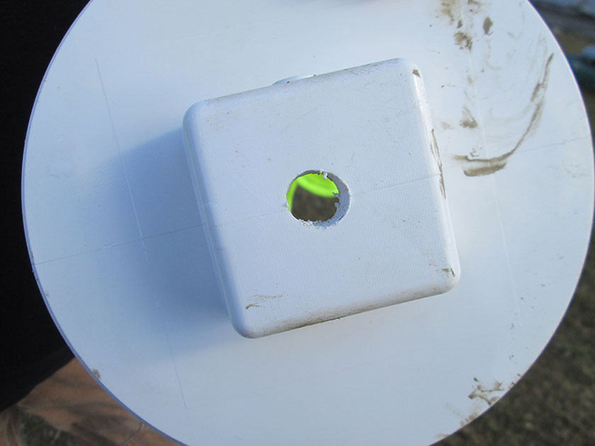
An example of an underdrain orifice in Philadelphia When can orifices be used?
An orifice is an outlet control that is typically applicable to bioinfiltration/bioretention basins, subsurface infiltration and detention SMPs, ponds and wet basins, and blue roofs. Depending on the site layout and stormwater conveyance design, they may be applicable to cisterns and media filters.
Orifices are suitable for SMPs of any size and can be used in conjunction with other outlet controls, such as weirs, to meet the Stormwater Regulations, if necessary.
Key advantages of orifices
- Are simple, passive structures that rely on gravity flow
- Can be variously sized to provide rate control for a wide variety of applications
- Multiple orifices may be located at the same or different elevations, if necessary, to meet performance requirements
- Allow for controlled drain down times
Key limitations of orifices
- May become clogged with sediment and debris, particularly traditional orifices with small diameters
- May be difficult to access for maintenance purposes when placed below grade
- Can concentrate flow and may cause erosive velocities
Key design considerations for orifices
- Multiple orifices may be necessary to meet the Stormwater Regulations.
- Sizing is dependent upon release rate requirements, maximum ponding depth, and drain down time requirements.
- The orifice size that is needed to meet a certain release rate can be increased by reducing the head over the orifice, which can be achieved by enlarging the SMP’s footprint or adjusting overlying soil depths/cover for orifices below grade.
- Low flow devices can allow smaller release rates with larger orifices. The designer should explore all options before choosing a small orifice. The designer is referred to Section 4.12.9 for further information on low flow devices.
Figure 4.12‑1: Orifice with typical features

Orifice design and material standards
- No underdrain orifice (i.e., that which is located at the capped end of an underdrain) may be smaller than 0.5 inches in diameter. No traditional orifice (i.e., that which is not part of an underdrain) may be smaller than one inch in diameter. (The designer is referred to Appendix L to download a CAD file of the Underdrain Connection Standard Detail.)
- Trash racks must be provided for all orifices draining surface basins.
- To prevent clogging, screening must be provided over any traditional orifice three inches in diameter or smaller. The dimensions of the openings within the screening must be half the diameter of the orifice. The screening should be separated from the orifice, not placed directly over the orifice. A minimum 12‑inch sump must be provided beneath the invert of the orifice to prevent the collection of debris.
- One manhole access lid on each side of the orifice is required for maintenance access. The manholes must be located no farther than two horizontal feet from the orifice. Adequate space to perform maintenance on the orifice must be provided; it is recommended that at least four feet by three feet of space be provided on each side of the orifice.
- Orifices must be designed and constructed of appropriate materials, taking flow velocities and exposure to the elements into consideration.
- Suitable access must be provided to inspect and maintain all orifices.
4.12.3 Weirs
Weirs are engineered barriers/dams designed to control the release of stormwater from SMPs. Weirs can be located within surface SMPs or open channels or within outlet control structures. Typical weir shapes are rectangular, V-notch, and trapezoidal. Weir crests can be either sharp or broad.
Impermeable weirs controlling overland flow paths, such as swales, are typically called check dams. Impermeable check dams control upstream stormwater ponding depths and can be used to promote infiltration and/or sedimentation.
Check dams are permeable weirs that promote sedimentation by slowing flow velocities as water ponds behind the weir. Under low flow conditions, water ponds behind the check dam and slowly seeps through the openings between the permeable weir materials. Under high flow conditions, water flows both over and through the weir. Check dams also provide a means of spreading runoff as it is discharged, helping to decrease concentrated flow and reduce velocities as the water travels downstream. Stone check dams are typically located within overland flow paths, such as swales.
Spillways are weir outlet controls that are designed to provide safe, positive overflow from SMPs that store water on the surface, such as bioinfiltration/bioretention basins and ponds and wet basins. Spillways are typically trapezoidal, earthen, broad-crested weirs lined with riprap that allow for controlled flow of water over an SMP storage berm during extreme events.
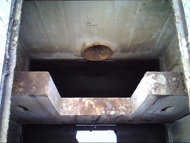
An example of a weir in Philadelphia When can weirs be used?
A weir is an outlet control that is typically applicable to bioinfiltration/bioretention basins, subsurface infiltration and detention SMPs, and ponds and wet basins. Depending on the site layout and stormwater conveyance design, they may be applicable to blue roofs, cisterns, and media filters.
Weirs are suitable for SMPs of any size and can be used in conjunction with other outlet controls, such as orifices, to meet the Stormwater Regulations, if necessary. Sizing of weirs is dependent upon release rate requirements, maximum ponding depth, and drain down time requirements.
Weirs can be used to do the following:
- Increase storage within surface depressions such as swales;
- Encourage ponding in areas where settling of solids and infiltration through vegetation and soil media can occur;
- Discharge overflow or bypass flow within an SMP to downstream conveyance systems; and/or
- Dissipate energy, reduce peak release rates, and control erosion.
A check dam is typically applicable to ponds and wet basins and swales. Depending on the site layout and stormwater conveyance design, check dams may also be applicable to bioinfiltration/bioretention basins. Stone check dams, placed in a ditch or swale, allow for water to flow through the weir, as opposed to an impermeable weir. Check dams are most often used in large drainage areas within regional SMPs.
A spillway is typically applicable to bioinfiltration/bioretention basins and ponds and wet basins.
Figure 4.12‑2: Weir with typical features
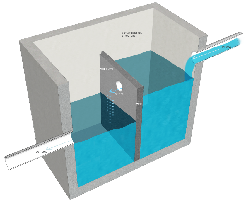
Key advantages of weirs
- Are easily maintained
- May be surface-level structures that can usually be more easily accessed and maintained than closed systems
Key limitations of weirs
- Can concentrate flow and may cause erosive velocities
- Are not typically an effective technology for providing controlled discharge of stormwater
- Check dams may become clogged over time, and, once clogged, would likely require full replacement
Key design considerations for weirs
- Check dams can include decorative stone caps.
- One stone size for a stone check dam is recommended for ease of construction. However, if two or more stone sizes are used, a larger stone should be placed on the outer layer and downstream side, since flows are concentrated at the exit channel of the weir. Several feet of smaller stone can then be placed on the upstream side. Smaller stone may also be more appropriate at the base of the dam for constructability purposes.
Figure 4.12‑3: Check dam with typical features
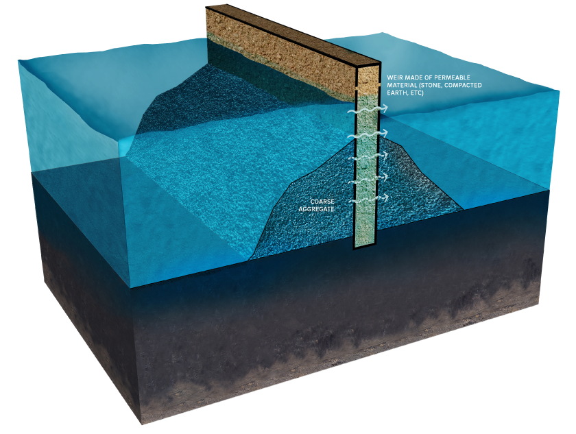
Weir design and material standards
- Design of weirs must consider structural stability during extreme conditions, including flow velocities and upstream hydrostatic pressure from ponded water. Structural supports must be designed by a structural engineer.
- Weirs must be designed and constructed with appropriate materials taking flow velocities and their exposure to the elements into consideration.
- Impermeable weirs in outlet control structures
- Weir walls must consist of concrete that is poured monolithically, and the sides and bottom of the weir must be tied into the outlet control structures using rebar reinforcement.
- Weir walls must have a minimum thickness of six inches.
- Weir walls must be entirely watertight, including the sides and bottom of the weir wall.
- A minimum of 18 inches of clearance must be provided above the top of the weir wall.
- One manhole access lid on each side of the weir wall is required for maintenance access. The manholes must be located no farther than two horizontal feet from the weir wall.
- Check dams
- When placed within swales, check dams must be evenly spaced and no more than six to 12 inches high.
- Check dams that provide ponding in swales and are designed for infiltration must not be porous, as water should be ponded behind each check dam and forced to infiltrate.
- Spillways
- A minimum of one foot of freeboard must be provided between the ponding elevation during the 100‑year, 24‑hour storm event, or, if the project is exempt from Flood Control, the ten‑year, 24‑hour storm, and the invert elevation of the emergency spillway.
- A minimum of one foot must be provided between the invert elevation of the emergency spillway and the top-of-berm elevation.
- All emergency spillways must be stabilized with stone, geotextile, or plant material that can withstand strong flows.
- Spillway flow must not be directed toward neighboring properties.
Figure 4.12‑4: Spillway with typical features
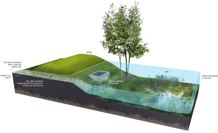
4.12.4 Risers
Risers are vertical structures with a grated top that can be designed to control the amount of water ponded within an SMP and to provide positive overflow. Riser pipes are vertical pipes topped with a dome-shaped grate. Riser boxes are modified concrete boxes (outlet control structures) outfitted with inlet grates. Orifices may also be placed on the upstream face and sides of a riser box to create a multi-stage riser.
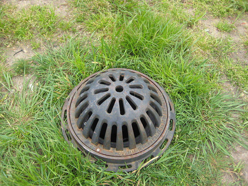
An example of a domed riser pipe in Philadelphia When can risers be used?
A riser is an outlet control that is typically applicable to bioinfiltration/bioretention basins, and ponds and wet basins. Depending on the site layout and stormwater conveyance design, they may be applicable to blue roofs and green roofs. Risers can be used to control ponding depths and release water at a reduced rate. Risers can be used in conjunction with orifices, weirs, or underdrains, as necessary, to meet the Stormwater Regulations.
Key advantages of risers
- Provide flexible outlet controls, when multi-staged, to meet varying Stormwater Regulations simultaneously
Key limitations of risers
- Can be aesthetically displeasing
Key design considerations for risers
- Concrete form liners and surrounding risers with vegetation can be used to improve aesthetics.
- Location of a riser is important to provide easy maintenance access, and risers should not be placed near inflow structures in order to avoid shortcutting of treatment.
Figure 4.12‑5: Riser pipe with typical features
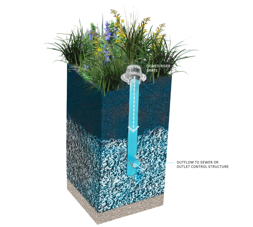
Riser design and material standards
(The designer is referred to Appendix L to download a CAD file of the Riser Outlet Control Structure Standard Detail.)
- Riser design must balance providing positive overflow with allowing for adequate static storage. Overflow must be provided at the maximum Water Quality storm ponding depth for all SMPs and, for bioinfiltration/bioretention basins, at the minimum height to provide sufficient static storage of the Water Quality Volume (WQv).
- Riser pipes must be constructed of high-density polyethylene (HDPE) plastic, corrugated metal, concrete, or other weather resistant material.
- Riser boxes must be constructed of precast or cast-in-place concrete with reinforcing as warranted. All concrete must be Class C, conforming to the specifications of the City of Philadelphia Department of Streets, Standard Construction Items (1997).
- Trash racks or screens are required and must be constructed of durable, weather-resistant materials resistant to photo-degradation, weathering, oxidation, or other corrosive impacts.
4.12.5 Underdrains
Underdrains are typically perforated pipes in stone layers or trenches that intercept, collect, and convey stormwater that has percolated through soil, a suitable aggregate, and/or geotextile, in order to drain the SMP after a storm event, allowing its storage volume to be available for subsequent storms. Underdrains can be connected to an outlet control structure that then controls the ponding elevation or release rate through weirs and/or orifices.
When can underdrains be used?
An underdrain is an outlet control that is typically applicable to bioinfiltration/bioretention basins. Depending on the site layout and stormwater conveyance design, they may be applicable to porous surfaces, subsurface infiltration and detention SMPs, and media filters.
Underdrains can be used to collect runoff from media storage beds for non-infiltrating SMPs. Underdrains can be used when sub-soils are not appropriate for infiltration (e.g., karst geology, massive structure, known contaminants, etc.).
Capped underdrains are required for all bioinfiltration/bioretention SMPs. The designer is referred to Section 4.1 for design guidance on flow-regulating underdrains for bioinfiltration/bioretention SMPs.
Key advantages of underdrains
- Can collect stormwater over a large surface area
- Allow for vegetative and media filtration prior to release of stormwater into downstream conveyance systems
- Allow for vegetated or filtering practices to be placed in areas where infiltration is infeasible
Key limitations of underdrains
- May require maintenance, inspection, and replacement that can be difficult since the systems are typically buried underneath stone and, sometimes, soil
- Can experience inhibited performance due to root intrusion, if not properly controlled
Key design considerations for underdrains
- To help prevent or minimize the potential for root intrusion, trees with aggressive root systems should be located away from underdrains.
Figure 4.12‑6: Underdrain with typical features
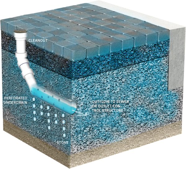
Underdrain design and material standards
(The designer is referred to Appendix L to download CAD files of the Underdrain Connection and Orifice Standard Details.)
- Underdrains are required for all bioinfiltration/bioretention SMPs. For bioinfiltration SMPs, a solid cap must be provided at the end located within the outlet control structure to promote infiltration. For bioretention SMPs located in the combined sewer area, a cap must be provided at the end located within the outlet control structure, and it must be outfitted with an orifice, sized appropriately to meet all applicable release rate requirements.
- Underdrains must be designed to be level (i.e., with no slope).
- Underdrains must be made of continuously perforated HDPE plastic piping with a smooth interior and a minimum inner diameter of four inches. HDPE pipe must meet the specifications of AASHTO M252, Type S or AASHTO M294, Type S.
- Underdrains must be surrounded by a sand or stone layer to filter sediment and facilitate drainage.
- The minimum allowable thickness of a sand or stone filter layer is six inches both above and beneath the underdrain.
- To prevent clogging, underdrain pipes must be surrounded by geotextile fabric if a sand layer is used.
- Stone surrounding an underdrain must be uniformly graded, crushed, clean-washed stone. PWD defines “clean-washed” as having less than 0.5% wash loss, by mass, when tested per AASHTO T-11 wash loss test. AASHTO No. 3 and No. 57 stone can meet this specification.
- Sand, if used, must be AASHTO M‑6 or ASTM C‑33 sand and must have a grain size of 0.02 inches to 0.04 inches.
- Geotextile fabric must be placed between the stone layer and surrounding soil to prevent sediment contamination.
- Geotextile must consist of polypropylene fibers and meet the following specifications (AASHTO Class 1 or Class 2 geotextile is recommended):
- Grab Tensile Strength (ASTM-D4632): ≥ 205 lbs
- CBR Puncture Strength (ASTM-D6241): ≥ 500 lbs
- Flow Rate (ASTM-D4491): ≥ 95 gal/min/ft2
- UV Resistance after 500 hrs. (ASTM-D4355): ≥ 70%
- Tear Resistance (ASTM-D4533): ≥ 80 lbs
- Heat-set or heat-calendared fabrics are not permitted.
- Cleanouts or maintenance access structures must be provided at the end of all underdrain pipes.
- Cleanouts must be provided for all 90-degree bends, located upstream of complicated bends, and evenly spaced during straight pipe runs.
- All intermediate cleanouts and domed riser pipe connections must be located upstream of the connected outlet control structure to allow for cleaning equipment to flush in the direction of the structure.
- An anti-seep collar must be installed around outlet pipes passing through embankments. Anti-seep collars must be constructed in accordance with the latest edition of the PA DEP Erosion and Sediment Pollution Control Program Manual.
- Cleanouts must be made of material with a smooth interior having a minimum inner diameter of six inches. If the connecting pipe is eight inches in diameter or larger, then the cleanout must be eight inches in diameter.
- The outlet pipe of an outlet control structure must have an invert at or below the invert of the underdrain. Setting the outlet pipe invert at a minimum of 7.5 inches below that of the underdrain is recommended.
4.12.6 Level spreaders
Level spreaders are outlet controls that are designed to uniformly distribute concentrated flow over a large area. Level spreaders help reduce concentrated flow, thereby reducing erosion and increasing the design life of many SMPs.
All level spreader designs follow the same principles:
- Concentrated flow enters the spreader at a single point such as a pipe, swale, or curb opening.
- The flow is slowed, and energy is dissipated.
- The flow is distributed throughout a long, linear, shallow trench or behind a low berm.
- Water then flows over the berm or edge of trench uniformly along the entire length.
There are many types of level spreaders that can be selected based on the peak rate of inflow, the duration of use, and the site conditions. Examples of level spreaders include subsurface discharge through level perforated pipes (bubble-up level spreader), concrete curbs, half-sections of pipe, troughs, and surface discharge to plunge pools.
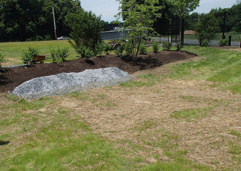
An example of a level spreader in Philadelphia When can level spreaders be used?
A level spreader is an outlet control that is typically applicable to bioinfiltration/bioretention basins, ponds and wet basins, and subsurface infiltration and detention SMPs. Depending on the site layout and stormwater conveyance design, they may be applicable to media filters. They are suitable as outlet controls for pretreatment structures such as forebays and at locations where SMPs cannot discharge to the City sewer and/or must outfall to open spaces. Plunge pools can be used in combination with concrete curbing and/or trough level spreaders.
Key advantages of level spreaders
- Reduce velocities, reducing the potential for erosive conditions
- Eliminate the need for larger outlets and/or conveyance systems in some instances
Key limitations of level spreaders
- Not effective for providing rate control
- Have strong failure potential if soils are not protected from compaction and settlement; performance is strongly influenced by relatively small changes in elevation
- Require a relatively flat grade and downslope pervious areas onto which the spread flow can be discharged
- Can require 100 feet in downstream length in certain scenarios
- May be rendered ineffective by high sediment load deposition on the surface
Key design considerations for level spreaders
- The depths of trough or pipe level spreaders will depend on the flow. If sediment or debris accumulates in the trough or pipe, it can be easily removed.
- Concrete troughs are generally a more expensive level spreader alternative; however, they are easy to maintain and typically have a longer design life.
- Long-term maintenance and replacement costs can be decreased with proper installation.
Figure 4.12‑7: Level spreader with typical features
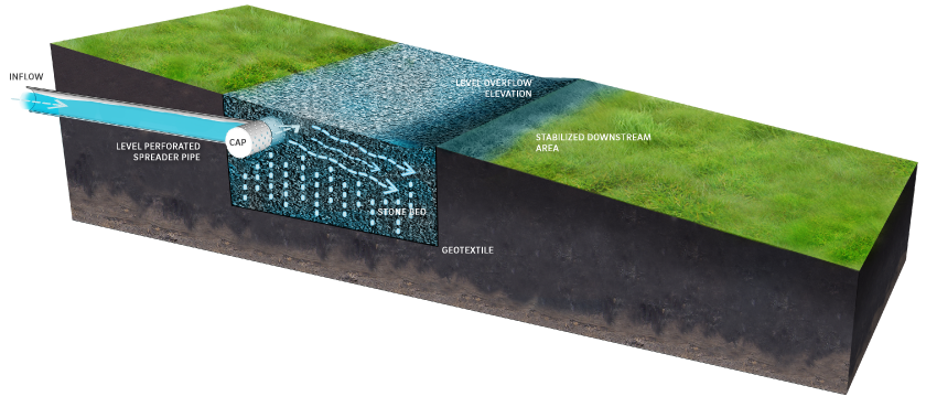
Level spreader design and material standards
- The following level spreader lengths are required by cover condition:
- Dense grass ground cover: 13 linear feet for every one cubic feet per second (cfs) of flow during the ten‑year, 24‑hour storm event
- Forested areas with no ground cover: 100 linear feet for every one cfs of flow during the ten‑year, 24‑hour storm event
- Level spreaders must safely diffuse flows up to, and including, the 100‑year, 24‑hour storm event.
- It is critical that the edge over which flow is distributed is exactly level. If there are small variations in height on the downstream lip, small rivulets will form. Experience suggests that variations of more than 0.25 inches can cause water to re-concentrate and potentially cause erosion downstream of the level spreader. The site selected for the installation of a level spreader must be a level grade (a constant horizontal elevation, to within +/- four inches).
- The downslope side of the level spreader must be clear of debris. After construction, debris such as soil, wood, and other organic matter might accumulate immediately downstream of the level spreader. This effectively blocks water as it flows out of the level spreader, forcing it to re-concentrate.
- The downstream side of the level spreader must be fully stabilized before the level spreader is installed. If a level spreader is installed above a disturbed area without sufficient vegetative cover or other ground cover such as mulch or construction matting, erosion rills will quickly form. Even sheet flow can cause significant downstream erosion on disturbed areas. The first three feet downslope of a level spreader must be stabilized with soil/turf reinforcement matting and grass or other approved vegetation.
- Level spreaders cannot be constructed in newly deposited fill. Undisturbed earth is much more resistant to erosion than fill. Erosion is even likely to occur over a well-established young stand of grass planted fill.
- For level spreaders that do not direct discharge to a receiving stream or sewer, the minimum distance between the level spreader and any downslope property boundary must be 15 feet. If this requirement cannot be met, a drainage easement may be required.
- For level spreaders that direct discharge to a receiving stream or sewer via overland flow, the maximum distance between the level spreader and any receiving stream or sewer must be 100 feet. Distances greater than 100 feet but less than 150 feet may be considered on a case-by-case basis for very mild slopes (less than or equal to 1%) and heavily vegetated (grassy) areas.
- The first ten feet downslope of the level spreader must not exceed a slope of 4%.
- Earthen berms must not be used as level spreaders due to the difficulty of grading a level edge within acceptable tolerances.
- Treated lumber must not be used as level spreaders due to issues with deformation and decomposition.
- Geotextile-covered berms must not be used as level spreaders.
- Concrete curbs, troughs, and half-pipes:
- Concrete curbs, troughs, and half-sections of pipe must be between four and 12 inches deep.
- Curbs and troughs must be constructed of Class C concrete or reinforced concrete, conforming to the specifications of the City of Philadelphia Department of Streets, Standard Construction Items (1997).
- Half-pipes must be either Class C concrete or reinforced concrete, conforming to the specifications of the City of Philadelphia Department of Streets, Standard Construction Items (1997) or HDPE plastic meeting the specifications of AASHTO M252, Type S or AASHTO M294, Type S.
- Subsurface discharge through level perforated pipes (bubble-up level spreaders)
- Perforated pipes must be between four and 12 inches in diameter. HDPE pipe must meet AASHTO M252, Type S or AASHTO M294, Type S standards.
- The pipes must be enveloped in uniformly graded, crushed, clean-washed stone. PWD defines “clean-washed” as having less than 0.5% wash loss, by mass, when tested per AASHTO T-11 wash loss test. AASHTO No. 3 and No. 57 stone can meet this specification.
- Geotextile must be placed between the stone aggregate and soil.
- Geotextile must consist of polypropylene fibers and meet the following specifications (AASHTO Class 1 or Class 2 geotextile is recommended):
- Grab Tensile Strength (ASTM-D4632): ≥ 205 lbs
- CBR Puncture Strength (ASTM-D6241): ≥ 500 lbs
- Flow Rate (ASTM-D4491): ≥ 95 gal/min/ft2
- UV Resistance after 500 hrs (ASTM-D4355): ≥ 70%
- Tear Resistance (ASTM-D4533): ≥ 80 lbs
- Heat-set or heat-calendared fabrics are not permitted.
- Perforated pipes must include end treatments consisting of cleanouts, inlets, or manholes for maintenance purposes.
- Surface discharge to plunge pools
- Underlying soils within plunge pools must remain undisturbed, uncompacted, and protected from heavy equipment to preserve infiltration capacities.
- Riprap stone sizing must be determined in accordance with the riprap apron design procedures in the latest edition of the PA DEP Erosion and Sediment Pollution Control Program Manual.
Level spreaders maintenance guidance
General recommended maintenance activities for level spreaders are summarized in Table 4.12‑3.
Table 4.12‑3: Level spreader maintenance guidelines
Ongoing maintenance activity Frequency Inspect for debris and sediment accumulation in the forebay, along the stone, in the pipe, and along the downslope side of the level spreader. Remove all debris and sediment. Quarterly Inspect the downstream side of the level spreader for erosion. Quarterly Remove all vegetation from areas of stone. Monthly during the growing season Mow/trim vegetation on the downstream side of the level spreader. Monthly during the growing season Inspect level spreader after storms to ensure there is sufficient stone to diffuse flow and replace as needed Concurrent with storm events Inspect the edge over which flow is distributed for levelness. Eliminate variations in height on the downstream lip. Quarterly Inspect the level spreader site for levelness. Ensure a constant horizontal elevation. Quarterly 4.12.7 Impervious liners
Impervious, or impermeable, liners prevent water from crossing a system boundary such as infiltrating through the subgrade beneath an SMP. Impervious liners include, but are not limited to, compacted till liners, clay liners, geomembrane liners, and concrete liners.

An example of an impervious liner installation in Philadelphia When can impervious liners be used?
An impervious liner is an outlet control that is typically applicable to green roofs and blue roofs. Depending on the site layout and stormwater conveyance design, they may be applicable to bioretention basins, cisterns, ponds and wet basins, and subsurface detention SMPs. Impervious liners are only permitted in instances where placement is over in situ soils in which infiltration is restricted due to geotechnical concerns, such as over contaminated soils and brownfields, adjacent to subsurface structures, or adjacent to sewer infrastructure.
Key advantages of impervious liners
- Prevent infiltration in areas of contamination, adjacent to subsurface structures, or adjacent to sewer infrastructure in need of protection from potential flooding or seepage
Key limitations of impervious liners
- Not readily visible for maintenance inspections
- Typically require significant excavation to repair
Key design considerations for impervious liners
- Impervious liners are not required for all non-infiltrating SMPs. For example, even if the infiltration potential of underlying soils is limited due to low infiltration rates, bioretention SMPs must be constructed without impervious liners.
- Clay liners should be of an appropriate design as specified by a geotechnical engineer.
Figure 4.12‑8: Impervious liner with typical features
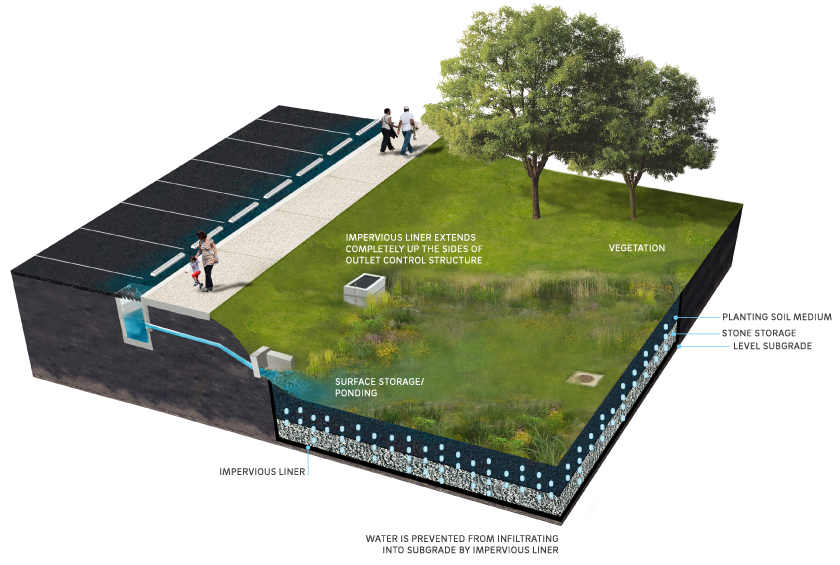
Impervious liner design and material standards
- Impervious liners are required, as appropriate, to prevent infiltration into areas of soil contamination.
- Impervious liners, if needed, must be installed to prevent infiltration SMPs from infiltrating stormwater within the zone of influence of any nearby sewers or sewer laterals. The zone of influence is defined by the area within a 1:1 (H:V) slope line from the outer edge of a sewer or sewer lateral.
- All impervious liners must exhibit a permeability less than or equal to 10-6 cm/sec.
- Impervious liners must be continuous and extend completely up the sides of any structures that are located within the lined basin footprint to the ground surface. If additional liner material must be added to extend up the structures, the additional liner sections must be joined to the rest of the liner with an impervious seam per the manufacturers’ recommendation.
- Compacted till liners:
- The minimum allowable compacted till liner thickness is 18 inches (after compaction).
- Soil must be compacted to 95% minimum dry density, modified proctor method (ASTM D-1557).
- Soil must be placed in six‑inch lifts.
- Soils to be used must meet the gradation in Table 4.12‑4:
Table 4.12‑4: Compacted till liner soil gradation
Sieve size Percent passing 6‑inch 100 #4 70–100 #200 20 - Clay liners
- The minimum allowable clay liner thickness is 12 inches (after compaction).
- Clay liners must conform to the specifications outlined in Table 4.12‑5, per the Stormwater Management Manual for Western Washington (2012):
Table 4.12‑5: Clay liner specifications
Property Test method Unit Specifications Permeability ASTM D-2434 cm/sec 1 x 10⁻⁶ max. Plasticity index of clay ASTM D-423 & D-424 Percent Not less than 15 Liquid limit of clay ASTM D-2216 Percent Not less than 30 Clay particles passing ASTM D-422 Percent Not less than 30 Clay compaction ASTM D-2216 Percent 95% of Standard Proctor Density - Geomembrane liners
- Geomembrane liner material must be polyvinyl chloride (PVC), polypropylene (PP), linear low-density polyethylene (LLDPE), or high-density polyethylene (HDPE).
- PVC geomembranes must have a thickness of 30 mil and must conform to the physical requirements stipulated in ASTM D7176: Standard Specification for Non-Reinforced Polyvinyl Chloride (PVC) Geomembranes Used in Buried Applications.
- PP geomembranes must have a thickness of 30 or 36 mil and must conform to the physical requirements stipulated in the Geosynthetic Research Institute (GRI) GM18 Standard Specifications for PP geomembranes.
- LLDPE geomembranes must have a thickness of 40 mil and must conform to the physical requirements stipulated in the Geosynthetic Research Institute (GRI) GM17 Standard Specifications for LLDPE geomembranes.
- HDPE geomembranes must have a thickness of 60 mil and must conform to the physical requirements stipulated in the Geosynthetic Research Institute (GRI) GM13 Standard Specifications for HDPE geomembranes.
- Geomembrane liner material must be resistant to mildew, rot, ultraviolet radiation, insects, and rodents.
- For fully-lined SMPs, geotextile must be placed on either side of the entire geomembrane liner to protect it from the in-situ soil outside the liner and the overlying stone or soil storage inside the liner. The geotextile must meet, or exceed, the strength properties outlined in Table 4.12‑6.
- For partially-lined SMPs, geotextile must be placed on either side of the geomembrane liner to protect it from the in-situ soil outside the liner and the overlying stone or soil storage inside the liner. The geotextile placed outside the liner must meet, or exceed, the strength properties outlined in Table 4.12‑6. The geotextile placed between the liner and the overlying stone or soil storage must be in accordance with the geotextile specifications listed within the respective SMP’s “Storage Area Material Standards” elsewhere in Chapter 4.
- A minimum four‑inch sand layer must be placed beneath the geomembrane liner and geotextile to provide a stable, even bottom and prevent uneven settling and punctures to the liner.
- Boot collars must be included at any point where a pipe penetrates a geomembrane liner. This includes utility crossings, distribution pipes, and underdrain pipes.
- Geomembrane liner material must be polyvinyl chloride (PVC), polypropylene (PP), linear low-density polyethylene (LLDPE), or high-density polyethylene (HDPE).
Table 4.12‑6: Geotextile strength properties for impervious liner protection
Geotextile property Test method Geotextile property requirements* Weight ASTM D5261 ≥ 16 oz./sq. yd. Grab Tensile Strength, in machine and x-machine direction ASTM D4632 ≥ 380 lbs. Grab Failure Strain, in machine and x-machine direction ASTM D4632 > 50% Seam Breaking Strength (if seams are present) ASTM D4632 and ASTM D4884 (adapted for grab test) ≥ 220 lbs. Puncture Resistance ASTM D4833 ≥ 180 lbs. Tear Strength, in machine and x-machine direction ASTM D4533 ≥ 145 lbs. Ultraviolet (UV) Radiation ASTM D4355 ≥ 70% strength stability retained, after 500 hrs. in weatherometer *Average roll values. Test results must meet or exceed these values. - Concrete liners:
- Concrete must be minimum five inches thick, Class A or better, with ordinary surface finish.
- When underlying soil is clay or if it has an unconfined compressive strength of 0.25 tons per square foot or less, the concrete must have a minimum six‑inch compacted aggregate base composed of coarse sand and river stone, crushed stone, or equivalent, with diameter of 0.75 inch to one inch.
4.12.8 Micro siphon drain belts
Micro siphon drain belts are drainage systems that use capillary pressure to wick water out of the soil or filter media and convey it through small siphon channels to collector drainpipes. They are typically flexible, extruded, PVC strips of variable widths with micro channels on one side. The belts can be installed at various depths within filter media or underlying soil, and their flexible shape can contour to the shape of the installed surface. Micro siphon drain belts may be used in combination with other techniques, such as layering of porous media to regulate outflow. They can also be connected to underdrains and used in conjunction with outlet control structures.
When can micro siphon drain belts be used?
Depending on the site layout and stormwater conveyance design, micro siphon drain belts may be applicable to bioretention basins, subsurface detention SMPs, ponds and wet basins, green roofs, blue‑green roofs, and media filters. Micro siphon drain belts can be used in conjunction with underdrains and impervious liners when infiltration is not feasible. For example, they can be used to collect and convey drainage from a large area to a central underdrain. They can also be used for applications in which water must be drawn away from foundations, retaining walls, or other boundaries.
Key advantages of micro siphon drain belts
- Can meet very low release rate requirements
- Can collect stormwater over a large surface area
- Allow for vegetative and media filtration prior to the release of stormwater back into downstream conveyance systems
- Resist clogging, as the capillary action that pulls water into the micro channels does not transport solids
- Constructed of material that is both flexible and durable, making the belts easy to install and resistant to compression or other degradation over time
Key limitations of micro siphon drain belts
- Have limited system depth due to maximum allowable head
- Do not allow for inspection of system without excavation
Key design considerations for micro siphon drain belts
- Installation with the micro channels facing downward limits clogging of the micro channels, as gravity allows particulates to fall out when water is pulled into the micro siphon channels.
- To help prevent or minimize the potential for clogging by root intrusion, locate trees and plants with aggressive root systems away from micro siphon drain belts.
Figure 4.12‑9: Micro siphon drain belt application in a blue‑green roof

Micro Siphon Drain Belt application in a Blue-Green Roof Micro siphon drain belt design and material standards
- Micro siphon drain belts must connect to a downslope underdrain or collector pipe. The elevation of the belt in the immediate vicinity of the downslope connection must be at least four inches above the top of the underdrain or collector pipe. Alternatively, for vegetated SMPs on-structure where depth is limited, such as blue‑green roofs, a belt slope of 1% to 2%, with a curve of the tail of the belt down to the connection pipe, must be maintained.
- The end of the micro siphon drain belt that is not connected to the collector pipe must be sealed to prevent the intrusion of solids or other clogging materials. The sealant must be suitable for use in submerged environments.
- A minimum belt slope of 1% is required to ensure drainage, but a belt slope of 3% to 5% is recommended to maintain laminar flow within the micro channels.
- Micro siphon drain belts must be installed in a layer of sand. Sand used must be ASTM C‑33 aggregate concrete sand with grain size between 0.02 inches and 0.08 inches. Alternatively, for vegetated SMPs on-structure where depth is limited, such as blue‑green roofs, the micro siphon drain belt may be installed in the foundation growing medium layer with a minimum depth of 0.25 inches of media below the belt or per manufacturer’s recommendations.
- Manufacturer’s recommendations must be followed to determine the number, size, and specific configuration of belts required to provide adequate flow capacity for specific applications.
- Flow rate for an eight‑inch-wide micro siphon drain belt with a minimum saturated cover (head) of four inches is calculated as follows. The calculated flow rate can be divided by two for a four‑inch-wide micro siphon drain belt.
4.12.9 Low flow devices
Low flow devices are prefabricated or proprietary systems that regulate the discharge flow rate from SMPs. Types of low flow devices include, but are not limited to, floating or constant-head orifices and vortex outlet control devices. Floating, or constant-head, orifices regulate low flow discharges through the use of a floating intake structure. Vortex outlet control devices use induced helical flow to restrict flow rates.
Low flow devices are evaluated on a project-specific basis since site conditions, such as sediment loading and/or drainage area size, can impact a product’s ability to meet Stormwater Regulations. PWD has developed a list, accessible on the PWD Development Services Resource Directory, of low flow devices that may be used to comply with the Stormwater Regulations.
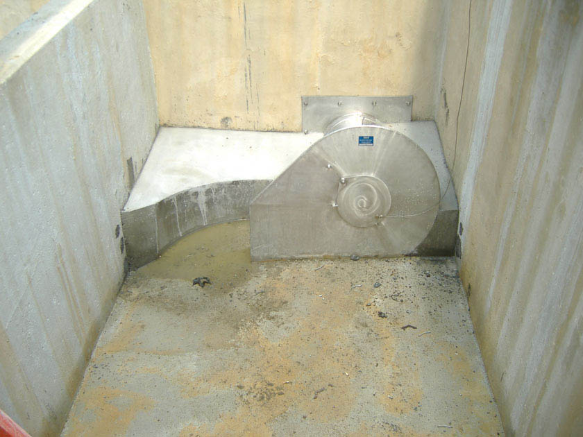
An example of a low flow device in Philadelphia When can low flow devices be used?
A low flow device is an outlet control that is typically applicable to subsurface detention SMPs. Depending on the site layout and stormwater conveyance design, low flow devices may be applicable to bioretention basins, cisterns, ponds and wet basins, green roofs, blue roofs, and media filters. A low flow device can be used to assist with meeting small release rate requirements, particularly for small drainage areas and sites with challenging design constraints for which the implementation of traditional slow release outlet devices, such as orifices, does not allow for compliance.
Key advantages of low flow devices
- Allow SMPs with footprint constraints to meet maximum release rate requirements
- Allow smaller release rates with larger orifice diameters than traditional orifice outlet controls, alleviating clogging and other operational concerns
- Accompanied by manufacturer’s readily available product specifications, design guidance, installation considerations, and expected performance
Key limitations of low flow devices
- More difficult to customize to the particular requirements of individual sites because they are pre-engineered devices
- May require more intensive inspection and maintenance than more traditional, passive outlet controls
Key design considerations for low flow devices
- Design specifications and vendor information should be carefully reviewed to assess likely performance, maintenance, and longevity.
- Products used within ultra-urban settings that have demonstrated a strong track record of performance should be prioritized for design.
- The effective head on the orifice, release rate requirements, and its opening size should all be evaluated to determine an appropriate product based on manufacturer-provided performance curves.
Low flow device design and material standards
- The following information must be submitted for each proposed low flow device as part of the applicant’s Post‑Construction Stormwater Management Plan (PCSMP) Review Phase Submission Package. Preliminary consultations with PWD prior to submission are encouraged.
- Performance/discharge curves;
- Third-party certifications;
- Hydrologic and hydraulic model files, if applicable;
- Product specifications;
- Manufacturer’s guidelines for installation;
- Construction sequence; and
- Maintenance requirements, including product life and replacement schedule, if applicable
- Appropriate design measures must be taken to prevent clogging for all orifices.
- Suitable access must be provided to inspect and maintain all orifices.
-
4.13 Landscaping
4.13.1 Landscaping introduction
Landscaping is a critical element to improve both the function and appearance of vegetated SMPs. Plants can improve the performance and lifespan of the stormwater management practice (SMP) by reducing stormwater runoff volumes and sediment load. In addition, vegetated SMPs can provide significant environmental, social, and economic benefits. Vegetation in urban environments can mitigate the urban heat island and reduce energy demands, improve air quality, provide wildlife habitat, improve human health, and increase land values. Integrated stormwater landscapes can also provide construction cost savings, reduced maintenance, and improved long-term functionality.
A successful landscape must begin with an understanding of the site. Urban environments present numerous challenges for plant survival such as increased heat, extreme weather events, pollutants, and vandalism. Additionally, SMPs bring their own set of challenges including space constraints, engineered soils, and stormwater flow. Furthermore, the landscape of a site will evolve over time. Successful landscape designs will also consider the intended site uses, preferences of the property owner and site users, and maintenance capabilities and schedules. Each site will have unique challenges and require unique solutions to ensure that the project is beautiful and functional.
As discussed in Section 3.2.7, Planting and Vegetation Guidance, vegetated SMPs are among the most preferred SMP types, and well-designed landscaping can provide many benefits to the site’s function and provided benefits. Well-designed landscapes provide longevity benefits in addition to aesthetics to a site. The designer is directed to Section 3.2.7 for more information on why these types of SMPs provide benefit. This section will offer guidance on the technical landscaping considerations for vegetated SMPs, however the designer should reference the following individual SMP Sections of Chapter 4 for SMP-specific guidance regarding vegetation:
- 4.1 Bioinfiltration/Bioretention
- 4.3 Green Roofs
- 4.14 Blue-Green Roofs
- 4.7 Ponds and Wet Basins
- 4.9 Media Filters
- 4.10 Pretreatment
Effective landscape design may incorporate any number of these or other types of vegetation and materials, and the designer should not feel limited by the guidance provided in this Manual. Successful landscape plans will combine the appropriate materials and designs specific to each site.

Kemble Park, Philadelphia 4.13.2 Landscaping site selection and layout considerations
Vegetation guidance is a critical component of many different stormwater management strategies, including structural and non-structural designs.
One method that designers can use to reduce DCIA is through disconnection of impervious areas to pervious areas. Specific guidance for disconnection strategies is provided in Section 3.1.5, Disconnection Impervious Cover. This section may assist the designer to select landscaping that considers impervious area stormwater flow.
If the designer plans to implement vegetated SMPs on site, this chapter can supplement the information provided within that SMP’s dedicated chapter in this manual. This section should be used in conjunction with Section 4.1, Bioinfiltration/Bioretention, in most cases. It may also be a helpful reference for:
- 4.7 Ponds and Wet Basins
- 4.3 Green Roofs
- 4.14 Blue-Green Roofs
- 4.10 Pretreatment
- 4.11 Inlet Controls
- 4.12 Outlet Controls
Landscaping design should be site-specific. The GSI Landscape Design Guidebook was developed by the landscape architects of the Green City, Clean Waters program to provide all designers with experience-based content and knowledge, enabling this site-specific landscaping design for any green stormwater infrastructure SMP within the City of Philadelphia. Chapter 2 of the GSI Landscape Design Guidebook (page 14) specifically discusses Site Assessment and Landscape Design Guidelines. The following characteristics should be considered from the site analysis when developing plans for a vegetated SMP.
Site selection
- When selecting a location for the SMP, the designer should consider the site’s physical variables and the effects they will have on the SMP. The designer is referred to pages 16 and 17 of Site Conditions in the GSI Landscape Design Guidebook for further guidance on site variables.
- Some variables to consider include amount of sunlight received and solar orientation, wind speed and direction, temperature gain, and surface character. For example, sites facing northeast receive morning sun and tend to be cooler and wetter than those facing southwest. Also, runoff from asphalt will be hotter than that from concrete because asphalt’s dark color absorbs more solar energy. Combinations of these variables create different micro-climates and should be taken into account when placing the SMP and selecting plants.
Figure 4.13‑1: Micro-climate diagram from the GSI Landscape Design Guidebook
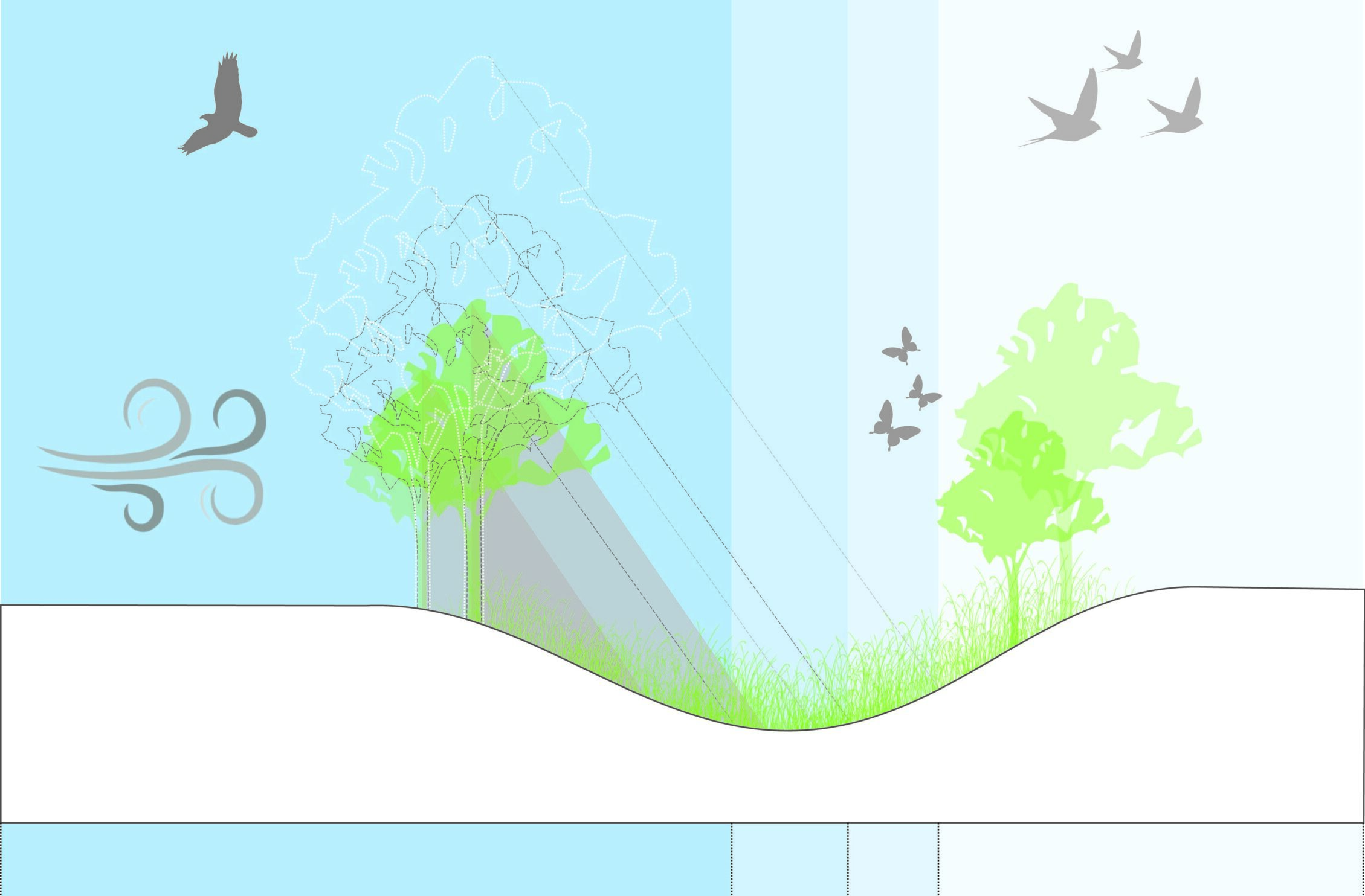
Shade tolerance and direct sunlight
The light requirements for each species are listed as ranges between full shade and full sun. At the bottom of the range—full shade—plants thrive in conditions where they receive filtered, or dappled, light for the entire day (such as under an oak tree). In the middle of the range are plants that grow best in partial shade, where they are in full shade for two to three hours during midday. Plants that require full sun should be sited so that they receive five or more hours of direct sun during the growing season. Some plants requiring full sun may still do well in a partial shade environment, depending on the quality and duration of the light the plants receive when they are not in shade.
Figure 4.13‑2: Micro-climate and landscape design from GSI Landscape Design Guidebook

Womrath Park Rain Garden Hydrologic zones
- For planting within a stormwater management practice (SMP), it is necessary to determine what hydrologic zones will be created within the SMP. Hydrologic zones describe the degree to which an area is inundated by water (the designer is referred to Figure 4.13‑3 for an example of hydrologic zones in a bioinfiltration/bioretention basin). Plants have differing tolerances to inundation and, as an aid to landscape designers, these plant tolerance levels have been divided into six zones and corresponding appropriate plant species have been identified. In Table I‑1 of Appendix I, each plant species has a corresponding hydrologic zone provided to indicate the most suitable planting location for successful establishment. While the most common zones for planting are listed in parentheses, the listing of additional zones indicates that a plant may survive over a broad range of hydrologic conditions. Just as plants may, on occasion, be found outside of their hardiness zone, they may also be found outside of their hydrologic zone. Additionally, hydrologic conditions in an SMP may fluctuate in unpredictable ways; thus, the use of plants capable of tolerating wide varieties of hydrologic conditions greatly increases a successful planting. Conversely, plants suited for specific hydrologic conditions may perish when hydrologic conditions fluctuate, thus exposing the soil and increasing the chance for erosion.
- Table I‑1, in addition to hydrologic zones, also includes drought tolerance and salt tolerance classifications. These parameters may also be used for vegetation selection for a site’s characteristics. The designer is referred to Appendix I for more information.
- The designer should also consider the entrance zone of the SMP. From page 34 of the GSI Landscape Design Guidebook, “The point where stormwater will be entering the SMP can be a difficult area for selecting plants. This zone is typically where there will be the highest velocity and volume of water entering as well as the highest concentration of sediment and pollutant loads. Therefore, selecting durable species that have strong structures and root systems is critical.”
Figure 4.13‑3: Hydrologic zones of a bioinfiltration/bioretention basin
The lowest zone (hydrologic zones 2–4) contains plant species adapted to standing and fluctuating water levels and frequent inundation. Frequently used native plants include the following species. The designer is referred to Table I‑1 in Appendix I for a complete listing.
Table 4.13‑1: Frequently used native plants for hydrologic zones 2–4
Frequently used native plants for hydrologic zones 2–4 asters (Aster spp.) winterberry (Ilex verticillata) goldenrods (Solidago spp.) arrowwood (Viburnum dentatum) bergamot (Monarda fistulosa) sweet pepperbush (Clethra alnifolia) blue-flag iris (Iris versicolor) bayberry (Myrica pensylvanica) sedges (Carex spp.) buttonbush (Cephalanthus occidentalis) ironweed (Vernonia noveboracensis) swamp azalea (Rhododendron viscosum) blue vervain (Verbena hastata) elderberry (Sambucus canadensis) joe-pye weed (Eupatorium spp.) red maple (Acer rubrum) swamp milkweed (Asclepias incarnata) river birch (Betula nigra) switchgrass (Panicum virgatum) sweetgum (Liquidambar styraciflua) shrub dogwoods (Cornus spp.) northern white cedar (Juniperus virginiana) The middle zone (hydrologic zones 4–5) is slightly drier than the lowest zone, but plants should still tolerate fluctuating water levels. Frequently used native plants include the following species. The designer is referred to Table I‑1 in Appendix I for a complete listing.
Table 4.13‑2: Frequently used native plants for hydrologic zones 4–5
Frequently used native plants for hydrologic zones 4–5 black snakeroot (Cimicifuga racemosa) spicebush (Lindera benzoin) switchgrass (Panicum virgatum) hackberry (Celtis occidentalis) spotted joe-pye weed (Eupatorium maculatum) willow oak (Quercus phellos) cutleaf coneflower (Rudabeckia lacinata) winterberry (Ilex verticillata) frosted hawthorn (Crataegus pruinosa) slippery elm (Ulmus rubra) marginal wood fern (Dryopteris marginalis) viburnums (Viburnum spp.) ironwood (Carpinus caroliniana) witch-hazel (Hamamelis virginiana) serviceberry (Amelanchier canadensis) steeplebush (Spiraea tomentosa) obedient plant (Physostegia virginiana) blueberry (Vaccinium spp.) The outer zone (hydrologic zones 5–6) generally supports plants adapted to drier conditions. Frequently used native plants include the following species. The designer is referred to Table I‑1 in Appendix I for a complete listing.
Table 4.13‑3: Frequently used native plants for hydrologic zones 5–6
Frequently used native plants for hydrologic zones 5–6 herbaceous plants juniper (Juniperus communis) basswood (Tilia americana) sweet-fern (Comptonia peregrina) white oak (Quercus alba) eastern red cedar (Juniperus virginiana) scarlet oak (Quercus coccinea) smooth serviceberry (Amelanchier laevis) black oak (Quercus velutina) American holly (Ilex opaca) American beech (Fagus grandifolia) sassafras (Sassafras albidum) black chokeberry (Aronia melanocarpa) white pine (Pinus strobus) Screening and aesthetics
- Some SMP elements such as chain link fences, concrete bulkheads, outfalls, riprap, berm embankments planted only with grasses, exposed pipe, banks, retaining walls greater than two feet high, and access roads are generally not aesthetically pleasing. When these elements face public right-of- ways or other private property, they should be screened with plant materials.
- The designer is strongly encouraged to integrate aesthetically pleasing landscape design into the SMP design.
4.13.3 Landscaping design considerations
The planting recommendations within this section are informed by research, local experience, and/or standard landscape industry methods for design and construction.
General planting design guidance
- Selected plant materials must be appropriate for soil, hydrologic, and other site conditions.
- Vegetated SMPs must use appropriate native and recommended non-invasive species from Appendix I.
- The design for planting should minimize the need for herbicides, fertilizers, pesticides, or soil amendments at any time before, during, and after construction and on a long-term basis.
- Plantings should be designed to minimize the need for mowing, pruning, and irrigation.
- Seed must be applied at the rates specified by the suppliers. If plant establishment cannot be achieved with seeding by the time of substantial completion of the SMP portion of the project, the contractor must plant the area with sod, plugs, container plants, or some other means to complete the specified plantings and protect against erosion.
- The designer may recommend a diversity of tree species and avoid overused species to reduce the risk of disease or insect infestation.
- The designer should avoid combinations of plants that will harm one another. For example, a designer should not plant junipers next to rust-susceptible plants like crabapples.
- The designer should consider the mature size of any plant and ensure that it has enough space to grow. The designer should also consider critical lines of sight for vehicular or pedestrian traffic.
- It is essential that impervious surfaces be graded toward the vegetated areas that are used as SMPs, and that these SMPs are depressed to allow for flow and/or surface ponding.
Quantity and spacing
Spacing of plant containers will depend on the plants’ characteristics. Smaller containers and plant varieties typically require tighter spacing than larger containers or larger mature growth. The designer is referred to the GSI Landscape Design Guidebook (page 19) for more assistance. Generally, six‑inch to twelve‑inch centers with triangular spacings for plugs are recommended.
Figure 4.13‑4: Recommended plant spacing
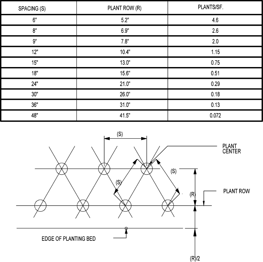
Mature canopy spread
The “Mature Canopy Spread” column of Table I‑1 in Appendix I gives the SMP designer a rough estimate of the diameter (or spread) of a tree species’ branching when it has matured. This information indicates what the light conditions will be like beneath the tree for understory plantings; how much space should be left open between the tree planting pit and any vertical structures, such as buildings; how far apart the trees should be planted; and it gives an idea, along with the mature height of the species, of the tree’s growth habit. The mature canopy spread also provides a rough idea for how much leaf surface area will be available to intercept stormwater before it reaches the ground.
Species selection and arrangement
- Existing native and non-native adapted vegetation should be preserved where possible.
- Noxious and invasive weeds must not be specified or used. The designer is referred to Table I‑2 in Appendix I for a list of native and recommended non-invasive plant species. Aggressive species should be used carefully to avoid spreading to other areas.
- Stream and water buffers should be planted with trees, shrubs, ornamental grasses, and herbaceous materials, where possible, to stabilize banks and provide shade. This will help to reduce thermal warming, reduce erosion, increase roughness, and protect habitat.
- Plantings that will require routine or intensive chemical applications (e.g., turf areas) should be avoided. Low-maintenance ground cover should be used as an alternative to turf.
- The designer should consider possible stressors (e.g., wind, exposure, exposure to runoff pollutants such as deicing salt, salt tolerance, insects, drought and inundation tolerance, and disease), micro-climates, and sunlight conditions when laying out the planting plan. If the planting plan includes overseeding, which is the process of laying seed atop existing vegetation without disturbing the soil, species appropriate for overseeding should be considered. The designer is referred to Table 4.13‑4 below for a list of species appropriate for overseeding. Overseeding can be beneficial for initial plant establishment, improving the plant density and coverage, and introducing new varieties to existing landscaping.
- Aesthetics and visual characteristics should be a prime consideration when developing planting plans. Plant form, texture, color, bloom time, and fragrance are important to the overall feel of the site. Plants can be used to enhance and frame desirable views or screen undesirable views. Care should be taken to not block views at entrances, exits, or along difficult road curves.
- The time of year when the site will be most active should be considered to decide which season to emphasize most prominently. The designer may choose to use flowering perennials as accents that will bloom throughout the growing season and include shrubs with interesting winter structure to showcase during the dormant season. Some characteristics the designer should keep in mind are evergreen needles, fall foliage color, seasonal fruits and flowers, bark texture, and leaf color. The designer is referred to the GSI Landscape Design Guidebook for more information.
- Where such conditions exist, trees and shrubs should be placed in a manner that restricts pedestrian access to steep pools or slopes without blocking maintenance access.
- Existing and proposed utilities must be identified and considered.
- Other considerations for designers for plant selection and arrangement are planting in massings, an appropriate number of species, enhancing habitat, defining an edge, plant height, site lines, and other site contexts. The designer is referred to pages 20 through 27 of the GSI Landscape Design Guidebook for more information.
Table 4.13‑4: Species appropriate for overseeding
Species appropriate for overseeding Aquilegia canadensis Columbine Andropogon ternarius Splitbeard Bluestem Bouteloua curtipendula Side Oats Gramma Coreopsis grandiflora Large-Flowered Tickseed Coreopsis lanceolata Lanceleaf Coreopsis Gaillardia pulchella Indian Blanket Monarda sp. — Penstemon sp. — Schizachyrium scoparium Little Bluestem Sporobolus asper Tall Dropseed Figure 4.13‑5: Plant seasonality from the GSI Landscape Design Guidebook
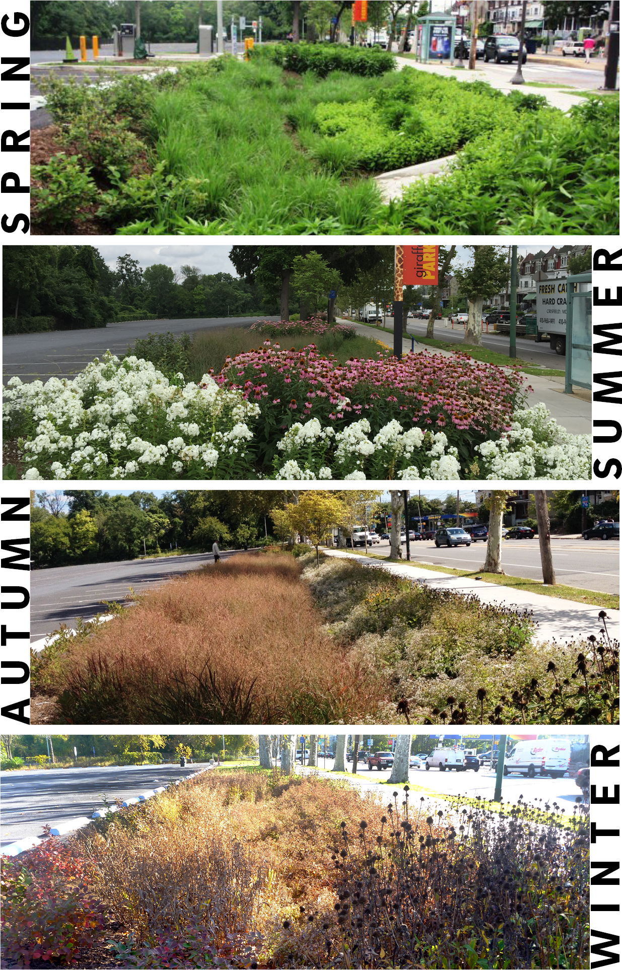
Philadelphia Zoo – Plantings selected provide interest during all seasons along a busy corridor. Plant nativity
- A native plant is any indigenous species that subsisted in the region prior to settlement by Europeans. Each species within the “Nativity” column of Table I‑1 in Appendix I is located within a range of nativity to Philadelphia. Plants known to have existed in Philadelphia County are native to Philadelphia, while a wider geographic range lists plants native to the state, but not necessarily to the county. The widest geographic range lists a few species native to the United States, though not necessarily to Pennsylvania. The plants listed that are not specifically native to Philadelphia are included because of their demonstrated success within SMPs.
- Invasive plants reproduce rapidly, degrade, and take over natural ecosystems. Under no circumstance should they be planted in a SMP. Because of appealing characteristics, some of these plants are available for sale, and care should be taken not to purchase them. Additionally, the ability to identify and remove them before they can establish themselves is important, as they almost always invade due to their gregarious reproductive strategies. They can be especially hard to eradicate once they take hold. The designer is referred to Table I‑2 in Appendix I for a list of species to avoid.
Embankments, spillways, and dams
- Planting trees, shrubs, and/or any type of woody vegetation is not allowed on structural embankments.
- All emergency spillways should be stabilized with plant material that can withstand strong flows. Root material should be fibrous and substantial but lack a taproot.
- Trees or shrubs known to have long taproots should not be planted within the vicinity of an earthen dam or subsurface drainage facilities.
- Trees and shrubs should be planted at least 25 feet away from a principal spillway structure and at least 15 feet away from a dam’s toe of slope.
Mulch and soil media
- The mulch layer helps maintain soil moisture and avoid surface sealing that reduces permeability. Mulch helps prevent erosion and provides a micro-environment suitable for soil biota at the mulch/soil interface. It also serves as a pretreatment layer, trapping the finer sediments that remain suspended after the primary pretreatment.
- For herbaceous plantings, mulch must be applied to cover all soil between plants.
- Care should be exercised to use the appropriate amount of mulch—any more than three to four inches can negatively impact growing conditions and cause excessive nutrients to leach into the SMP.
- Mulch must be weed-free. Manure mulching and high-fertilizer hydroseeding are prohibited in a SMP area during and after construction.
- Mulch should be kept three inches away from tree trunks, woody vegetation, and the base of herbaceous vegetation.
- Permanent irrigation systems are allowed, but the designer is encouraged to minimize the need for permanent irrigation. Innovative methods for watering vegetation are encouraged, such as the use of cisterns and air conditioning condensate.
- To ensure landscape plant survival and overall stormwater facility functional success, the design and construction documents must include elements that help achieve these results.
- The characteristics of the soil for the bioinfiltration/bioretention SMP are arguably as important as the facility location, size, and treatment volume. The soil must be permeable enough to allow runoff to filter through the media, while having characteristics suitable to promote and sustain a robust vegetative cover crop. In addition, much of the nutrient pollutant uptake (nitrogen and phosphorus) is accomplished through adsorption and microbial activity within the soil profile. Therefore, the soils must balance soil chemistry and physical properties to support biotic communities above and below ground.
4.13.4 Landscaping material standards
Landscaping relies on informed design and material standards for successful landscapes. Designers should consider the following material guidance for selecting and sourcing materials for the site.
Storage area material standards
- Stone designed for stormwater storage must be uniformly graded, crushed, clean-washed stone. PWD defines “clean-washed” as having less than 0.5% wash loss, by mass, when tested per American Association of State Highway and Transportation Officials (AASHTO) T-11 wash loss test. AASHTO No. 3 and No. 57 stone can meet this specification.
- Sand, if used, must be AASHTO M‑6 or American Society of Testing and Materials (ASTM) C‑33 sand and must have a grain size of 0.02 to 0.04 inches.
- Planting soil medium
- Planting soil should meet all the specifications listed below and should be a fertile, natural soil, free from large stones, roots, sticks, clods, plants, peat, sod, pockets of coarse sand, pavement and building debris, glass, noxious weeds including invasive species, infestations of undesirable organisms and disease-causing pathogens, and other extraneous materials harmful to plant growth.
- The texture of planting soil should conform to the classification within the United States Department of Agriculture triangle for Sandy Loam or Loamy Sand. Planting soil should be a mixture of sand, silt, and clay particles as required to meet the classification. Ranges of particle size distribution, as determined by pipette method in compliance with ASTM F-1632, are as follows:
- Sand (0.05 to 2.0 mm): 50 – 85%
- Silt (0.002 to 0.05mm): 40% maximum
- Clay (less than 0.002mm): 10% maximum
- Gravel (2.0 to 12.7 mm): 15% maximum
- Planting soil should be screened and free of stones larger than a half‑inch (12.7 millimeters) in any dimension. No more than 10% of the soil volume should be composed of soil peds greater than one inch.
- Clods, or natural clumps of soils, greater than three inches in any dimension should be absent from the planting soil. Small clods ranging from one to three inches and peds, natural soil clumps under one inch in any dimension, may be present but should not make up more than 10% of the soil by volume.
- The pH of the planting soil should have a range of 5.8 to 7.1.
- Soluble salts should be less than 2.0 mmhos/cm (dS/m), typically as measured by 1:2 soil-water ratio basic soil salinity testing. Sodic soils (Exchangeable Sodium Percentage greater than 15 and/or Sodium Adsorption Ratio greater than 13) are not acceptable for use, regardless of amendment.
- Organic content of planting soil should have a range of 3% to 15% by weight, as determined by loss on ignition (ASTM D2974). To adjust organic content, planting soil may be amended, prior to placing and final grading, with the addition of organic compost.
- Mulch, if used, must be free of weeds and must consist of aged, double-shredded hardwood bark mulch or leaf mulch that has been shredded sufficiently to limit risk of matting, which can limit surface infiltration rates. For hydroseeding, paper mulch may be used. Approved mulching materials include organic materials such as compost, bark mulch, leaves, as well as small river gravel, pumice, or other inert materials. Grass clippings should not be used as mulch.
- Geotextile must consist of polypropylene fibers and meet the following specifications (AASHTO Class 1 or Class 2 geotextile is recommended):
- Grab Tensile Strength (ASTM-D4632): ≥ 250 lbs
- CBR Puncture Strength (ASTM-D6241): ≥ 500 lbs
- Flow Rate (ASTM-D4491): ≥ 95 gal/min/ft2
- UV Resistance after 500 hours (ASTM-D4355): ≥ 70%
- Tear Resistance (ASTM-D4533): ≥ 80 lbs
- Heat-set or heat-calendared fabrics are not permitted.
Vegetation material standards
- Trees and shrubs must be freshly dug and grown in accordance with good nursery practice.
- Perennials and herbaceous plants must be healthy, well-rooted specimens.
- A native grass/wildflower seed mix can be used as an alternative to groundcover planting. Seed mix must be free of weed seeds.
- Use of invasive plants is not permitted. All plants and trees must be appropriate and compatible with soil, hydrologic, light, and other site conditions. Biodiversity should also be considered. The designer is referred to Appendix I for plant lists.
- SMP soils should provide adequate infiltration rates and be suitable for healthy tree and vegetation growth. Soil analysis must be conducted within the SMP area to determine appropriate levels and types of soil amendments. The designer is referred to Section 3.3.6, Evaluation of Infiltration Testing Results, for additional guidance and requirements for soil amendment installation.
- If topsoil exists on-site and is stockpiled for re
–use, appropriate erosion control measures, as required by the latest edition of the PA DEP Erosion and Sediment Pollution Control Program Manual, must be used.
4.13.5 Landscaping construction guidance
Careful consideration of issues like soil compaction, infiltration performance, and sediment control are critical to ensure proper vegetated SMP functionality and reduce long-term maintenance needs. Poor oversight of construction activities could result in the need for substantial reconstruction to address performance problems.
General landscaping sequence
- Provide erosion and sedimentation control protection on the site such that construction runoff is directed away from the proposed vegetated SMP location. The designer is referred to the latest edition of the PA DEP Erosion and Sediment Pollution Control Program Manual for information on design standards for erosion and sedimentation control practices.
- Critical areas, including vegetated SMPs, must be physically marked prior to any land disturbance activities to avoid soil disturbance and compaction during construction. Install construction fencing around these critical areas.
- After allowing for settlement, complete final grading within about two inches of the proposed design elevations, leaving space for top dressing of mulch or mulch/compost blend.
- Seed and plant vegetation as indicated on the plans and specifications.
- Place mulch and hand grade to final elevations.
- Water vegetation at the end of each day for two weeks after planting is completed.
- Water vegetation regularly during first year to ensure successful establishment.
Establishment and stabilization
- Establishment procedures must include control of invasive weeds, prevention of damage from animals and vandals, use of erosion control mats and fabrics in channels, temporary diversion of flows from seeded areas until stabilized, mulching, re-staking, watering, and mesh or tube protection replacement, to the extent needed to ensure plant survival.
- Generally, there are two planting seasons in a calendar year; Spring begins in March and ends in May, and Fall begins in September and ends in November, but planting is temperature dependent and varies year to year.
- Unwanted vegetation in the SMP area should be removed during site preparation with equipment appropriate for the type of material encountered, and site conditions. It is recommended that the maximum amount of pre-existing native vegetation be retained and protected.
- No material storage or heavy equipment is allowed within the SMP area after site clearing and grading has been completed, except to excavate and grade, as needed, to build the SMP. No compaction of infiltration areas must occur during this excavation.
- After the SMP area is cleared and graded, any necessary soil amendments should be added and tilled into the existing soil to the depth specified for each SMP. No tilling should occur within the drip line of existing trees. After tilling is complete, no other construction traffic must be allowed in the area, except for planting and related work. Where topsoil is needed, it should be spread to a depth of four to eight inches and lightly compacted to a minimum thickness of four inches—this provides organic matter and important nutrients for the plant material. The use of topsoil allows vegetation to become established faster and roots to penetrate deeper. This ensures quicker and more complete stabilization, making it less likely that the plants will wash out during a heavy storm.
- Newly installed plant material requires water in order to recover from the shock of being transplanted. A source of water should be provided during establishment of the SMP, especially during dry periods. This will reduce plant loss and provide the new plant materials with a chance to establish root growth.
- Establishment procedures must be applied temporarily (typically ranges from 8 weeks to 2 years). These measures include control of invasive weeds, prevention of damage from animals and vandals, the use of erosion control mats and fabrics in channels, temporary diversion of flows from seeded areas until stabilized, mulching, re-staking, watering, and mesh or tube protection replacement, to the extent needed to ensure plant survival.
- To ensure landscape plant survival and overall stormwater facility functional success, the design and construction documents must include elements that help achieve these results.
- Construction specifications and details must include staking, irrigation schedule, soil amendments, plant protection, overplanting, and potentially, mycorrhizal inoculation.
Table 4.13‑5: Planting construction specifications
Specification element Elements Sequence of construction Describe site preparation activities, soil amendments, etc.; address erosion and sediment control procedures; specify step-by-step procedure for plant installation through site clean-up. Contractor’s responsibilities Specify the contractors’ responsibilities, such as watering, care of plant material during transport, timeliness of installation, repairs due to vandalism, etc. Planting schedule and specifications Specify the materials to be installed, the type of materials (e.g., B&B, bare root, containerized); time of year of installations, sequence of installation of types of plants; fertilization, stabilization seeding, if required; watering and general care. Maintenance Specify inspection periods; mulching frequency (annual mulching is most common); removal and replacement of dead and diseased vegetation; treatment of diseased trees; watering amount and schedule after initial installation (once per day for 14 days is common); repair and replacement of staking and wires. Warranty All systems should contain a two‑year warranty. Specifications should contain the warranty period, the required survival rate, and expected condition of plant species at the end of the warranty period. 4.13.6 Landscaping maintenance guidance
Vegetation maintenance is design-specific with the plants, grading, SMP layout, as well as external factors all influencing the types and frequencies of activities required to keep vegetated SMP functioning properly. The designer should consider maintenance when evaluating the different variables associated with landscape design. The designer is referred to pages 30 and 31 of the GSI Landscape Design Guidebook for landscaping recommendations, in addition to the below guidance.
Maintenance considerations
- The designer should carefully consider the long-term vegetation management strategy for the SMP, keeping in mind the maintenance legacy for the future owners. The O&M Agreement will include requirements to ensure vegetation cover in perpetuity.
- When appropriate, the designer should provide signage to help educate the public about SMPs and designate limits of mowing (wildflower areas, meadows, etc.).
- The edge of the basin may be designated by woody vegetation to further designate limits of mowing and foot traffic.
- Planting in massings (each group consisting of one to three individuals of the same species) may support maintenance efforts by simplifying plant identification.
Maintenance activities
General recommended maintenance activities for landscaped areas are summarized in Table 4.13‑6 below. More comprehensive maintenance guidance, including means and methods of various landscaping related maintenance activities like weeding, mowing, mulching, watering, and pest and disease management, are available in the GSI Maintenance Manual.
Table 4.13‑6: Landscaping maintenance guidelines
Early maintenance activity Frequency Water vegetation at the end of each day for two weeks after planting is completed. Daily for two weeks after installation Water vegetation regularly to ensure successful establishment. Every four days during periods of four or more days without rain, June through August for the first year after installation Inspect vegetation for signs of disease or distress. Biweekly for the first year after installation Inspect inlet controls, outlet structures, and storage areas for trash and sediment accumulation. Monthly for the first year after installation to determine ongoing maintenance frequency Ongoing maintenance activity Frequency Remulch bare areas. As needed Treat diseased trees and shrubs. As needed Keep overflow free and clear of leaves. As needed Inspect soil and repair eroded areas. Monthly Remove litter and debris. Monthly Clear leaves and debris from overflow. Monthly Inspect trees and shrubs to evaluate health, replacing if necessary. Quarterly Inspect underdrain cleanouts. Quarterly Add additional mulch. Quarterly Inspect for sediment build-up, erosion, and vegetative conditions. Quarterly Evaluate the drain down time of the SMP after a storm of at least one inch within no more than 24‑hours to ensure an SMP drain down time of less than 72 hours. Ongoing Maintain records of all inspections and maintenance activity. Ongoing The designer is referred to Section 4.1, Bioinfiltration/Bioretention, Section 4.3, Green Roofs, Section 4.14, Blue-Green Roofs, Section 4.7, Ponds and Wet Basins, Section 4.9, Media Filters, Section 4.10, Pretreatment, Section 4.11, Inlet Controls, and Section 4.12, Outlet Controls, for information on maintenance guidance for specific SMP types, pretreatment, inlet controls, and outlet controls.
-
4.14 Blue-Green Roofs
Download summaries of this SMP and its maintenance guidance, with quick reference information for clients and developers:
4.14.1 Blue‑green roof introduction
Blue‑green roofs are a hybrid system consisting of a green roof (moisture-interception layer/geotextile, drainage layer, engineered growing medium, and vegetation above the roofing system and its waterproofing membrane) and a blue roof, a portion of the roof that will become flooded during storm events to aid in the retention of runoff to be used by the green roof vegetation.
Blue‑green roofs provide the combined benefit of the detention and slow-release function of a blue roof with the contaminant removal function of a green roof. The key advantage of the blue‑green roof compared to the green roof is that the maximum tributary area can be potentially increased with the use of an outlet control component designed to meet PWD’s rate of discharge and drain down time requirements.
The design of blue‑green roofs is not limited to the design parameters presented within this text, which focuses on a minimum media depth with a roof drain restrictor system designed to retain water and to meet the maximum Water Quality discharge rates. The designer is referred to Section 4.12 for information on outlet controls.
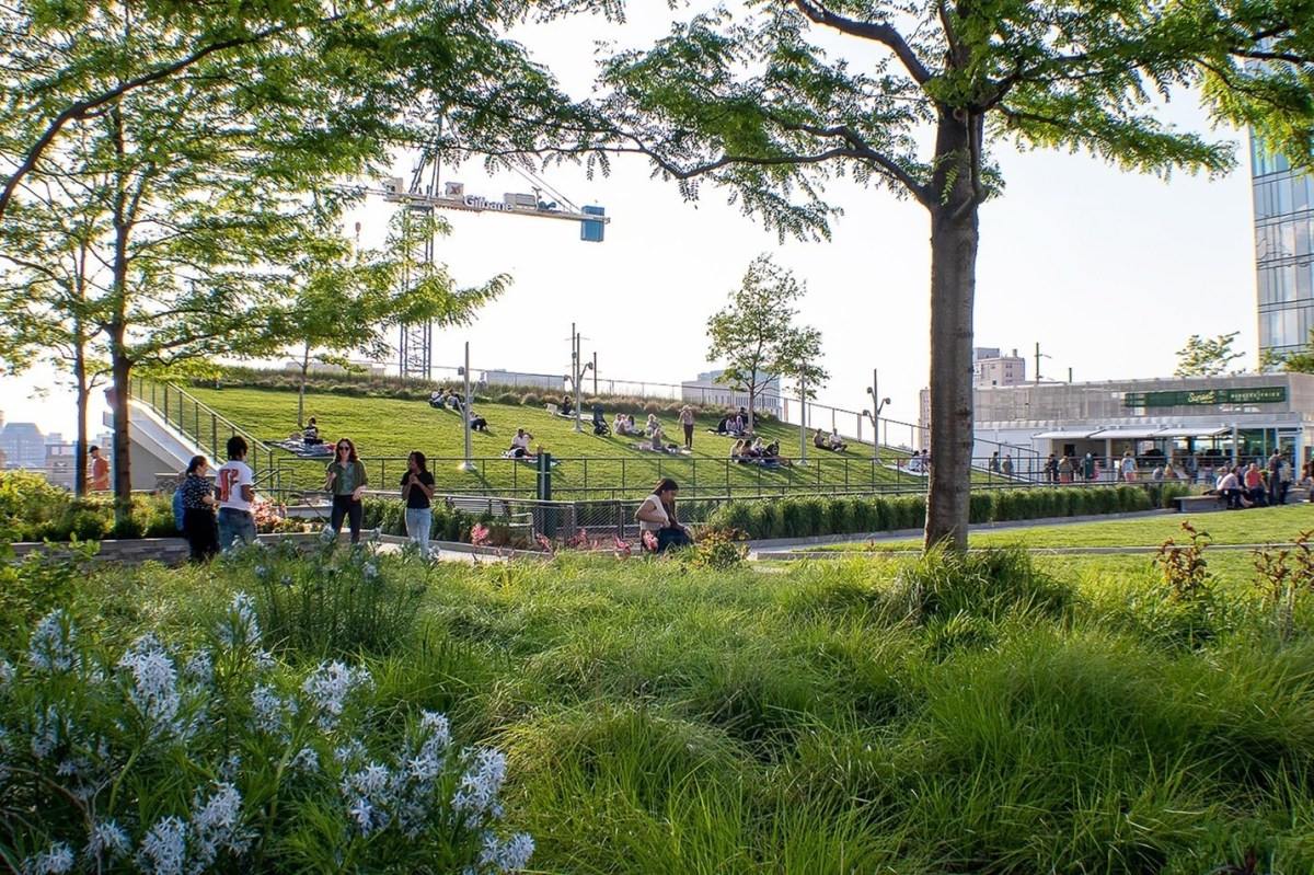
An example of a blue‑green roof in Philadelphia Where can blue‑green roofs be used?
A blue‑green roof can be considered for installation on a fully built-out or highly constrained site. They can be installed on many types of roofs, including terraces, high-rise building roofs, and low-podium or at-grade on-structure installations. Generally, blue‑green roofs are more appropriate for roofs with mild pitches (0–2%), due to structural loading considerations.
Blue‑green roofs can also be installed as a Stormwater Retrofit on existing buildings with flat, mildly sloped, or terraced roofs after confirmation of adequate structural loading capacity, waterproofing, and protection of rooftop utilities.
Key advantages of blue‑green roofs
- Manage stormwater runoff without occupying surface-level space
- Well-suited for sites where roofs make up a large portion of the total impervious area and for sites with ground-level space constraints
- Require no minimum flow path of runoff across the green roof surface since runoff is restricted at the outfall
- Typically require no additional sewer connections besides those already provided for the building
- Promote the retention, slow release, and evapotranspiration of precipitation
- Enhance building aesthetics and market value
- Help regulate building temperature in both the summer and winter, thus reducing cooling and heating costs
- Reduce urban heat island effect by providing evaporative cooling
- Can improve air quality by filtering particulate matter
- Extend the service life of the roof by protecting the underlying roof membrane from mechanical damage, shielding it from UV radiation, and buffering temperature extremes
- Require no excavation
- Can be designed to provide spaces for recreation, supplement bird habitat, develop educational resources, and create new opportunities for urban food production
- Can provide educational benefits, especially when used at public and/or highly visible sites such as schools, recreation centers, libraries, etc.
- Assume less risk for projects within the floodplain
- Eligible for inclusion in an Expedited Post‑Construction Stormwater Management Plan (PCSMP) Review project
Key limitations of blue‑green roofs
- May need to be combined with other SMPs to meet the Flood Control requirement
- More expensive to install than most conventional roofs
- May result in increased cost or limited Stormwater Retrofit opportunities for existing buildings and structures due to additional loading associated with ponded water on roof
- May have limited Stormwater Retrofit feasibility for existing buildings and structures due to structural loading limitations
Key design considerations for blue‑green roofs
- Blue‑green roof systems utilizing controlled flow roof drains generally require flat or nearly flat roofs (e.g., less than 2% slope). It may be feasible to use check dams when slopes are higher than 2%.
- Stormwater management can be improved by introducing measures to enhance evapotranspiration. Measures may include:
- Introducing low-transmissivity drainage layers;
- Lengthening seepage pathways to drains;
- Introducing rainfall interception layers;
- Selecting plants with dense root habits; and
- Selecting growing medium with high water-holding capacity.
- Plant density and coverage are more significant for stormwater performance than specific species type (note that species selections remain important from a habitat and ecosystems perspective). Long-term species selection is flexible provided the plant cover is continuous, the root masses are persistent, and:
- Blue‑green roofs should include a significant percentage of evergreen plants to minimize erosion in winter months.
- For stormwater management purposes, artificial or synthetic turf roofs are not considered green roofs and must be combined with other SMPs.
- For any blue‑green roof that discharges onto an adjacent property, a drainage easement is required.
- Building mechanical systems, roof furniture, and other appurtenances installed on the roof should not be compromised by roof ponding during rain events and must not cause damage to the roof membrane.
- Coordination of blue‑green roof design with the design of building heating, ventilation, and air conditioning (HVAC) systems can help to maximize operational cost savings. For example, some research suggests that green roofs can improve building energy efficiency by lowering the temperature of air at the intakes for climate control systems.
Blue‑green roof types
The blue‑green roof includes a type of green roof combined with a roof drain restrictor system used to retain water in the base of the profile for subsequent plant transpiration, with eventual discharge to the roof drain. The designer is referred to Section 4.3.1 for green roof types.
4.14.2: Blue‑green roof components
Figure 4.14‑1: Partially paved blue‑green roof with typical features
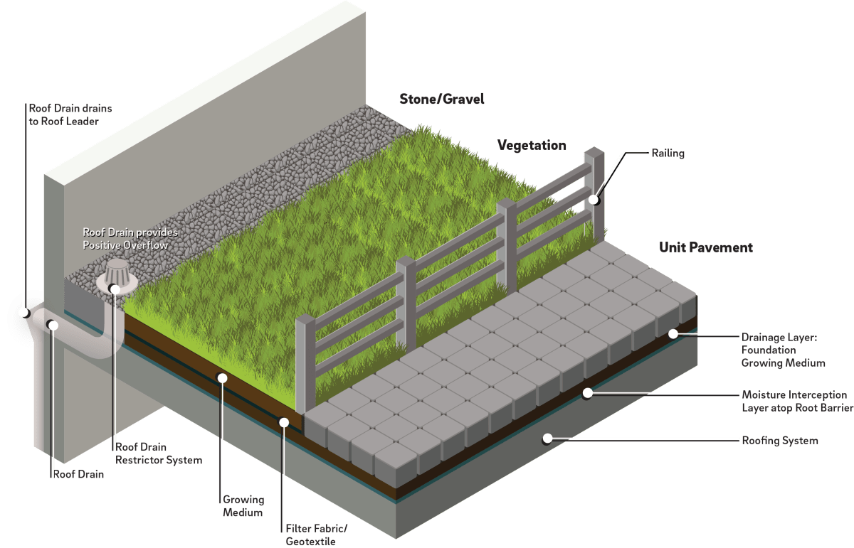
Inlet control component
For blue‑green roofs that receive runoff from roof directly connected impervious area (DCIA), inlet control systems may convey and control the flow of stormwater from the contributing catchment area to the blue‑green roof. Distribution piping may be used to evenly disperse run-on water throughout the blue‑green roof. The designer is referred to Section 4.11, Inlet Controls, for more information on inlet controls.
Storage area component
Blue‑green roof storage areas temporarily hold stormwater before it can either be used by plants through evapotranspiration or be released downstream at a controlled rate. Storage areas for green roofs typically are composed of the following components:
The growing medium supports plant growth and provides for storage of stormwater within voids. The storage capacity is a function of medium depth, surface area, and total void space. The total growing medium depth includes, as applicable, the primary growing medium, root-friendly moisture retention products, and root-friendly drainage aggregates such as foundation growing medium (lightweight drainage aggregate) as a base. Storage in roof drain restrictor systems is determined by the roof slope and geometry relative to both the height of the restrictor and the depth of the growing medium.
Filter fabric, also called separation fabric, or geotextile, prevents migration of soil into the underlying drainage layer of the green roof.
A drainage layer may incorporate measures to intercept and retain percolated rainfall as it moves through the green roof storage area. Examples include synthetic sheets with waffle-type cups to hold water and specialized fabrics or mats with high capillary indices. Drainage products that have low horizontal flow rates and allow deep growth of plant roots are required for green roofs managing runoff from adjacent tributary surfaces. Root-friendly drainage products include foundation growing medium (lightweight drainage aggregates) and waffled reservoir sheets where the cups are filled with lightweight aggregate.
Moisture interception layers are thick geotextiles or other porous materials that retain water and help protect the underlying roof deck. Moisture interception layers can help increase moisture availability to plants between rain events.
Root barriers are impermeable liners or membranes that protect the underlying roof deck from moisture and plant root intrusion. Similar to blue roof storage, blue‑green storage areas are underlain by a waterproofing membrane. Some waterproofing membrane materials are inherently root resistant, whereas others require an additional root barrier.
Numerous waterproofing membrane systems are commonly available, including modified bitumen roofing (MBR), waterproof types of single-ply roofing, metal roof panels, spray polyurethane foam roofing, synthetic rubber membranes, thermoplastic membranes, and liquid-applied (including polyurethane-based and polymer-modified bituminous products) roofing. While high quality MBR systems (multiple MBR sheets tiled to reduce seam susceptibility) are suitable for blue roof usage, lower quality MBR systems (multiple layers of asphaltic sheets) are not recommended due to their seams that allow water to penetrate.
Underlying roofing systems typically consist of a structural deck, its supporting structures, and a traditional overlying waterproofing system. Because of their durability and lack of seams, a hot fluid applied, rubberized asphalt, fabric reinforced roofing system is well-suited for blue‑green roofs. Cold liquid-applied systems are equally effective due to strict regulations on the use of the propane-fired devices for hot fluid systems.
Vegetation component
Blue‑green roof plant material is designed to take up much of the water that falls on the roof during a storm event. Plant cover is instrumental in controlling wind erosion of the underlying blue‑green roof materials. It mitigates soil moisture loss and water erosion, transpires captured moisture back into the atmosphere, and provides evaporative cooling. Plant material also collects dust and creates oxygen. Some blue‑green roofs may also have irrigation systems to support plant growth during dry periods.
Outlet control component
Outlet controls within a blue‑green roof system can provide a range of functions, including the following:
- Meeting drain down time requirements;
- Controlling the rate of discharge from the SMP and limiting water surface elevations during various storm events; and/or
- Bypassing of flows from large storm events.
Outlet controls may include orifices, weirs, roof drain restrictors, risers, scuppers, impervious liners, micro siphon drain belts, and/or low flow devices. The designer is referred to Section 4.12, Outlet Controls, for more information.
Roof drain restrictor blue‑green roofs use a roof drain restrictor that is placed over the roof drain. These devices restrict flow through an outlet control within the drain assembly, causing temporary ponding on the roof. They may be purchased commercially through a manufacturer, or a manufacturer can customize an outlet control sized for a specific development. The number and sizing of weirs and orifices are based on a predetermined relationship between the water depth approaching the drain and the flow rate entering the drain. The overflow mechanism of the device determines the maximum ponding depth.
Micro siphon drain belts are drainage systems that use capillary pressure to wick water out of the soil or filter media and convey it through small siphon channels to collector drainpipes. Their application within a blue‑green roof allows for the collection of stormwater over a large surface area and for meeting very low release rate requirements. Micro siphon drain belts must connect to a downslope collector pipe or roof drain, and they may be installed in the foundation growing medium layer. The designer is referred to Section 4.12.8 for more information on designing micro siphon drain belt systems within a blue‑green roof.
Paving component
Paved walkways, stepping stones, patios, and paver or stone perimeter strips are common elements of blue‑green roof designs. Non-vegetated surfaces that discharge runoff into the vegetated area of the blue‑green roof must count toward the impervious runoff loading ratio.
Inspection and maintenance access component
Safe and easy inspection and maintenance access to all major components within a blue‑green roof is critical to ensuring long-term performance. Dependent on roof height and slope, blue‑green roof inspection and maintenance access components may consist of permanent or temporary safety monitoring systems, guardrail and safety net systems, warning line systems, and/or personal fall arrest systems. Inspection and maintenance access systems for blue‑green roofs may also include long-term leak detection systems for locating and managing leaks.
In the case of accessible roof terraces for residential settings, the provision of a railing with a maintenance gate that separates the vegetated green roof from accessible areas is required. The railing can be metal, wood, or glass. Bird-friendly glass with a Threat Factor Rating of 1–25 is highly recommended. Pet access to green roofs that are certified as SMPs should be restricted, as urine, pet digging, and habitual foot traffic can all damage plants and growing medium, leading to potential erosion and diminished rainfall management performance.
4.14.3 Blue‑green roof design standards
General design standards
- Structural requirements:
- Structural loading must be considered for all blue‑green roof designs, and blue‑green roof design must be coordinated with a licensed structural engineer for both new building construction and retrofits to existing structures.
- A structural engineer must verify that the building will support the weight of the blue‑green roof.
- Design calculations must consider the fully saturated media and flooded storage weight of the blue‑green roof. Due to their water holding capacity, blue‑green roofs typically weigh more than 45 pounds per square foot and are most common in new construction where the roofing design can accommodate these loads.
- Potential maximum loads must be based on American Society of Testing and Materials (ASTM) E2397.
- The entirety of the blue‑green roof footprint must be considered, and modeled as, DCIA. Accordingly, a Natural Resources Conservation Service curve number of 98 must be used for the blue‑green roof, where required for hydrologic calculations.
- Vegetated green roof portions of the blue‑green roof are permitted a DCIA reduction equal to the entire area of the vegetated footprint solely for the predevelopment to post-development impervious area reduction calculation during the determination of potential exemption from the Channel Protection and Flood Control requirements.
- The total impervious roof area within the designated boundary of a blue‑green roof footprint must not exceed the total vegetated green roof area, which is equivalent to a maximum hydraulic impervious runoff loading ratio of 1:1.
- The following are exempt from being counted as tributary impervious area when installed on a blue‑green roof:
- Pervious pavers containing planted openings; and
- Drain chambers, including an adjacent stone margin with an offset distance from the chamber edge of 12 inches or less. All other stone/gravel margins or perimeters must be considered roof DCIA, unless they are graded to allow flow over or through vegetated green roof area, in which case, they may be counted as tributary impervious area to the green roof portion of the blue‑green roof.
- The maximum allowable ponding depth is one inch below the top of the foundation growing medium. For roof drain restrictor systems, this ponding depth maximum can be set at least five feet from the restrictor.
- The maximum allowable drain down time is 72 hours after the 24‑hour storm event.
- Positive overflow must be provided and comply with the Philadelphia Plumbing Code
- The flooded storage area of the blue‑green roof area must be underlain by a waterproofing membrane.
- Root barrier layers must conform to the requirements of the waterproofing provider for each project.
Inlet control design standards
- If runoff is conveyed via piping, a distribution piping manifold must be embedded in a gravel strip to dissipate energy and promote uniform flow. The designer is referred to Section 3.4.2 for information on design standards for distribution piping.
- The designer is referred to Section 4.11 for information on design standards for inlet control systems.
Storage area design standards
- For roof drain restrictor blue‑green roofs that rely solely on growing medium to retain the Water Quality Volume (WQv):
- The minimum allowable thickness of the green roof growing medium for a 1:1 loading ratio is six inches, including two inches of foundation growing medium, which serves as the drainage layer.
- Any contributing impervious surface built atop a blue‑green roof must either allow for sheet flow runoff onto the vegetated portion of the roof, like unit pavement, or be slotted, like decking. The minimum two‑inch thickness of foundation growing medium required for the blue‑green roof must extend under the entire extent of that surface area.
- The top one inch of the foundation growing medium must be maintained above the flooded elevation, starting five feet from the roof drain restrictor, to promote aerated conditions in the growing medium.
- The roof drain restrictor must include an outfall device which limits the WQv discharge flow rate to comply with applicable Water Quality requirements.
- In areas that will receive tributary discharge, the blue‑green roof must not include a high-transmissivity drainage layer, defined as a layer with a transmissivity of greater than 0.005 m2/s (ASTM D4716), where such products limit plant root access to tributary runoff. In general, this will exclude most synthetic sheet drains, including peg-style or egg carton style drains. High-transmissivity drainage layers will allow runoff to effectively flow under the blue‑green roof, minimizing contact with growing medium and plant roots. Typical foundation growing medium (also called granular aggregate or coarse granular green roof medium), with a grain-size distribution complying with ASTM gradation No. 7 will satisfy the requirement, as will also a variety of mats and composite drainage layer assemblies.
- The storage system must provide adequate storage to control release rates to meet all applicable Stormwater Regulations. The designer is referred to Section 3.2.3 for information on using SMPs in series.
- Saturated permeability of the growing medium, in its compacted state [ASTM E2399], must not be less than six inches per hour.
- Filter or separation fabric must allow root penetration but prevent the growing medium from passing through into the drainage layer.
- A drainage layer is required to promote aerated conditions in the growing medium and to convey excess runoff during large rainfall events.
Vegetation design standards
- When fully established, the selected plantings must thoroughly cover the growing medium. Mature plant cover must be a minimum of 80% on established green roofs, with contiguous non-vegetated areas no larger than three square feet (i.e., a 24‑inch diameter circle).
- Plant coverage must persist year-round. While individual plants may exhibit seasonal dormancy, vegetation coverage in winter months must be maintained. Mulch should be limited to 0.25 inches of compost if used as a temporary component in an establishment planting. Mulching can jeopardize green roof performance by clogging the geotextiles within the system and increasing system weights. Mulching also inhibits the reseeding of plants, which is a necessary process for long-term species persistence.
- Plants that are appropriate for, and compatible with, the site conditions must be chosen. The designer is referred to Section 4.13 for additional landscaping guidance and Appendix I for plant lists.
Outlet control design standards
- The contributing drainage area of impervious rooftop to each disconnected discharge point must be equal to, or less than, 500 square feet.
- Roof drain restrictors must be sized according to the desired release rate and ponding depth.
- Internal drainage, including provisions that cover and protect drains or scuppers, must anticipate the need to manage large rainfall events without inundating the cover.
- All drains and scuppers must be covered and protected by an enclosure, typically a square or round chamber with a locking lid. These chambers are designed to prevent clogging of the drains by debris.
- The roof drainage system and the remainder of the site drainage system must safely convey roof runoff to the storm sewer, combined sewer, or receiving water.
- Emergency outflow must be set at an elevation above the height of the roof drain restrictor.
- The designer is referred to Section 4.12 for information on design standards for outlet control systems.
Inspection and maintenance access design standards
- Blue‑green roofs must be designed to allow for safe access and working conditions for green roof inspection and maintenance personnel. This access must be a permanent feature of the building, such as a pilot house, roof hatch, or exterior stairs to the blue‑green roof. Retractable, unsecured ladders should not be required for routine maintenance and inspections due to safety concerns. The design may include other permanent personal safety measures. For blue‑green roofs, designers must specifically assess applicability to Occupational Safety and Health Administration (OSHA) Fall Protection Safety Standards and the American National Standards Institute (ANSI) and American Society of Safety Engineers (ASSE) consensus-based fall protection standards.
- Easy access must be provided to each of the outlet controls, low flow discharge points, and overflow connections to permit removal of debris under saturated conditions.
- Seams, corners, penetrations, mounts, or platforms for mechanical utilities, and any other areas of the roofing membrane where risk of leakage is highest, must be inspected for damage or failure and repaired in a manner consistent with the membrane material.
- For accessible residential roof terraces, a railing with a maintenance gate that separates the vegetated green roof from accessible areas must be provided. The railing can be metal, wood, or glass. Bird-friendly glass with a Threat Factor Rating of 1–25 is highly recommended.
Figure 4.14‑2: Blue‑green roof standard detail
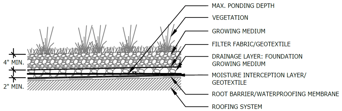
Figure 4.14‑3: Partially paved blue‑green roof with micro siphon drain belt standard detail
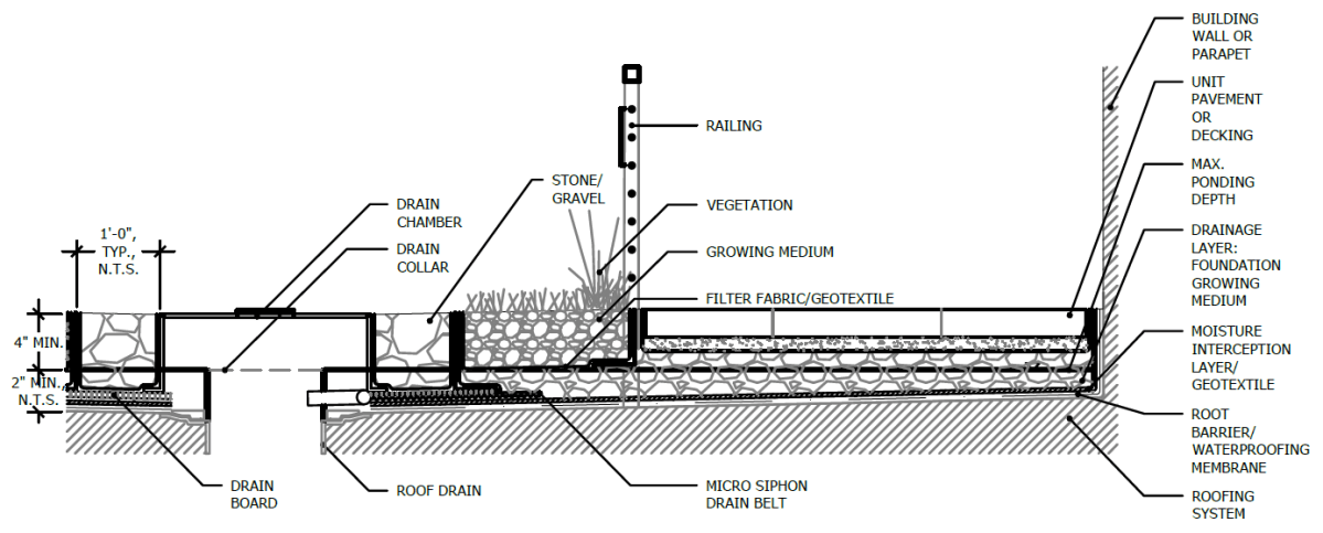
(The designer is referred to Appendix L to download Standard Detail CAD files.)
4.14.4 Blue‑green roof material standards
Inlet control material standards
- The designer is referred to Section 4.11 for information on material standards for inlet control systems.
Storage area material standards
- Green roof growing medium must be a lightweight mineral material with added organic material that meets the following specifications:
- Moisture content at maximum water holding capacity (ASTM E2399 or FLL): 40% to 60% (vol)
- Porosity at maximum water holding capacity (ASTM E2399 or FLL): 10% to 15%
- Density at maximum water holding capacity (ASTM E2399 or FLL): ≤ 85 lbs/ft3
- Total organic matter (MSA): 6% to 10% (dry weight)
- pH (MSA): 6.5 to 7.8
- Soluble salts (DPTA saturated media extraction): ≤ 2 mmhos/cm
- Water permeability (ASTM E2399 or FLL): 0.25 in/min to 1.25 in/min
- Grain-size distribution consisting of ≤ 4.5% passing for clay (0.002 mm) and 5% to 15% passing for silt (0.05 mm). Clay and silt together must not exceed 15%.
- The nutrients must be initially incorporated in the formulation of a suitable mix for the support of the specified plant materials.
- The medium must withstand freeze/thaw cycles.
- Foundation growing medium (lightweight drainage aggregate) must be composed of a blended medium that meets the following specifications:
- Density at maximum water capacity (ASTM E2399‑05): ≤ 65 lbs/ft3
- Maximum water holding capacity: 15% to 25%
- Water permeability (ASTM E2396‑05): ≥ 25 in/min
- Total organic matter by loss on ignition (ASTM F1647): ≤ 1%
- Porosity (ASTM C29): 20% to 65%
- Grain-size distribution (ASTM C136) consisting of the following gradations:
- Pct. Passing US#18 sieve (1.0 mm): ≤ 5%
- Pct. Passing ¼‑inch sieve: ≤ 30%
- Pct. Passing 3/8‑inch sieve (9.5 mm): ≥ 75%
- Pct. Passing ½‑inch sieve (12 mm): 100%
- Geotextile must consist of polypropylene fibers and meet the following specifications:
- Grab Tensile Strength (ASTM-D4632): 70 lbs to 120 lbs
- CBR Puncture Strength (ASTM-D6241): 120 lbs to 340 lbs
- Flow Rate (ASTM-D4491): 130 gal/min/ft2 to 200 gal/min/ft2
- UV Resistance after 500 hrs. (ASTM-D4355): 70%
- Tear Resistance (ASTM-D4533): 30 lbs to 50 lbs
- Heat-set or heat-calendared fabrics are not permitted.
- Root Barrier/Waterproofing Membrane
- PVC, EPDM, and thermal polyolefin (TPO) are permitted and inherently root resistant.
- All waterproof membranes must meet appropriate ASTM specifications. PVC membranes must meet ASTM D4434 requirements, EPDM membranes must meet ASTM D4637 requirements, and TPO membranes must meet ASTM D6878 requirements.
- Waterproofing membrane must be fully waterproof with properly sealed seams, corners, and protrusions to prevent any intrusion of standing water above the membrane.
- Roofing membranes must meet all building code requirements and guidelines of the City of Philadelphia.
Vegetation material standards
- Invasive species are not permitted in green roof planting. All plants must be appropriate and compatible with soil, hydrologic, light, and other site conditions. The designer is referred to Appendix I for plant lists.
- Plant species must be biodiverse. Species diversity for green roofs is defined as follows:
- Sedum: Include at least two genera (i.e., both Sedum and Phedimus) and six different species or cultivars in planting plans.
- Native or adaptive grasses: Provide at least two genera and three different species, if grasses are included in the design.
- Native or adaptive perennials: Provide at least three genera and four different species, if perennials are included in the design.
- Plant establishment:
- Plant establishment may be achieved through plugs, mats, container plants and/or seed.
- The inclusion of seed as a supplement to live plants is required. The designer is referred to Section 4.13.3, Landscape Design Considerations, for a list of species appropriate for overseeding on green roofs.
- Temporary erosion control measures must be provided appropriate to the planting method during the plant establishment period.
- Perennials, grasses, grass-like plants, and groundcover plants must be healthy, well-rooted specimens.
- Green roof plantings must be able to withstand heat, cold, and high winds. After establishment, the plants must be self-sustaining and tolerant of drought conditions, with little to no need for fertilizers or pesticides.
- The only sedum known to be invasive, and which must be avoided is Sedum sarmentosum, also known as star sedum, gold moss, stringy stonecrop, or graveyard moss.
Outlet control material standards
- The designer is referred to Section 4.12 for information on material standards for outlet control systems.
Inspection and maintenance access materials standards
- Personal protection systems must comply with OSHA Fall Protection Safety Standards and the ANSI and ASSE consensus-based fall protection standards.
4.14.5 Blue‑green roof construction guidance
Proper construction of blue‑green roofs is essential to ensure long-term functionality and reduce long-term maintenance needs. Blue‑green roof systems are best installed by experienced roofing contractors with expertise in installing flat roof membranes over new or existing roof structures. A standard construction sequence for proper blue‑green roof system installation is provided below. This can be modified to reflect different blue‑green roof system applications or expected site conditions.
- Inspect waterproof membrane along the roof and parapet wall or any irregularities that will interfere with drainage or may cause leaks. Do not continue until roofer has addressed defects. Confirm height of membrane is at least six inches above the peak ponding elevation as per the SMP designs.
- Confirm all edges, seams, corners, protrusions, and other anomalies are sealed in a watertight manner consistent with the installation specifications of the membrane manufacturer.
- Install root barrier layer, if required.
- Install moisture management layer or geotextile, as appropriate to the design.
- Install drainage layer.
- Install filter fabric, as appropriate to the design.
- Install growing medium, as specified.
- Install irrigation system within the growing medium, if included in design.
- Test the irrigation system, if included in design.
- Install outlet controls in a manner consistent with the City’s Building and Plumbing Codes and guidelines. The designer is referred to Section 4.12 for information on sizing and installation of outlet control systems. Outlet systems must include a bypass/overflow mechanism to permit rapid discharge when the storage volume of the blue‑green roof system is exceeded.
- Finish installing and grading growing medium.
- Install wind protection, if included in the design. A wind scour blanket or hydromulch may be required to prevent erosion during the establishment period. It generally takes about two growing seasons for full establishment. High wind environments may necessitate permanent wind blankets.
- Establish vegetation:
- Blue‑green roof vegetation can be effectively established by broadcasting fresh sedum cuttings during the spring and fall months. Depending on seasonal conditions, irrigation may be required after planting.
- Many perennial plants can be installed as plugs or container plants between April and November. Depending on the time of planting, temporary irrigation may be required.
- Perennials can be established from seed, except during the months of June, July, and August.
4.14.6 Blue‑green roof maintenance guidance
Maintenance of blue‑green roof systems emphasizes maintaining drainage capacity, the health of vegetation, and prevention of clogging via periodic removal of sediment and debris from outlet areas. To maximize the blue‑green roof’s lifespan, inspect all facility components, including vegetation, growing medium, filter fabric, drainage layer, and visible portions of the waterproof membrane.
Regardless of plant density and coverage, control of weed species is encouraged as part of long-term maintenance. The designer is referred to the Landscape Design Guidebook for more detail.
General recommended maintenance activities for blue‑green roof systems are summarized in Table 4.14‑1.
Table 4.14‑1: Blue‑green roof maintenance guidelines
Early maintenance activity Frequency Inspect outlet structures, and storage areas for trash and sediment accumulation. Monthly for the first year after installation to determine ongoing maintenance frequency Water vegetation in the early morning. Every day for the first two weeks after planting. Every four days for the first year after planting, during periods of four or more days without rain, during June through August. Hand-weed non-target/invasive plants. Every three months for the first two years after planting. Inspect vegetation for signs of disease or distress. Treat or replace as necessary. Every two weeks for the first year after planting. Ongoing maintenance activity Frequency Remove debris from drainage outlets and outlet screens to prevent clogging. During inspections or as needed to ensure performance Remove debris from secondary drainage/overflows. During inspections or as needed to ensure performance Remove excessive buildup of sediment around the outlet controls or within the storage cells. During inspections or as needed to ensure performance Roof drains must be cleared when soil substrate, vegetation, debris or other materials clog the drain inlet. Under normal operating conditions, all roof discharge must be filtered, and medium must not be vulnerable to migration towards the drains. Sources of sediment and debris must be identified and corrected. As needed Break up ice formation around outlets and overflows. As needed during winter months Maintain plant material to provide a minimum of 80% foliage cover during warm months. If coverage rate is declining, determine the reason (e.g., soil nutrition or soil moisture conditions) and implement remedial measures. As needed (see below) Remove weeds manually and use herbicide only in extreme instances of weed infestations that compromise the plant cover integrity and when herbicides are permitted on a project site (e.g., certain sustainability rating systems do not allow chemical herbicides on site). Remove weeds entirely. As needed (see below) Thin any overgrown areas of vegetation As needed Inspect for leaks During inspections or as needed to ensure performance Inspect root development. If root zone is not well developed, determine the reason (e.g., soil nutrition, soil moisture conditions) and implement remedial measures. Quarterly Inspect permanent irrigation system and adjust irrigation dosing rates as needed to optimize plant performance and water-use efficiency. Quarterly Inspect growing medium for evidence of erosion from wind or water. If erosion channels are evident, a problem with the drainage system or with the growing medium is present. Surface ponding or runoff must not occur except during very large rainfall events. Correct the problem, then refresh the affected areas with additional growing medium and provide temporary soil stabilization. Quarterly In early spring, manually cut dormant herbaceous vegetation from the previous growing season to four to six inches above the ground. Annually Inspect drain-inlet pipe and containment system. Annually Test growing medium for soluble nitrogen content. Fertilize as needed. Annually Maintain records of all inspections and maintenance activity. Ongoing During the plant-establishment period, conduct at least three to four maintenance visits yearly for basic weeding, fertilization, and in-fill planting. Thereafter, conduct at least two annual inspection and light weeding visits (irrigated assemblies will require more frequent maintenance).
Herbicides must be avoided to prevent root penetration of waterproofing.
Apply organic or chemical fertilizer according to soil-testing results to maintain soluble nitrogen (nitrate and ammonium ion) levels between one and four ppm. Mature compost is the best nutrient source for fertilization.
Exercise spill prevention measures from mechanical systems located on roofs when handling substances that can contaminate stormwater.
The designer is referred to Section 4.12, Outlet Controls, and Section 4.13, Landscaping, for information on maintenance guidance for outlet controls and landscaping.
-
4.15 Drainage Wells
Download summaries of this SMP and its maintenance guidance, with quick reference information for clients and developers:
4.15.1 Drainage well introduction
Drainage well stormwater management practices (SMPs) are perforated stormwater manholes that detain runoff and allow it to infiltrate into the surrounding soil. Stormwater flows into the drainage well where it collects within the manhole structure and surrounding open-graded stone. Drainage wells are typically constructed from precast concrete or a thermoplastic (typically polyvinyl chloride, or PVC). Drainage wells are a specific application of subsurface infiltration and are typically deeper than other types of infiltration SMPs. The designer is referred to Section 4.4 for more general information on subsurface infiltration SMPs.
Drainage wells can be combined with other SMPs in series to meet the Philadelphia Water Department (PWD) Stormwater Regulations (Stormwater Regulations). The designer is referred to Section 3.2.3 for information on using SMPs in series.
This design guidance provides flexibility for designers to dynamically model drainage wells. Dynamic routing allows designers to account for the volume of water infiltrated into the ground in real time, which allows the drainage well to have less storage and be shallower. Design of drainage wells is not limited to the examples discussed within this text. Successful stormwater management plans will combine appropriate materials and designs specific to each site.

An example of a precast concrete drainage well in Philadelphia Where can drainage wells be used?
Drainage wells must have underlying soils that, when tested pursuant to the protocol described later in this section (Section 4.15.3), are determined to be infiltration-feasible. They can be used to manage stormwater on both small and large sites, but may be especially useful on smaller sites, where open space for bioinfiltration/bioretention SMPs and horizontal area for subsurface infiltration are limited. For large sites, multiple drainage wells can be integrated throughout the site to manage larger areas. Provided that overburden loads and utility conflicts are evaluated, they can be sited beneath lawns and recreational areas, as well as parking lots and other hardscape surfaces. Drainage wells can also be dynamically sized to save space or reduce the depth of the SMPs.
Key advantages of drainage wells
- Can be useful on smaller sites with limited area available for bioinfiltration or subsurface infiltration footprints
- Can be easier to maintain than other subsurface infiltration types
- Less reliant on infiltration through the bottom surface of the SMP than other subsurface infiltration SMPs. Therefore, reduction in infiltration through the bottom of the SMP as a result of clogging may not be as detrimental to the long-term performance of drainage wells as it is to other subsurface infiltration SMPs.
- Eligible for dynamic sizing
Key limitations of drainage wells
- Can be more costly and more challenging to install than surface practices like bioinfiltration SMPs, as well as more difficult to maintain post-construction
- Because identification of the seasonal high-water table is so important to the design of a drainage well, and because drainage wells are generally deeper than other subsurface SMPs, monitoring of the water table over a period of time using groundwater monitoring wells is recommended. Monitoring may lengthen the time needed for design. Furthermore, if monitoring reveals a water surface elevation that is too high for the drainage well to function properly, alternate siting or an alternate design would be necessary.
- Not appropriate for runoff with high sediment loads without robust pretreatment
- Requires regularly scheduled inspections because the maintenance needs are not easily visible
- Does not improve natural aesthetics or provide the ancillary environmental benefits associated with vegetated SMPs, such as habitat creation and improved air quality
Key design considerations for drainage wells
- Must be constructed in soils suitable for infiltration. Infiltration in both vertical and horizontal directions should be considered.
- Drainage wells can be dynamically designed, which may save space or reduce the depth of the SMPs. These SMPs must statically store one inch of runoff and be shown, via dynamic routing, to manage 1.5 inches of runoff throughout the design storm, without overflow.
- The horizontally exfiltrating section of the drainage well should not be constructed in unstable fill. Designers are specifically cautioned against siting drainage wells in inappropriate fill high in ash, cinder, or brick fragments, which are prone to dissolving or washout. Horizontal infiltration should occur below any problematic fill.
- Must confirm depth to bedrock, water table, or other hydraulically limiting layers.
- Because drainage wells may be deeper than other subsurface infiltration SMPs, careful identification of the seasonal high water table is especially important. Continuous soil borings from the surface to a depth five feet below the proposed drainage well bottom is required. Further drilling to the observed water surface elevation and installation of a groundwater monitoring well and monitoring of the water surface elevation over a period of time (generally, from March through October) are recommended. Monitoring data and evaluation of samples from the continuous soil borings should be used to physically identify the seasonal high groundwater table. This must be reported in the Geotechnical Report, further outlined in Section 3.3.
- Appropriate pretreatment should be provided to remove sediment and debris before discharging to a drainage well system. A pretreatment approach should be developed based on the expected level of sediment loading and difficulty of sediment removal.
- Manhole structure diameter, the dimensions of the surrounding open-graded stone, and the depth of the drainage well system should be adjusted to provide appropriate runoff volume storage and management.
- Long-term maintenance must be carefully considered when evaluating drainage well systems. The system and maintenance access should be located in an area where maintenance and potential repairs can be conducted with minimal disturbance to surrounding uses.
- Improper installation of manholes has been known to result in subsidence in the area directly around the manhole. Proper compaction of stone and suitability of surrounding soils must be verified to minimize subsidence in the area around the drainage well.
- Structural suitability for overburden support and traffic loading should be considered, where applicable.
- Areas of soil contamination or unstable soils may need to be remediated or stabilized prior to drainage well installation.
- For any drainage well that discharges onto an adjacent property, a drainage easement is required.
Drainage well materials
Drainage wells may be designed and constructed in a variety of sizes and materials. In this section, we discuss two main types of material:
Precast concrete drainage wells consist of a perforated, reinforced precast concrete manhole, with cast iron frame and cover, surrounded by open-graded stone. Precast concrete drainage wells are typically designed for AASHTO HS-20 loading and are therefore able to be used under areas that experience vehicle traffic, like driveways and parking lots.
Thermoplastic drainage wells consist of a perforated, thermoplastic (typically PVC) manhole, with steel frame and cover, surrounded by open-graded stone. Thermoplastic drainage wells are typically designed for AASHTO H-20 loading and are therefore able to be used under areas that experience vehicle traffic, like driveways and parking lots. However, precast concrete drainage wells may be preferable where heavy vehicle loads are anticipated.
4.15.2 Drainage well components
Figure 4.15‑1: Precast concrete drainage well with typical features
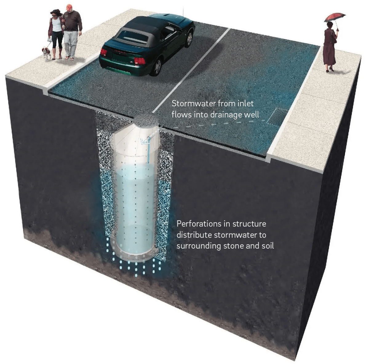
Pretreatment component
Pretreatment systems capture trash, sediment, and pollutants from stormwater runoff before delivery to the infiltration area. Pretreatment needs will vary significantly depending on the contributing drainage area composition and use. Pretreatment can include structures such as sumped and trapped inlets, sediment/grit chambers or separators, media filters, inlet inserts, or other appropriate prefabricated or proprietary designs to remove sediment, floatables, and/or hydrocarbons from stormwater runoff prior to being conveyed to a drainage well. Pretreatment can also consist of filter strips, forebays, and swales. The designer is referred to Section 4.10, Pretreatment, for more information on pretreatment systems.
Inlet control component
Inlet control systems convey and control the flow of stormwater from the contributing catchment area to a drainage well. Inlet control needs will vary depending on the design of stormwater conveyance systems and the site layout. The designer is referred to Section 3.4.2 for guidance on stormwater conveyance system design.
Inlet controls may include flow splitters, curbless design/curb openings, energy dissipaters, and inlets. The designer is referred to Section 4.11, Inlet Controls, for more information on inlet controls.
Storage area component
Storage areas within drainage wells temporarily hold stormwater runoff as it infiltrates into surrounding soils. The storage component of a drainage well is typically constructed of a perforated precast concrete or thermoplastic manhole, surrounded by open-graded stone. The open space within the manhole and the void spaces between the stones store stormwater until it can infiltrate into the surrounding soils. Accounting for these void spaces, the drainage well’s storage volume may be calculated using the width of excavation measured at the extents of the stone surrounding the well (i.e. excavation diameter) and the depth of the well from the bottom of the stone to the overflow invert (i.e. infiltrating depth).
Outlet control component
Outlet controls within a drainage well can provide a range of functions, including the following:
- Controlling how much water is stored for infiltration;
- Meeting drain down time requirements;
- Controlling the rate of discharge from the SMP and limiting water surface elevations during various storm events; and/or
- Bypassing of flows from large storm events
Outlet controls may include orifices or overflow pipes. The designer is referred to Section 4.12, Outlet Controls, for more information on outlet controls. Typically, a separate structure outside the drainage well manhole is needed to regulate discharge from a drainage well that does not infiltrate into surrounding soils.
Inspection and maintenance access component
Safe and easy inspection and maintenance access to all major components within a drainage well system is critical to ensuring long-term performance. Access points provide access to the drainage well manhole as well as inlet and outlet controls, both for inspections and routine maintenance.
4.15.3 Drainage well design standards
If infiltration is deemed feasible, the designer may elect to dynamically design the drainage well. The dynamically designed SMP must still meet all applicable requirements, but it may be designed to statically store one inch of runoff, rather than the full 1.5‑inch Water Quality Volume (WQv). If this strategy is chosen, the designer must show, via dynamic routing, that the full 1.5‑inch WQv is managed throughout the design storm, without overflow.
General design standards
- The maximum allowable drain down time is 72 hours after the 24‑hour storm event.
- There is no maximum directly connected impervious area (DCIA) to SMP footprint loading ratio.
- Positive overflow must be provided for large storm events, up to and including the 100‑year, 24‑hour storm, or, if the project is exempt from Flood Control, the ten‑year, 24‑hour storm. Overflow structures and pipes must be designed to convey at least the ten‑year, 24‑hour storm.
- The minimum allowable distance between the edge of a drainage well’s stone storage bed and any adjacent private property line is ten feet. It is acceptable for drainage wells to be located directly adjacent to the public right-of-way (ROW).
- The minimum allowable distance between the edge of a drainage well’s stone storage bed and any building or retaining wall is ten feet. The following requirements and exceptions apply:
- For existing and proposed buildings with basements, the setback is measured from the basement wall.
- For existing buildings without basements and existing retaining walls, the setback is measured from the foundation and may be waived if a signed and sealed geotechnical analysis is submitted that evaluates the impacts of infiltration and excavation on the existing foundation and determines it to be feasible.
- For proposed buildings without basements and proposed retaining walls, the setback is measured from the foundation and may be waived if the foundation is proposed to be designed with the drainage well’s proximity in mind.
- When siting two or more drainage wells near each other, the lateral clearance between the edges of their stone storage beds must be twice the distance of the height of the perforated well section.
- Infiltration requirements:
- The drainage well must be located at least two feet above any poorly infiltrating soils, seasonal high groundwater table, bedrock, or other hydraulically limiting zone.
- For hydrologic modeling, a soil permeability coefficient (k20), calculated per the protocol described below in 7c(vi), must be applied to the wetted area of the drainage well, spanning the perforated sides and bottom, to determine infiltration characteristics.
- Because drainage wells utilize infiltration through the bottom as well as the sides, the infiltration testing protocol is different than other for other subsurface infiltration SMPs. Infiltration testing for drainage wells must be performed according to the following procedure, which is a modified version of the United States Bureau of Reclamation (USBR) Procedure 7300, Performing Field Permeability Testing by the Well Permeameter Method:
- Install a PVC well cap on one end of a four‑inch inner diameter, Schedule 40 PVC well screen and lower into a borehole (ASTM D6151‑08). The cap should be securely attached, making a positive seal. Sections of well screen should be added corresponding to the proposed length of perforated sections of the planned drainage well.
- A section of solid PVC casing corresponding to the depth below the ground surface to the top of the drainage well perforations should be connected to the slotted well screen section and extended to the ground surface.
- PVC well screen shall be new and flush threaded as per ASTM standards (ASTM D6724). The slot size of the well screen should be 0.060 inches (60 slot). The annulus between the well screen and the borehole should be filled with gravel pack, U.S. Silica FilPro #4 or equivalent.
- Infiltration testing shall be conducted by measuring the flow rate that is needed to maintain a constant head in the well. Use of a reservoir and float valves as described in USBR 7300 is suitable, but not required. Variations to the reservoir set up and the maintenance of the constant head are permitted as long as measurement of flow can be accurately made. Constant head should be maintained within one foot of the surface (keeping the water level above the slotted screen interval at all times). Once the water level has stabilized, record the volume loss from the constant head reservoir over time. Specific increments are not given in the USBR 7300 procedure, but regular increments should be used, at least every 15 minutes. As per USBR 7300, the test should be continued for at least 4 hours without letting the reservoir completely empty.
- Upon completion of the infiltration test and all relevant logs, the well screen should be removed (if possible) and the hole backfilled with the cuttings. The surface should generally be restored using a concrete or asphalt patch. If the PVC materials cannot be retrieved, the casing extension should be removed or should be cut to at least six inches below the surface.
- The permeability coefficient (k20) should be computed as follows:
- If the depth to the water table or impermeable layer is greater than three times the depth of the water in the test well:
- If the depth to the groundwater table or impermeable layer is less than three times the depth of water in the well:
- Where:
- k20 = coefficient of permeability at 20 degrees Celsius
- h = height of water in the well
- r = radius of the well
- q = discharge rate of water from the well for steady-state constant head condition (determined from the straight line of a graph of total volume vs time (see Figure 7 in USBR 7300)
- V = viscosity of water at 20 degrees Celsius
- Tu = unsaturated distance between the water surface in the well and the water table
- If the depth to the water table or impermeable layer is greater than three times the depth of the water in the test well:
- If the drainage well location is used as a temporary sediment basin during construction, the invert elevation of the infiltration SMP must be a minimum of three feet below the bottom elevation of the pre-basin-conversion sediment basin.
- A drainage well within the zone of influence of any nearby basements, sewers or sewer laterals, or other subsurface conditions where infiltration is not advisable must be installed with an impervious liner. The zone of influence is defined by the area within a 1:1 (H:V) slope line from the outer edge of a sewer or sewer lateral.
- Structural suitability for overburden support and traffic loading must be considered, where applicable.
Pretreatment design standards
- Acceptable form(s) of pretreatment must be incorporated into design. Pretreatment of runoff from all inlets is required. At a minimum, this can be achieved through the use of sumps and traps for inlets, sump boxes with traps downstream of trench drains, and filter strips for overland flow.
- The designer is referred to Section 4.10, Pretreatment, for more information on design standards for pretreatment systems.
Inlet control design standards
- The designer is referred to Section 4.11, Inlet Controls, for information on design standards for inlet control systems.
Storage area design standards
- The storage area must provide static storage for the WQv between the bottom elevation of the SMP and the elevation of the lowest outlet, including storage voids. For dynamically designed drainage wells, static storage of only one inch of the WQv must be provided if the designer demonstrates, through dynamic routing, that the full 1.5‑inch WQv is managed throughout the design storm, without overflow.
- The maximum allowable static storage volume without supporting documentation (defined below) is the runoff volume from the one‑year, 24‑hour storm.
- The maximum allowable static storage volume with supporting documentation is the runoff volume from the ten‑year, 24‑hour storm. Requirements for supporting documentation include a letter, signed and sealed by both the geotechnical and design engineer, indicating that the proposed design is recommended, with the following components acknowledged and considered. The designer is encouraged to contact PWD for further guidance when pursuing this design.
- A summary of the long-term impacts to the neighboring properties, including, but not limited to subsidence, change in basement moisture/water, and structural damage;
- The location of the groundwater table;
- References to other projects that have successfully infiltrated more than the one‑year, 24‑hour storm event; and
- Rigorous pretreatment to promote longevity of the infiltration SMP.
- When SMPs are used in series, the storage areas for all SMPs must provide cumulative static storage for the WQv, but there is no minimum storage requirement for each individual SMP used in series.
- Drainage wells can be designed with additional storage beyond the WQv and with outlet controls that allow all remaining applicable Stormwater Regulations to be met.
- Void space provided by drainage wells must be as specified by the manufacturer and noted in supporting documentation.
- Bedding and foundations:
- Drainage wells must be adequately bedded on stone to prevent settling or subsidence.
- Bedding thickness may vary according to system requirements, but must not be less than six inches.
- Over-excavation and replacement of loose or unstable subsurface material may be required if such conditions are encountered. A geotechnical engineer or other appropriate design professional should be consulted for additional guidance.
- Foundations/footers must be provided as warranted by system loading, geotechnical conditions, and manufacturer’s recommendations. Foundation designs must be performed by an appropriate design professional.
- The storage design must account for potential loading from vehicles, as appropriate, based on expected maximum active loading, including consideration for emergency vehicles.
- A porosity of 0.40 must be used for stone storage volume calculations.
- Stone must be separated from existing soil media by a geotextile, to prevent sand, silt, and sediment from entering the system. A pea gravel filter may be used on the bottom in lieu of a geotextile.
- Stone must be separated from the perforated manhole by a geotextile or geogrid to prevent stone from falling into the manhole.
- Drainage wells must have a level bottom. If installed in series, along a slope, drainage wells must use a terraced elevation system.
Outlet control design standards
- The designer is referred to Section 4.12, Outlet Controls, for information on design standards for outlet control systems.
Inspection and maintenance access design standards
- Manholes must be accessible, to allow unobstructed and safe access to drainage wells for routine inspection and maintenance. Inlet and outlet controls must also contain access panels or other access features to inspect and maintain the same.
- Ladder access is required for drainage wells greater than four feet in height.
Figure 4.15‑2: Precast concrete drainage well standard detail
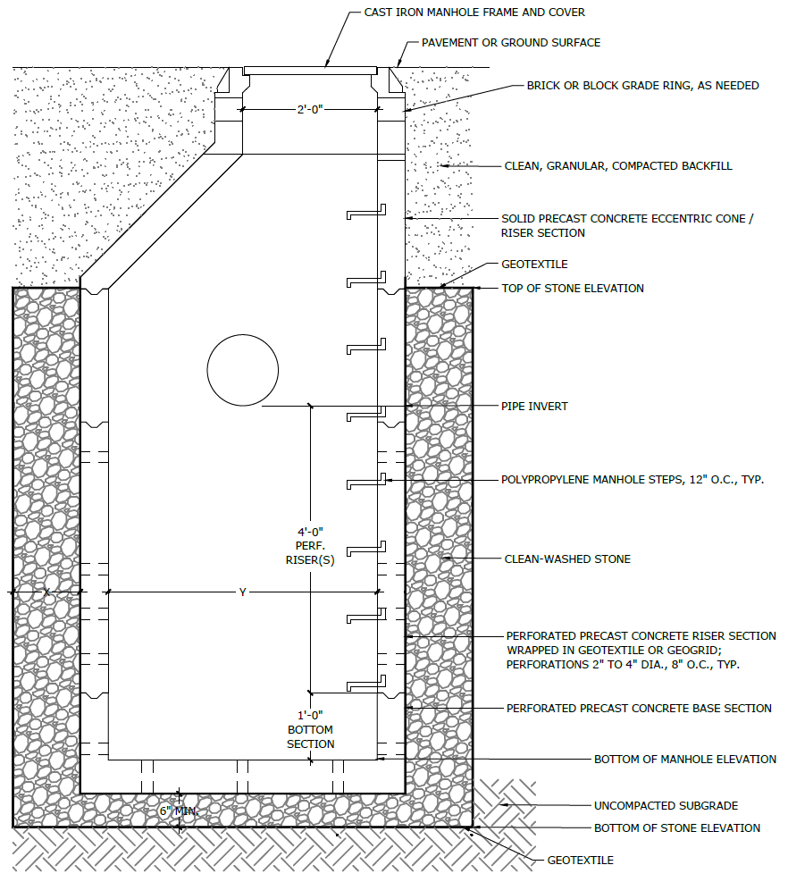
Figure 4.15‑3: Thermoplastic drainage well standard detail
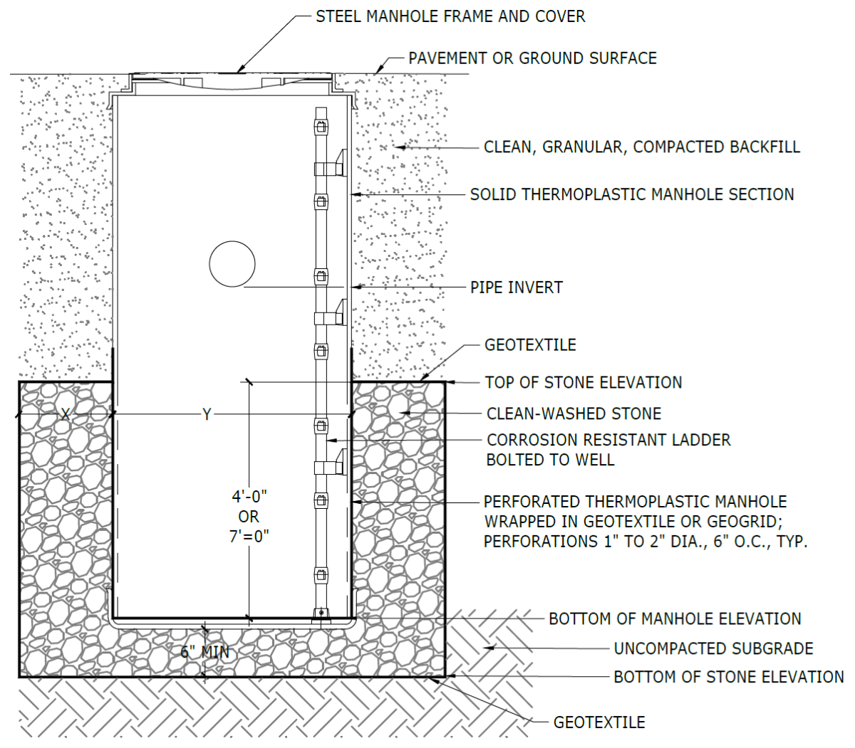
(The designer is referred to Appendix L to download Standard Detail CAD files.)
4.15.4 Drainage well material standards
Pretreatment material standards
- The designer is referred to Section 4.10, Pretreatment, for information on materials standards for pretreatment systems.
Inlet control material standards
- The designer is referred to Section 4.11, Inlet Controls, for information on material standards for inlet control systems.
Storage area material standards
- Precast concrete drainage well manholes must meet the following specifications:
- Concrete risers: five‑inch thick, 4,000 psi concrete, 3×12 WWF (six gauge) reinforcement
- Base section: nine‑inch thick, 4,000 psi concrete, #4 rebar reinforcement, six inches on center
- Perforations: two to four‑inch diameter, eight inches on center
- Connections to be made with non-shrink grout
- Thermoplastic drainage well manholes must meet the following specifications:
- Thermoplastic well sections: PVC
- Perforations: one to two‑inch diameter, six inches on center
- Connections to be made with like materials per manufacturer recommendations
- Stone designed for stormwater storage must be uniformly graded, crushed, clean-washed stone. PWD defines “clean-washed” as having less than 0.5% wash loss, by mass, when tested per American Association of State Highway and Transportation Officials (AASHTO) T-11 wash loss test. AASHTO No. 3 and No. 57 stone can meet this specification.
- Geotextile, if used, must consist of polypropylene fibers and meet the following specifications (AASHTO Class 1 or Class 2 geotextile is recommended):
- Grab Tensile Strength (ASTM-D4632): ≥ 250 lbs
- CBR Puncture Strength (ASTM-D6241): ≥ 500 lbs
- Flow Rate (ASTM-D4491): ≥ 95 gal/min/ft2
- UV Resistance after 500 hrs (ASTM-D4355): ≥ 70%
- Tear Resistance (ASTM-D4533): ≥ 80 lbs
- Heat-set or heat-calendared fabrics are not permitted
- Geogrid, if used, must meet the following specifications:
- Maximum Apparent Opening Size (AOS): 0.25‑inch
- Grab Tensile Strength (ASTM-D4632): ≥ 205 lbs
- CBR Puncture Strength (ASTM-D6241): ≥ 500 lbs
- UV Resistance after 500 hrs (ASTM-D4355): ≥ 70%
- Tear Resistance (ASTM-D4533): ≥ 80 lbs
Outlet control material standards
- The designer is referred to Section 4.12, Outlet Controls, for information on material standards for outlet control systems.
Inspection and maintenance access material standards
- Manhole covers must allow access to drainage well.
4.15.5 Drainage well construction guidance
Proper construction and careful consideration of soil compaction, infiltration performance, and sedimentation control of drainage wells are essential to ensure long-term functionality and reduce long-term maintenance needs and costs. Construction oversight is critical. At a minimum, verification of volumes, grades, and elevations must be performed prior to backfill.
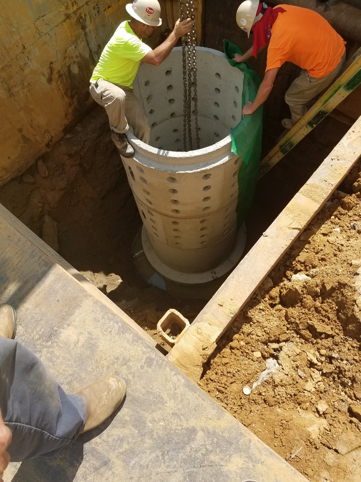
An example of a drainage well installation in Philadelphia - If the contractor proposes to install deep drainage wells, especially if using drilled caissons, a Vibration Monitoring Plan is recommended. The contractor should monitor vibrations and stop work and reevaluate the proposed system with the Engineer if excessive vibrations are identified.
- Areas for proposed drainage wells must be physically marked as heavy equipment exclusion zones prior to any land-disturbing activities to avoid soil disturbance and compaction during construction. Install construction fencing around drainage well areas. If areas are compacted during construction, additional infiltration testing and potential redesign may be required.
- Provide erosion and sedimentation control protection on the site such that construction runoff is directed away from the proposed drainage well. Sediment deposited in a drainage well during construction, may significantly reduce SMP performance. The designer is referred to the latest edition of the Pennsylvania Department of Environmental Protection (PA DEP) Erosion and Sediment Pollution Control Program Manual for information on design standards for erosion and sedimentation control practices.
- Drainage well areas may not be used as sediment traps during construction, unless at least three feet of soil are left in place while the area is serving as a sediment trap and subsequently removed during construction after the contributing drainage areas have been stabilized.
- Complete site elevation grading and stabilize all disturbed soil. Stabilization of disturbed areas must be implemented before finalizing the drainage well’s excavation and construction.
- Excavate drainage well to proposed depth and manually grade and scarify the horizontal and vertical existing soil surfaces. The bottom of the drainage well footprint must be at a level grade.
- Existing subgrade must not be compacted or subject to excessive construction equipment prior to placement of geotextile and stone bed. The use of machinery to load stone from outside of the drainage well footprint is recommended. Stone should be carefully placed in the drainage well excavation. Should the subgrade be compacted during construction, additional testing of soil infiltration rates and SMP redesign may be required. Rock construction entrances must not be located on top of areas proposed for drainage wells.
- Place geotextile and stone immediately after approval of subgrade preparation to prevent accumulation of debris or sediment. Prevent runoff and sediment from entering the drainage well excavation during the placement of the geotextile and stone.
- Place geotextile in accordance with manufacturer’s standards and recommendations.
- Install bedding stone in lifts no greater than eight inches. Lightly compact each layer with equipment, keeping equipment movement over stone bedding material to a minimum. Install stone to grades indicated on the drawings.
- All stone that is used in the drainage well system must remain free of sediment. If sediment enters the stone, the contractor may be required to remove the sediment and replace with clean washed stone.
- Confirm and document invert elevations and dimensions of all structures such as connections and pipes prior to backfill.
- Backfill to finished grade. Ensure backfill is properly compacted in accordance with specifications. Ensure backfill process does not disrupt pipe placement and configuration.
- Structures such as inlet boxes, reinforced concrete boxes, inlet controls, and outlet controls must be constructed according to manufacturer’s guidelines or design professional’s guidance.
- Complete surface grading above and around drainage well, using suitable equipment to avoid excess compaction.
- Once the site is permanently stabilized with vegetation or hardscaping, remove temporary erosion and sediment control measures.
4.15.6 Drainage well maintenance guidance
Maintenance of drainage wells focuses on the periodic removal of sediment and debris from pretreatment and storage areas. Sediment removal from vaults, chambers, and pipes is typically conducted using vacuum or flushing systems. Considerations for inspection and maintenance equipment access to the drainage well and associated structures are critical to successful long-term maintenance. Guidance on the use and operation of vacuum or flushing sediment removal equipment is beyond the scope of this Manual; a maintenance professional should be contacted for additional details. As applicable, drainage well maintenance procedures must meet OSHA confined space entry requirements.
General recommended maintenance activities for drainage wells are summarized in Table 4.15‑1.
Table 4.15‑1: Drainage well maintenance guidelines
Early maintenance activity Frequency Inspect erosion control and flow spreading devices until soil settlement and vegetative establishment of contributing areas has occurred. Biweekly Inspect inlet controls, outlet structures, and storage areas for trash and sediment accumulation. Remove debris and sediment as necessary. Monthly for the first year after installation to determine ongoing maintenance frequency Ongoing maintenance activity Frequency Regularly clean out gutters and catch basins to reduce sediment load to drainage well. Clean intermediate sump boxes, replace filters, and otherwise clean pretreatment areas in directly connected systems. As needed Remove sediment and debris from drainage well pretreatment sediment/grit chamber or separator, if applicable, when the sediment zone is 3/4 full. Sediment and debris build up may need to be removed by a professional. Consult with a professional as necessary. As needed Remove sediment and debris from drainage well when the sediment accumulates to three inches or more. As needed Replace filter bags for pretreatment devices. Please ensure filter bag is installed properly. Quarterly Inspect drainage well and control structures. Quarterly Remove floating debris and accumulated petroleum products from the system and all components. Quarterly Evaluate the drain down time of the drainage well after a storm of at least one inch to ensure a drain down time of less than 72 hours. Ongoing Maintain records of all inspections and maintenance activity. Ongoing The designer is referred to Section 4.10, Pretreatment, Section 4.11, Inlet Controls, and Section 4.12, Outlet Controls, for information on maintenance guidance for pretreatment, inlet controls, and outlet controls.
PWD Stormwater Management Guidance Manual v3.4
Chapter 4 Stormwater Management Practice Guidance
