Download summaries of this SMP and its maintenance guidance, with quick reference information for clients and developers:
4.9.1 Media filter introduction
Media filters (also referred to as “filters” in this section) are structures or excavated areas containing a layer of sand, compost, organic material, peat, or other filter media. They reduce pollutant levels in stormwater runoff by filtering sediments, metals, hydrocarbons, and other pollutants. Filtered stormwater is then released to a sewer, receiving water, or downstream stormwater management practice (SMP). Media filters are designed to allow higher rates of stormwater flow than traditional filters. Sand and other rapid filter media enable smaller SMP footprints by allowing for faster filtration of stormwater.
Media filters can be combined with other SMPs in series to meet the Philadelphia Water Department (PWD) Stormwater Regulations (Stormwater Regulations). The designer is referred to Section 3.2.3 for information on using SMPs in series. Facilitating evapotranspiration, vegetated media filters are useful in meeting the Water Quality requirement when placed upstream of a non-infiltrating SMP. Non-vegetated media filters can assist in meeting the Water Quality requirement when placed upstream or downstream of a non-infiltrating SMP. For Stormwater Retrofits, media filters are needed for subsurface detention systems in the Municipal Separate Storm Sewer System (MS4).
The design of media filters is not limited to the examples provided within this text. Successful stormwater management plans will combine appropriate materials and designs specific to each site. Other types of prefabricated or proprietary filters such as water quality inserts fitted within inlets are available, but they are only to be used as pretreatment and are not considered SMPs.
Filters are evaluated on a project-specific basis since site conditions, such as sediment loading and/or drainage area size, can impact a product’s ability to meet Stormwater Regulations. Third-party certification of all performance claims is strongly encouraged for all prefabricated and proprietary devices. Examples of third-party certification programs include the New Jersey Department of Environmental Protection (NJDEP) and the Washington State Department of Ecology. The NJDEP certification uses the New Jersey Center for Advanced Technology (NJCAT) verification as conducted according to the Technology Acceptance and Reciprocity Partnership (TARP) Protocol. Washington State Department of Ecology uses the Technology Assessment Protocol – Ecology (TAPE). In addition to all certifications and laboratory test data, all performance claims should be supported by field test data where possible. PWD does not endorse the use of specific third-party certification programs, and specific programs are mentioned as examples only. PWD has developed a list, accessible on the PWD Development Services Resource Directory, of filter products that may be used to comply with the Stormwater Regulations. PWD allows the use of monitoring programs in lieu of, or in addition to, third-party certification.
The designer should note that there may be situations where PWD’s compliance requirements are more restrictive than a manufacturer’s specifications for a particular product; in these scenarios, the designer must engineer a solution that satisfies PWD standards.
When can media filters be used?
Media filters can be used on sites where vegetated SMPs are impractical due to limited surface area or other constraints. They can assist applicants in meeting the Water Quality requirement where infiltration is not feasible. Filters may be used alone in separate sewer areas, or upstream or downstream of detention practices as part of a series approach in combined sewer areas, to meet multiple Stormwater Regulations.
Key advantages of media filters
- Have highly flexible designs and configurations that can be useful in meeting the Water Quality requirement where space-constrained, highly developed, or otherwise challenging locations prevent the use of traditional surface-level or rooftop SMPs, and infiltration is not feasible
- Can be designed to be visible from the surface or completely subsurface, located beneath parking lots or other impervious areas
Key limitations of media filters
- Do not offer, when non-vegetated, many of the ancillary benefits associated with surface vegetated SMPs, including aesthetic value, improved air quality, and habitat creation
- Do not reduce the volume of stormwater runoff like bioretention basins and green roofs do
- May have sizing requirements that result in large footprints due to filtration rates for filter media such as sand
Key design considerations for media filters
- A primary design consideration for filters is site suitability. The use of a bioretention SMP should first be considered before selecting a media filter. Bioretention SMPs provide the same, or better, level of Water Quality treatment, provide a range of other economic and aesthetic benefits, and are typically easier to access and maintain.
- Philadelphia’s low temperatures are below freezing for approximately four months every year, and surface filtration may not function as well in the winter. Design options that allow direct subsurface discharge into filter media during cold weather may help overcome this condition.
- Filter media should be selected and sized to match the required rate of stormwater flow for the SMP. The designer should carefully consider the filtration rate of the media and the available storage volume in order to size the SMP.
- The maintenance access that is required for the filter system must be considered. Filter systems require frequent maintenance and may require different maintenance equipment than other SMPs.
- Proprietary media filters may inherently comply with many of the following design and material standards, in which case, submission of appropriate supporting documentation is critical.
- For any media filter that discharges onto an adjacent property, a drainage easement may be required and is recommended.
4.9.2 Media filter components
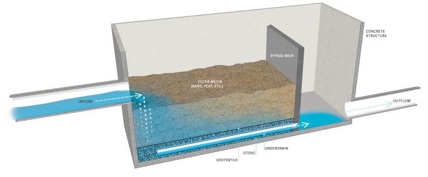
Figure 4.9‑1: Media filter with typical features
Pretreatment component
Pretreatment systems capture trash, sediment, and/or other pollutants from stormwater runoff before delivery to the storage area. Pretreatment needs will vary significantly depending on the contributing drainage area composition and use. Pretreatment can include structures such as sumped and trapped inlets, sediment/grit chambers or separators, inlet inserts, or other appropriate prefabricated or proprietary designs to remove sediment, floatables, and/or hydrocarbons from stormwater runoff prior to being conveyed to a filter system.
Pretreatment can also consist of filter strips, forebays, and swales. The designer is referred to Section 4.10 for more information on pretreatment systems.
Inlet control component
Inlet control systems convey and control the flow of stormwater from the contributing catchment area to a filter SMP. Inlet control needs will vary depending on the design of stormwater conveyance systems and the site layout. The designer is referred to Section 3.4.2 for guidance on stormwater conveyance system design.
Inlet controls may consist of flow splitters, curbless design/curb openings, energy dissipaters, and inlets. The designer is referred to Section 4.11 for more information on these types of inlet controls.
Storage area component
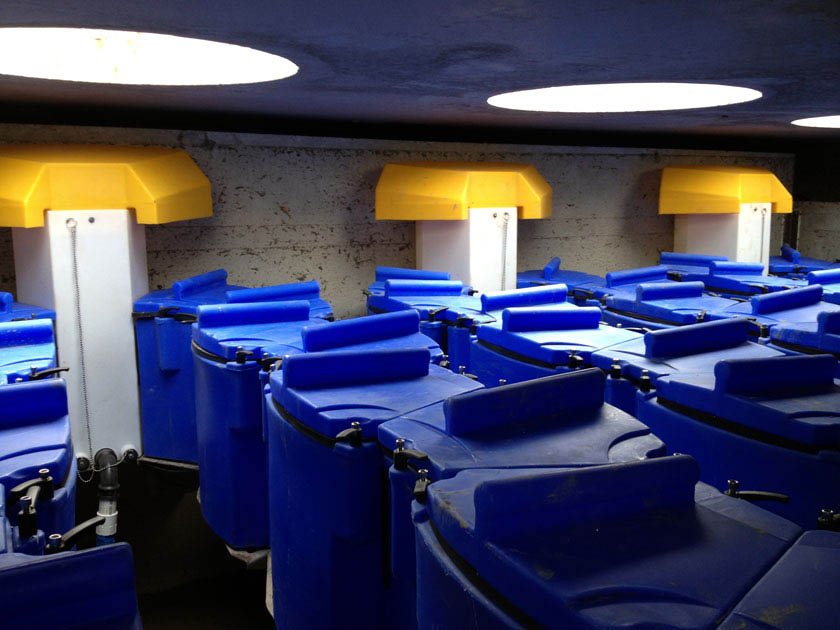
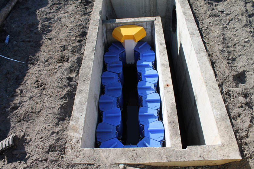
Storage areas within filter systems temporarily hold stormwater runoff before it can either pass through the filter media or be released downstream, depending on the system design and the size of the storm event. Storage for media filter systems can be located either above or below the ground surface. Surface storage is typically constructed by either excavating an area to create a depression or by erecting berms around a low-lying area to create an impoundment. Subsurface storage areas are typically constructed by excavating a trench or chamber below grade, lining it with concrete or another impermeable material, and constructing a cover over the storage area. Filter media, most typically sand, is contained within storage areas.
Outlet control component
Outlet controls in a filter system control the high-water level in the SMP and regulate overflow, either into an existing drainage network or into another SMP. Outlet controls can provide a range of functions, including:
- Meeting drain down time requirements, and/or
- Bypassing of flows from large storm events.
Outlet controls may consist of orifices, weirs, underdrains, level spreaders, impervious liners, micro siphon drain belts, or low flow devices. The designer is referred to Section 4.12 for more information on these types of outlet controls.
Inspection and maintenance access component
Safe and easy inspection and maintenance access to all major components in a media filter system is critical to ensuring long-term performance. Inspection and maintenance access structures provide a portal to subsurface structures within a filter system. They most commonly consist of a panel or manhole. Manholes or panels provide access for maintenance personnel and equipment to perform maintenance and inspections. Filter structures may require lift access or special equipment to perform the required maintenance. Large openings may be necessary to properly maintain the filters.
4.9.3 Media filter design standards
General design standards
- The following information must be submitted for each proposed media filter as part of the applicant’s Post‑Construction Stormwater Management Plan (PCSMP) Review Phase Submission Package. Preliminary consultations with PWD prior to submission are encouraged.
- Inflow and outflow event mean concentrations and percent removals for Total Suspended Solids (TSS) for sand/media filters (Designs must demonstrate a maximum effluent event mean concentration of 15 milligrams per liter for TSS at a point of analysis (POA) downstream of the SMP);
- Third-party certifications for proprietary media filters;
- Hydrologic and hydraulic model files, if applicable;
- Product specifications for proprietary media filters;
- Manufacturer’s guidelines for installation for proprietary media filters;
- Construction sequence; and
- Maintenance requirements, including product life and replacement schedule, if applicable.
- The maximum allowable drain down time is 72 hours after the 24‑hour storm event.
- The filter footprint must be sized pursuant to filter media flow-through rate.
- Positive overflow must be provided for large storm events. All systems must include overflow structures and pipes designed to convey at least the ten‑year, 24‑hour storm event.
- Filters without detention must be able to convey the ten‑year, 24‑hour storm event.
- Filters with detention must be designed to safely store and/or convey the 100‑year, 24‑hour storm event, or, if the project is exempt from Flood Control, the ten‑year, 24‑hour storm.
Pretreatment design standards
- For proprietary media filters, the manufacturer’s design guidance must be followed when determining appropriate pretreatment.
- Acceptable form(s) of pretreatment must be incorporated into design. Pretreatment of runoff from all inlets is required. At a minimum, this can be achieved through the use of sumps and traps. The designer is referred to Section 4.10, Pretreatment, for more information on design standards for pretreatment systems.
Inlet control design standards
- For proprietary media filters, the manufacturer’s design guidance must be followed when configuring the inlet controls.
- The designer is referred to Section 4.11, Inlet Controls, for information on design standards for inlet control systems.
Storage area design standards
- For proprietary media filters, the manufacturer’s design guidance must be followed when sizing the filter.
- The filter system must provide enough storage to allow the Water Quality storm to flow through the filter media. Upstream SMPs can be used to store this flow.
- When SMPs are used in series, the storage areas for all SMPs must provide cumulative static storage for the Water Quality Volume (WQv), but there is no minimum storage requirement for each individual SMP used in series.
- SMPs can be designed with additional storage beyond the WQv and with control structures that meet all remaining applicable Stormwater Regulations. Sand and peat media are acceptable for use in filters. The designer is referred to the material standards in this section for details on these approved mixtures. Other media mixtures may be approved on a case-by-case basis by PWD.
- Porosity values for storage volume calculations are as follows:
- Soil media: 0.20
- Sand: 0.30
- Stone: 0.40
- Porosity values of any proprietary rapid media should be obtained from the appropriate manufacturer.
- Surface Area
- Filters must have a minimum surface area as computed by the following equation:
Where: Af = surface area of the filter (square feet);
WQv = Water Quality Volume, the 1.5‑inch Water Quality Volume over directly connected impervious area (DCIA) (cubic feet); and
k = saturated hydraulic conductivity of the filter media (feet per day) - When computing surface area, use a filtration rate of two inches per hour for sand and soil (accounting for the reduction in filtration rates for sand over time due to build-up of fine material)
- Determination of filtration rate for proprietary or mixed media must be obtained from manufacturers or from evaluation of similar applications. High filtration rates at installation associated with some media types may yield small required surface area values. The designer must, however, account for the potential for filter systems to clog over time and must therefore adjust the assumed filtration rate to account for this
- Filters must have a minimum surface area as computed by the following equation:
- The minimum allowable filter media depth is 18 inches (greater depths may be used but do not alter filter sizing requirements).
- Stone cannot be used as filter media, but it can be used within filter systems to provide additional storage and must be provided as bedding for underdrains.
- Bedding and foundations:
- Pipe, vault, grid and chamber storage areas must be adequately bedded with stone to prevent settling or subsidence.
- Bedding thickness must vary according to system requirements but must not be less than six inches.
- Over-excavation and replacement of loose or unstable subsurface material may be required if such conditions are encountered. A geotechnical engineer or other appropriate design professional should be consulted for additional guidance.
- Foundations/footers must be provided as warranted by system loading, geotechnical conditions, and manufacturer’s recommendations. Foundation designs must be performed by an appropriate design professional.
- The storage design must account for potential loading from vehicles, as appropriate, based on expected maximum active loading, including consideration for emergency vehicles.
- The system must have a level bottom and use a terraced system, if installed along a slope.
Outlet control design standards
- For proprietary media filters, the manufacturer’s design guidance must be followed when configuring the outlet controls.
- Impervious liners are required for all filter systems not contained in impermeable structures. They must not be interrupted by structures within the filter footprint. Impervious liners must be continuous and extend completely up the sides of any structures that are located within the lined filter footprint to the ground surface. If additional liner material must be added to extend up the structures, the additional liner sections must be joined to the rest of the liner with an impervious seam per the manufacturers’ recommendation.
- Underdrains must be provided for all non-infiltrating systems and must meet the following requirements:
- Underdrains must be surrounded by a sand layer or stone to filter sediment and facilitate drainage.
- The minimum allowable depth of a sand or stone filter layer above and beneath the underdrain is six inches.
- Underdrains must be surrounded by a geotextile fabric if sand is used.
- The outlet pipe of an outlet control structure must have an invert at or below the invert of the underdrain. Setting the outlet pipe invert at a minimum of 7.5 inches below that of the underdrain is recommended.
- For filters located in the separate sewer area, where infiltration is infeasible, flow through the underdrain may be modeled as exfiltration at a rate of two inches per hour for sand media and at an appropriate rate for other filter media, then routed through the underdrain system. This exfiltration flow must be routed through the primary outlet of the filter, not discarded from the stormwater model. Determination of filtration rate for proprietary or mixed media must be obtained from the manufacturer or from evaluation of similar applications.
- The designer is referred to Section 4.12, Outlet Controls, for information on design standards for outlet control systems.
Inspection and maintenance access design standards
- For proprietary media filters, the manufacturer’s design guidance must be followed for inspection and maintenance access.
- Manholes, access panels and other access features must be provided to allow unobstructed and safe access to SMPs for routine maintenance and inspection of inflow, outflow, underdrains, and storage systems.
- Access features for underground storage SMPs within which filters may be contained:
- Access features must be provided for all underground storage SMPs that are not stone storage beds.
- A sufficient number of access points in the SMP must be provided to efficiently inspect and maintain the storage area.
- For cast-in-place vault systems, access features must consist of manholes or grated access panels or doors. Grated access panels are preferred to maintain airflow.
- Lifts or other equipment may be necessary for maintaining the filter media.
- Large access points may be required for maintaining/replacing the filter media.
- Ladder access is required for vaults greater than four feet in height.
4.9.4 Media filter material standards
Pretreatment material standards
- The designer is referred to Section 4.10, Pretreatment, for materials standards for pretreatment systems.
Inlet control material standards
- The designer is referred to Section 4.11, Inlet Controls, for materials standards for inlet control systems.
Storage area material standards
- Stone
- Stone designed for stormwater storage must be uniformly graded, crushed, clean-washed stone. PWD defines “clean-washed” as having less than 0.5% wash loss, by mass, when tested per the American Association of State Highway and Transportation Officials (AASHTO) T-11 wash loss test. AASHTO No. 3 and No. 57 stone can meet this specification.
- Stone must be separated from filter media by a geotextile or a pea gravel filter.
- Sand
- Sand used as filter media must be clean, medium to fine sand and have organic material meeting the specifications of AASHTO M‑6 (grain size of 0.02 to 0.04 inches) or American Society of Testing and Materials (ASTM) C‑33.
- At a minimum, applicants must demonstrate that the sand filter is capable of generating a maximum effluent EMC of 15 milligrams per liter for TSS accumulated at a POA downstream of the SMP.
- Other filter media
- Prior to use of any prefabricated, proprietary, or mixed filter media, the designer must carefully review design specifications and vendor information to assess performance, maintenance, longevity, and third-party verification.
- Peat must have an ash content of less than 15%, a pH range of 3.3 to 5.2, and a loose bulk density range of 0.12 g/cc to 0.14 g/cc.
- Filter media other than sand or peat may be used in certain cases, if approved for use by PWD. Approvals are granted on the basis of a case-by-case review by PWD based on information submitted by the applicant. At a minimum, applicants must demonstrate that the filter media is capable of generating a maximum effluent EMC of 15 milligrams per liter for TSS accumulated at a POA downstream of the SMP, meets all other filter design and water quality specifications set forth in this section, and has a demonstrated record of high performance within urban settings.
- Geotextile must consist of polypropylene fibers and meet the following specifications (AASHTO Class 1 or Class 2 geotextile is recommended):
- Grab Tensile Strength (ASTM-D4632): ≥ 205 lbs
- CBR Puncture Strength (ASTM-D6241): ≥ 500 lbs
- Flow Rate (ASTM-D4491): ≥ 95 gal/min/ft2
- UV Resistance after 500 hours (ASTM-D4355): ≥ 70%
- Tear Resistance (ASTM-D4533): ≥ 80 lbs
- Heat-set or heat-calendared fabrics are not permitted.
Outlet control material standards
- Underdrains must be made of continuously perforated high-density polyethylene (HDPE) plastic piping with a smooth interior and a minimum inner diameter of four inches. HDPE pipe must meet the specifications of AASHTO M252, Type S or AASHTO M294, Type S.
- Stone used for filter underdrains must be uniformly graded, clean-washed stone, either crushed or smooth. PWD defines “clean-washed” as having less than 0.5% wash loss, by mass, when tested per the AASHTO T-11 wash loss test.
- Sand, if used for filter underdrains, must be with AASHTO M‑6 or American Society of Testing and Materials (ASTM) C‑33 sand and must have a grain size of 0.02 inches to 0.04 inches.
- The designer is referred to Section 4.12, Outlet Controls, for information on material standards for outlet control systems.
4.9.5 Media filter construction guidance
Proper construction of filter systems is essential to ensure long-term functionality and reduce long-term maintenance needs.
- Provide erosion and sedimentation control protection on the site such that construction runoff is directed away from the proposed filter system. Sediment deposited in a filter system during construction, particularly a stone bed system, can reduce system performance. The designer is referred to the latest edition of the Pennsylvania Department of Environmental Protection (PA DEP) Erosion and Sediment Pollution Control Program Manual for information on design standards for erosion and sedimentation control practices.
- Excavate filter area to proposed depth, providing appropriate shoring and sheeting for deep excavations.
- For excavated systems, place impermeable liner ensuring continuous contact with subgrade. Extreme care should be taken during installation of a geomembrane liner so that no damage is done to any part of the material. Construction equipment, gasoline driven generators, or cans of gas or solvent must not be placed on the geomembrane material. The geomembrane material must not be used as a work area to prepare patches or to store tools and supplies. Temporary wind anchorage by means of sandbags or tires must be provided during geomembrane installation. Nails, rebar, wire ties, or other metal materials shall not be used to hold geomembrane in position. Geomembrane seaming must be performed in accordance with ASTM D7408 (PVC) and ASTM D8580 (LLDPE, PP). Non-destructive and destructive testing of geomembrane seaming must be performed in accordance with ASTM D7700. Mechanical attachment of geomembrane to pipe penetrations or structures must be installed in accordance with ASTM D6497/D6497M‑02. Placement of overlying material must be performed in a manner that will not damage the geomembrane. Excessive wrinkling of the geomembrane must be prevented prior to or while covering the geomembrane, ensuring no permanent folds or wrinkles in the liner. Any damage to the geosynthetic material must be repaired immediately.
- If using a stone storage bed in fill beneath the filter:
- Place geotextile, ensuring adequate overlap of 16 inches, or pea gravel, and storage stone.
- Set the underdrain during placement according to the plans.
- Place geotextile in accordance with manufacturer’s standards and recommendations.
- Secure geotextile at least four feet outside bed.
- Place stone in six-to-eight inch lifts and lightly compact.
- Confirm storage elevations prior to backfill.
- Place geotextile, ensuring adequate overlap of 16 inches, or pea gravel, and storage stone.
- If the filter is to be placed within a vault or concrete structure:
- Place stone base beneath vault.
- Place vault. If using a manufactured system, install vault in accordance with manufacturer’s recommendations.
- Perform form work, reinforcement, and concrete work in conformance with project specifications.
- Place geotextile, ensuring adequate overlap of 16 inches, or pea gravel, and storage stone.
- Set the underdrain for the filter during placement according to the plans.
- Place geotextile in accordance with manufacturer’s standards and recommendations.
- Secure geotextile at least four feet outside bed.
- Place stone in six-to-eight inch lifts and lightly compact.
- Place filter media in six‑inch to eight‑inch lifts within structure or excavated area, over the underdrain and storage stone and cover with debris screen, stone filter layer, or non-woven fabric.
- Confirm and document invert elevations and dimensions for all structures such as vaults and pipes prior to backfill.
- Backfill to finished grade. Ensure backfill is properly compacted in accordance with specifications. Ensure backfill process does not disrupt pipe placement and configuration.
- Structures such as inlet boxes, reinforced concrete boxes, inlet controls, and outlet controls must be constructed according to manufacturer’s guidelines or design professional’s guidance.
- Once site is permanently stabilized with vegetation, remove temporary erosion and sediment control measures.
4.9.6 Media filter maintenance guidance
All areas of the filter should be inspected regularly and after significant storm events for ponding, sediment and/or debris accumulation, and damage. Corrective measures should be taken when ponding, sediment and/or debris accumulation, and/or damage occurs.
In areas where the potential exists for the discharge and accumulation of toxic pollutants (such as metals), filter media removed from filters must be handled and disposed of in accordance with all City, State, and Federal regulations.
General recommended maintenance activities and frequencies for media filters are summarized in Table 4.9‑1 below.
Table 4.9‑1: Media filter maintenance guidelines
| Maintenance activity | Frequency |
|---|---|
| Rake filter media surface for the removal of trash and debris from control openings. | As needed |
| Repair leaks from the sedimentation chamber or deterioration of structural components. | As needed |
| Inspect filter for standing water (filter drainage is not optimal) and discoloration (organics or debris have clogged filter surface). | Quarterly |
| Remove the top few inches of filter media and cultivate the surface when filter bed is clogged. | Annually |
| Clean out accumulated sediment from filter bed chamber. | Annually |
| Clean out accumulated sediment from sedimentation chamber. Sediment and debris buildup may need to be removed by a professional. Consult with a professional, as necessary. | Annually |
| Maintain records of all inspections and maintenance activity. | Ongoing |
If the SMP design proposes modifications to the approved saturated hydraulic conductivity of media filters, appropriate modifications should be made to the maintenance schedule (Table 4.9‑1) for the proposed management practice. For example, utilizing an increased filtration rate for sand is appropriate if the maintenance schedule includes increased frequency of sediment removal and replacement of filter media.
The designer is referred to Section 4.10, Pretreatment, Section 4.11, Inlet Controls, Section 4.12, Outlet Controls, and Section 4.13, Landscaping, for information on maintenance guidance for pretreatment, inlet controls, outlet controls, and landscaping.