Download summaries of this SMP and its maintenance guidance, with quick reference information for clients and developers:
Porous Pavement SMP One-Sheet
Porous Pavement Maintenance Guidance One-Sheet
4.2.1 Porous Pavement Introduction
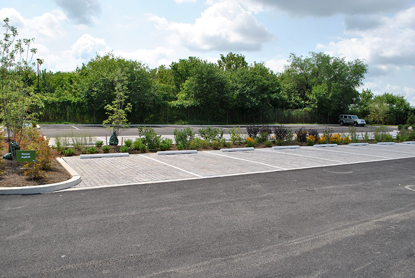
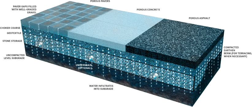
Porous pavement provides the structural support of conventional pavement, but allows stormwater to drain directly through the pavement surface into an underlying stone bed and the soil below, thereby reducing surface stormwater runoff. Porous pavement surfaces include, but are not limited to, porous asphalt, porous concrete, permeable pavers, reinforced turf, and artificial, or synthetic, turf. Interlocking pavers have openings filled with stone to create a porous surface. For all of these pavement types, stormwater flows through the porous surface during a rain event, then drains into the subbase beneath the pavement, where it is stored until it infiltrates into the soil.
Porous pavement can be combined with other SMPs in series to meet the Stormwater Regulations. The designer is referred to Section 3.2.3 for information on using SMPs in series.
Design of porous pavement is not limited to the examples shown within this text. Successful stormwater management plans will combine appropriate materials and designs specific to each site.
Quick Tip
Required porous pavement design and material standards are denoted in this Section by easy-to-reference numerals.
Porous pavement design may be considered differently for Stormwater Retrofits. Designers looking to incorporate porous pavement in Stormwater Retrofit projects should contact Stormwater Billing and Incentives for additional information.
When Can Porous Pavement Be Used?
Porous pavement is only suitable for select types of development. Porous pavements can be particularly well-suited for walkways, sidewalks, athletic surfaces, and playgrounds. Its footprint can be adapted to fit into spaces of almost any size and can be integrated into many different site layouts.
Porous pavement can be designed to meet the traffic loading requirements for most parking lots and travel surfaces, but the maintenance costs are significantly increased in areas that receive high traffic volume. For example, commercial parking lots will require more frequent vacuuming to prevent the pavement from clogging.
Key Advantages of Porous Pavement
- Can be used in place of traditional paved surfaces
- Can fit into spaces of almost any size and be integrated into many different site layouts
- Can be used as DIC to reduce DCIA as an alternative to traditional hardscape surfaces
- Reduces ponding and icing that can be associated with traditional hardscape surfaces
- Provides ancillary benefits such as better conditions for trees, reduced heat island effect, quieter vehicular traffic, and reduced vehicular glare compared to standard asphalt
- Permeable paver, reinforced turf, and artificial turf surface types are eligible for inclusion in an Expedited Post‑Construction Stormwater Management Plan (PCSMP) Review project
Key Limitations of Porous Pavement
- Not recommended for high traffic loading areas or on heavy industrial sites where vehicles or equipment may contribute heavy sediment or gross pollutant loads to porous surfaces
- Typically not suitable for steep slope applications
- Requires frequent maintenance with specialized equipment to maintain performance
- May degrade more rapidly if located in areas with frequent vehicular turning
Key Design Considerations for Porous Pavement
- Design of paving sections must consider system stability based on anticipated structural loading.
- Porous pavement should not be placed downstream of large impervious or pervious areas.
- Runoff from adjacent impervious and pervious areas must be conveyed directly to the subsurface storage to prevent clogging of porous surfaces.
- Porous pavement should not be used in areas where gasoline or other hazardous materials may be dispensed or handled.
- For any porous pavement structural SMP that discharges onto an adjacent property, a drainage easement may be required and is recommended.
Porous Pavement Types
Porous pavement systems can be distinguished by their intended stormwater management objective.
Porous pavement DIC systems are designed to receive and infiltrate direct (1:1) rainfall only and are considered as DIC. Infiltration testing is not required for porous pavement DIC; however, it is recommended to ensure timely drainage of the stone base. In some cases, where a small amount of run-on cannot be avoided, it may still be possible to consider the porous pavement disconnected. Such allowances will be considered on a case-by-case basis by PWD.
Porous pavement over a structural SMP is considered an SMP in series, where the porous pavement is designed to manage its direct (1:1) rainfall, and the structural SMP beneath it is designed to store and manage DCIA runoff from other areas on-site in addition to direct (1:1) rainfall onto the porous pavement atop the SMP. The porous surface cannot receive the additional runoff; The additional runoff must be conveyed directly to the underlying SMP. Porous pavement that receives direct overland flow is extremely prone to clogging. Porous pavement over a structural SMP is essentially a subsurface infiltration or detention system (based on infiltration feasibility) with a porous surface at-grade. The porous surface over the structural SMP footprint is considered DCIA. The structural SMP requires infiltration testing. The designer is referred to Section 3.3 for information on infiltration testing.
Porous pavement systems can also be distinguished by the type of porous paving surface. There are many different types of structural surfaces that allow water to flow through void spaces in the surface. Any of these alternatives serve as a form of conveyance and filtration for the storage bed below. Several of the most commonly used porous structural surfaces are described below, but this does not represent an exhaustive list of the porous surfaces appropriate for stormwater management applications.
Porous asphalt pavement consists of standard bituminous asphalt in which the fines have been screened and reduced, allowing water to pass through very small voids. Recent research in open-graded mixes for highway application has led to additional improvements in porous asphalt through the use of additives and binders. Porous asphalt is very similar in appearance to conventional, impervious asphalt.
Porous concrete is produced by substantially reducing the number of fines in the mix in order to establish voids for drainage. Porous concrete has a coarser appearance than its conventional counterpart.
Permeable pavers are typically interlocking units (often concrete) with openings that can be filled with a pervious material such as gravel. These units are often implemented for aesthetic reasons and are especially well suited to plazas, patios, residential driveways, and small parking areas. There are also plastic grids that can be filled with gravel to create a fully gravel surface that is not as susceptible to rutting and compaction as are traditional gravel lots. Gravel used in interlocking concrete pavers or plastic grid systems must be well-graded to ensure permeability.
Reinforced turf consists of interlocking structural units with openings that can be filled with soil for the growth of turf grass and are suitable for traffic loads and parking. They are often used in overflow or event parking. Reinforced turf grids can be made of concrete or plastic and are underlain by a stone and/or a sand drainage system for stormwater management. While both plastic and concrete units perform well for stormwater management and traffic needs, plastic units may provide better turf establishment and longevity, largely because the plastic will not absorb water and diminish soil moisture conditions.
Artificial or synthetic turf is a water permeable surface of synthetic fibers that emulates the aesthetic of natural grass. First gaining popularity in the 1960s, artificial turf has undergone a number of changes to its standard composition, with the most widely-used systems today featuring infills that are mixtures of sand and recycled (“crumb”) rubber. The designer is referred to Section 3.5.5 for more information on athletic turf fields.
4.2.2 Porous Pavement Components
Figure 4.2‑1: Porous Pavement with Typical Features
Pretreatment Component
Porous pavement does not typically have pretreatment systems due to its (1:1) loading ratio. Run-on from pervious or impervious areas is not permitted, so pretreatment is not necessary. However, any SMP installed beneath a porous pavement surface does require pretreatment of the runoff conveyed directly to it via piping.
Pretreatment systems capture trash, sediment, and/or pollutants from stormwater runoff before delivery to the storage or infiltration area. Pretreatment needs will vary significantly depending on the contributing drainage area composition and use. Pretreatment can include structures such as sumped and trapped inlets, sediment/grit chambers or separators, media filters, inlet inserts, or other appropriate prefabricated or proprietary designs to remove sediment, floatables, and/or hydrocarbons from stormwater runoff prior to being conveyed to a porous pavement structural SMP.
Pretreatment can also consist of filter strips, forebays, and swales. The designer is referred to Section 4.10 for more information on pretreatment systems.
Inlet Control Component
Porous pavement DIC systems, which receive direct (1:1) rainfall only, do not have inlet controls. For porous pavement over structural SMPs, inlet control systems convey and control the flow of stormwater from the contributing catchment area directly to the structural SMP.
Inlet control needs will vary depending on the design of stormwater conveyance systems and the site layout. The designer is referred to Section 3.4.2 for guidance on stormwater conveyance system design.
Inlet controls may include flow splitters, curbless design/curb openings, energy dissipaters, and inlets. The designer is referred to Section 4.11, Inlet Controls, for more information on inlet controls.
Storage Area Component
Storage areas within porous pavement DIC systems temporarily hold stormwater runoff as it infiltrates into native soils.
The subsurface storage component of a porous pavement structural SMP is typically constructed of a stone-filled, level-bottomed bed or trench, which may or may not incorporate pipes, arches, concrete vaults, crates, plastic grids, or other proprietary structures. The void spaces between the stones and/or structures store stormwater until it can infiltrate into the surrounding soils or be released downstream at a controlled rate.
Outlet Control Component
Outlet controls within a porous pavement structural SMP can provide a range of functions, including the following:
- Controlling how much water is stored for infiltration, if infiltration is feasible;
- Meeting drain down time requirements;
- Controlling the rate of discharge from the system and limiting water surface elevations during various storm events; and/or
- Bypassing of flows from large storm events.
Positive overflow must be provided for porous pavement. Positive overflow conveys runoff from larger storms out of the system and prevents flooding. In most cases, specifically for porous pavement DIC, appropriate grading of the porous surface is sufficient for providing positive flow away from porous pavemant should it become clogged or ineffective. For larger porous pavement systems or porous pavement over a structural SMP, inlets are the most common overflow. A perforated pipe system can convey water from the storage bed, but static storage for the Water Quality Volume (WQv) is required below the perforated pipes.
Outlet controls may include orifices, weirs, or underdrains. The designer is referred to Section 4.12 for more information on outlet controls.
Inspection and Maintenance Access Component
Safe and easy inspection and maintenance access to all major components within porous pavement is critical to ensuring long-term performance. Inspection and maintenance access structures provide a portal to any structural SMP beneath the porous pavement. Access points provide access to subsurface systems, both for inspections and routine maintenance, and for pumping water out of subsurface systems in cases of failure or severe damage. Manholes provide access for maintenance personnel and equipment to perform maintenance and inspections. Cleanouts provide access for hoses and vacuum equipment, as well as for any installed underdrains. Observation wells provide access to the bottom of subsurface systems for performance inspections and monitoring. Access structures may also serve additional functions, such as joining subsurface pipes.
4.2.3 Porous Pavement Design Standards
General Design Standards
- For porous pavement DIC systems:
- A reduction in DCIA is permitted when a porous pavement system is installed on-site such that it does not create any areas of concentrated infiltration or discharge.
- The surface slope in any direction across porous pavement cannot exceed 5% to be eligible for disconnection credit.
- The choker course depth must be a minimum of two inches.
- If an underdrain is proposed, the porous pavement will only be considered DIC if the first 1.5 inches of runoff can be stored below the lowest invert of the underdrain.
- Appropriate Curve Number (CN) values must be used when performing Flood Control calculations.
- For porous pavement over a structural SMP, if infiltration is feasible, the designer is referred to Section 4.4, Subsurface Infiltration, for subsurface infiltration general design requirements.
- For porous pavement over a structural SMP, if infiltration is infeasible, the designer is referred to Section 4.8, Subsurface Detention, for subsurface detention general design requirements.
Pretreatment Design Standards
- Acceptable form(s) of pretreatment must be incorporated into design. Pretreatment of runoff from all inlets is required. At a minimum, this can be achieved through the use of sumps and traps for inlets, and sump boxes with traps downstream of trench drains. The designer is referred to Section 4.10, Pretreatment, for more information on design standards for pretreatment systems.
Inlet Control Design Standards
- The designer is referred to Section 4.11, Inlet Controls, for information on design standards for inlet control systems.
Storage Area Design Standards
- For porous pavement DIC systems:
- Stone storage bed depth must be a minimum of eight inches, except when located beneath walkways or play surfaces, for which a depth of four inches is allowable.
- Stone must be separated from soil media by a separation barrier, such as a geotextile or a pea gravel filter, to prevent sand, silt, and sediment from entering the system.
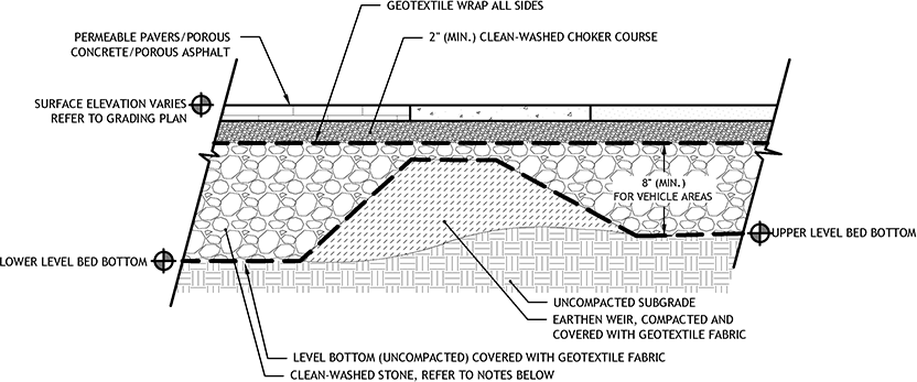
- Stone storage systems must have a level bottom. Terraced systems may be used to maintain a level infiltration interface with native soil while accommodating significant grade changes.
- For porous pavement over a structural SMP, if infiltration is feasible, the designer is referred to Section 4.4, Subsurface Infiltration, for subsurface infiltration storage area requirements.
- For porous pavement over a structural SMP, if infiltration is infeasible, the designer is referred to Section 4.8, Subsurface Detention, for subsurface detention storage area requirements.
- When SMPs are used in series, the storage areas for all SMPs must provide cumulative static storage for the WQv, but there is no minimum storage requirement for each individual SMP used in series.
Outlet Control Design Standards
- Impervious liners beneath porous pavement should be avoided, but they may be necessary in areas over tunnels or subsurface structures. The lined area should be a minimal portion of the total porous area. If a significant area needs to be lined, porous pavement may not be an appropriate management strategy.
- Underdrains, if proposed for porous pavement DIC systems, must meet the following requirements:
- Underdrains must be surrounded by a sand or stone layer to filter sediment and facilitate drainage.
- The minimum allowable thickness of a sand or stone filter layer is six inches both above and beneath the underdrain.
- To prevent clogging, underdrain pipes must be surrounded by a geotextile fabric if a sand layer is used.
- Inlets or area drains must be provided for all porous pavement areas in excess of 5,000 square feet, in order to provide positive overflow.
- The designer is referred to Section 4.12, Outlet Controls, for information on design standards for outlet control systems.
Inspection and Maintenance Design Standards for Porous Pavement Over a Structural SMP
- Cleanouts, manholes, access panels and other access features must be provided to allow unobstructed and safe access to SMPs for routine maintenance and inspection of inflow, outflow, underdrains, and storage systems.
- Observation wells must be provided for storage systems that include stone storage and must meet the following requirements:
- The observation well must be placed at the invert of the stone bed.
- An observation well must be located near the center of the stone bed system to monitor the level and duration of water stored within the system (drain down time).
- Adequate inspection and maintenance access to the observation well must be provided.
- A manhole may be used in lieu of an observation well if the invert of the manhole is installed at or below the bottom of the SMP and the manhole is configured in such a way that stormwater can flow freely between the SMP and the manhole at the SMP’s invert.
- Access features for underground storage systems
- Access features must be provided for all underground storage systems that are not stone storage beds.
- A sufficient number of access points in the system must be provided to efficiently inspect and maintain the storage area.
- For cast-in-place vault systems, access features must consist of manholes or grated access panels or doors. Grated access panels are preferred to maintain airflow.
- For grid storage or other manufactured systems, follow the manufacturer’s recommendations.
- Ladder access is required for vaults greater than four feet in height.
- Header pipes, at minimum 36-inch diameter, connected to manholes at each corner of the subsurface system must be provided. Alternatively, smaller header pipes may be used if cleanouts are provided on the manifold/header pipe junction for each distribution pipe. The cleanouts must be on alternating sides of the SMP.
Figure 4.2‑2: Porous Pavement Standard Detail
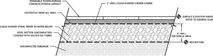
Figure 4.2‑3: Terraced Porous Pavement Standard Detail
4.2.4 Porous Pavement Material Standards
Pretreatment Material Standards
- The designer is referred to Section 4.10, Pretreatment, for information on materials standards for pretreatment systems.
Inlet Control Material Standards
- Porous Bituminous Asphalt
- Bituminous surface must be laid with a bituminous mix of 5.75% to 6% by weight dry aggregate.
- In accordance with American Society of Testing and Materials (ASTM) D6390, drain down of the binder must be no greater than 0.3%.
- Aggregate material in the asphalt must be clean, open-graded, and a minimum of 75% fractured with at least one fractured face by mechanical means of each individual particle larger than 0.25 inch, and it must have the following gradations:
Table 4.2‑1: Porous Asphalt Binder Course Aggregate Gradation
| U.S. Standard Sieve Size | Percent Passing By Weight |
|---|---|
| 1″ | 100% |
| 3/4″ | 90-100% |
| 1/2″ | 80-100% |
| 3/8″ | 50-80% |
| #4 | 10-20% |
| #8 | 5-10% |
| #40 | 3-8% |
| #200 | 0-3% |
Table 4.2‑2: Porous Asphalt Wearing Course Aggregate Gradation
| U.S. Standard Sieve Size | Percent Passing By Weight |
|---|---|
| 5/8″ | 100% |
| 1/2″ | 95-100% |
| 3/8″ | 70-95% |
| #4 | 20-40% |
| #8 | 10-20% |
| #40 | 0-8% |
| #200 | 0-3% |
-
- Neat asphalt binder modified with an elastomeric polymer to produce a binder meeting the requirements of PG 76-22 as specified in American Association of State Highway and Transportation Officials (AASHTO) MP-1. The elastomer polymer must be styrene-butadiene-styrene, or approved equal, applied at a rate of 3% by weight of the total binder.Hydrated lime should be added at a dosage rate of 1% by weight of the total dry aggregate to mixes containing granite.
- Hydrated lime must meet the requirements of ASTM C 977.The additive must be able to prevent the separation of the asphalt binder from the aggregate and achieve a required tensile strength ratio of at least 80% on the asphalt mix when tested in accordance with AASHTO T 283.
- The asphaltic mix must be tested for its resistance to stripping by water in accordance with ASTM D-1664.
- The additive must be able to prevent the separation of the asphalt binder from the aggregate and achieve a required tensile strength ratio of at least 80% on the asphalt mix when tested in accordance with AASHTO T 283.
- The asphaltic mix must be tested for its resistance to stripping by water in accordance with ASTM D-1664.
- If the estimated coating area is not above 95%, anti-stripping agents must be added to the asphalt.
- Porous Concrete
- Porous concrete must use Portland Cement Type I or II conforming to ASTM C 150 or Portland Cement Type IP or IS conforming to ASTM C 595.
- Aggregate must be No. 8 coarse aggregate (3/8-inch to No. 16) per ASTM C 33 or No. 89 coarse aggregate (3/8-inch to No. 50) per ASTM D 448.
- An aggregate/cement ratio range of 4:1 to 4.5:1 and a water/cement ratio range of 0.34 to 0.40 should produce porous pavement of satisfactory properties in regard to permeability, load carrying capacity, and durability characteristics.
- Permeable Paver and Grid Systems
- Permeable paver and grid systems must conform to manufacturer specifications.
- The systems must have a minimum flow through rate of five inches per hour and a void percentage of no less than 10%.
- Gravel used in interlocking concrete pavers or plastic grid systems must be well-graded and washed to ensure permeability.
- The designer is referred to Section 4.11, Inlet Controls, for information on material standards for inlet control systems.
Storage Area Material Standards
- Stone
- Stone designed for stormwater storage must be uniformly graded, crushed, clean-washed stone. PWD defines “clean-washed” as having less than 0.5% wash loss, by mass, when tested per AASHTO T-11 wash loss test. AASHTO No. 3 and No. 57 stone can meet this specification.
- All aggregates used within a porous pavement system must meet the following requirements:
- Maximum wash loss: 0.5% per AASHTO T-11
- Minimum durability index: 35 per ASTM D3744
- Maximum abrasion: 10% for 100 revolutions and 50% for 500 revolutions per ASTM C131
- All choker course aggregate must meet the specifications of AASHTO No. 57 and must meet the following gradation:
Table 4.2‑3: Required Choker Course Gradation
| U.S. Standard Sieve Size | Percent Passing By Weight |
|---|---|
| 1 ½” (37.5 mm) | 100% |
| 1” (25 mm) | 95-100% |
| ½” (19 mm) | 25-60% |
| #4 (4.75 mm) | 0-10% |
| #8 (2.36 mm) | 0-5% |
- Sand, if used, must be AASHTO M-6 or ASTM C-33 sand and must have a grain size of 0.02 to 0.04 inches.
- Storage Chambers (For Porous Pavement Structural SMPs)
- Pipe used within a subsurface infiltration SMP must be continuously perforated and have a smooth interior with a minimum inside diameter of four inches.
- High-density polyethylene (HDPE) pipe must meet the specifications of AASHTO M252, Type S or AASHTO M294, Type S.
- Any pipe materials outside the SMP are to meet City Plumbing Code Standards.
- Geotextile must consist of polypropylene fibers and meet the following specifications (AASHTO Class 1 or Class 2 geotextile is recommended):
- Grab Tensile Strength (ASTM-D4632): ≥ 120 lbs
- Mullen Burst Strength (ASTM-D3786): ≥ 225 psi
- Flow Rate (ASTM-D4491): ≥ 95 gal/min/ft2
- UV Resistance after 500 hrs (ASTM-D4355): ≥ 70%
- Heat-set or heat-calendared fabrics are not permitted.
Outlet Control Material Standards
- Underdrains, if proposed, must be made of continuously perforated HDPE plastic piping with a smooth interior and a minimum inner diameter of four inches. HDPE pipe must meet the specifications of AASHTO M252, Type S or AASHTO M294, Type S.
- The designer is referred to Section 4.12, Outlet Controls, for information on material standards for outlet control systems.
Inspection and Maintenance Access Material Standards
- Observation wells must consist of perforated plastic pipe with a minimum inner diameter of six inches.
- Cleanouts must be made of material with a smooth interior having a minimum inner diameter of four inches. The diameter of the cleanout must match the diameter of its connecting pipe up to eight inches. If the pipe is larger than eight inches in diameter, then the cleanout must be eight inches in diameter.
4.2.5 Porous Pavement Construction Guidance
The construction guidelines herein apply to all porous pavement systems, with additional guidance provided specifically for porous asphalt. Proper construction and careful consideration of soil compaction, infiltration performance, and sedimentation control of subsurface infiltration systems are essential to ensure long-term functionality and reduce long-term maintenance needs. Since subsurface infiltration systems are, by definition, buried, construction oversight is critical. At a minimum, verification of volumes, grades, and elevations must be confirmed prior to backfill.
- Areas for porous pavement systems must be clearly marked before any site work begins to avoid soil disturbance and compaction during construction.
- Excavate porous pavement subsurface area to proposed depth. Excavation should take place after contributing upstream disturbed areas have been permanently stabilized. If this is impractical, install PWD-approved erosion and sedimentation control Best Management Practices (BMPs) to prevent runoff and sediment from entering the excavated bed. Where erosion of subgrade has caused accumulation of fine materials and/or surface ponding, this material must be removed with light equipment and the underlying soils scarified to a minimum depth of six inches with a York rake or equivalent and light tractor.
- Existing subgrade must not be compacted and construction equipment traffic must be minimized prior to placement of the geotextile and stone bed. The use of machinery to load stone from outside of the basin footprint is recommended. If it is essential that equipment be used in the excavated area, all equipment must be approved by the engineer. Equipment with narrow tracks or tires, rubber tires with large lugs, or high pressure tires will cause excessive compaction and must not be used. Should the subgrade be compacted during construction, additional testing of soil infiltration rates and system redesign may be required. Rock construction entrances must not be located on top of areas proposed for infiltration practices.
- Bring subgrade of stone infiltration bed to line, grade, and elevations indicated in the drawings, while avoiding compaction. The bottom of the infiltration bed must be at a level grade.
- Place geotextile and recharge bed aggregate immediately after approval of subgrade preparation to prevent accumulation of debris or sediment. Aggregate installation should take place after contributing upstream disturbed areas have been permanently stabilized. Install PWD-approved erosion and sedimentation control BMPs to prevent runoff and sediment from entering the storage bed during the placement of the geotextile and aggregate bed.
- Place geotextile in accordance with manufacturer’s standards and recommendations. Adjacent strips of filter fabric must overlap a minimum of 16 inches. Fabric must be secured at least four feet outside of bed. This edge strip should remain in place until all bare soils contiguous to beds are stabilized and vegetated. As the site is fully stabilized, excess geotextile can be cut back to the edge of the bed.
- Install aggregate course in lifts of six to eight inches. Compact each layer with equipment, keeping equipment movement over storage bed subgrades to a minimum. Install aggregate to grades indicated on the drawings.
- Additional Construction Guidelines for Installation of Porous Asphalt:
- Install and compact choker course aggregate evenly over surface of stone bed. Choker base course must be sufficient to allow for even placement of asphalt, but no less than two inches in depth.
- Vehicles with smooth, clean dump beds must be used to transport the asphalt mix to the site. Control cooling of asphalt by covering mix. Porous asphalt mix must not be stored for more than 90 minutes before placement.
- The porous bituminous surface course must be laid in one lift directly over the storage bed and stone base course.
- Compaction of the surface course must take place when the surface is cool enough to resist a ten-ton roller. One or two passes is all that is required for proper compaction. More rolling could cause a reduction in the surface porosity and permeability, which is unacceptable.
- After rolling asphalt, no vehicular traffic is permitted on the surface until cooling and hardening has taken place (minimum 48 hours).
- After hardening, test hydrologic performance of the pavement surface by applying clean water to a single location at the surface at a rate of at least five gallons per minute. The water applied to the surface should readily infiltrate without creating puddles or runoff.
- Do not use the porous pavement area for equipment or materials storage. No soil must be deposited on porous pavement surfaces.
4.2.6 Porous Pavement Maintenance Guidance
Maintenance of porous pavement systems focuses on the periodic removal of sediment and debris from the porous surfaces. General recommended maintenance activities for porous pavement are summarized in Table 4.2‑4.
Table 4.2‑4: Porous Pavement Maintenance Guidelines
| Early Maintenance Activity | Frequency |
|---|---|
| Inspect erosion control and flow spreading devices until soil settlement and vegetative establishment of contributing areas has occurred. | Biweekly |
| Ongoing Maintenance Activity | Frequency |
|---|---|
| Inspect erosion control and flow spreading devices until soil settlement and vegetative establishment of contributing areas has occurred. | Biweekly |
| Mow grass in permeable paver or grid systems that have been planted with grass. | As Needed |
| Vacuum porous asphalt or concrete surfaces with regenerative air sweeper or commercial vacuum sweeper (traditional street sweepers are not appropriate). | Semiannually |
| Clean out inlet structures within or draining to the structural SMP beneath the porous pavement surface. | Semiannually |
| Inspect underdrain cleanouts, if any. | Semiannually |
| Maintain records of all inspections and maintenance activity. | Ongoing |
Sediment Control
Superficial soil does not necessarily clog the voids in porous surfaces. However, soil that is ground in repeatedly by tires can lead to clogging. Therefore, trucks or other heavy vehicles should be prevented from tracking or spilling soil onto the pavement. Furthermore, all construction or hazardous materials carriers should be prohibited from entering a porous pavement lot. Areas with heavy vehicular traffic will require more frequent vacuuming.
Winter Maintenance
Winter maintenance for a porous pavement may be necessary, but is usually less intensive than that required for a standard asphalt lot. By its very nature, a porous pavement system with subsurface aggregate bed may have better snow and ice melting characteristics than standard pavement. Once snow and ice melt, they flow through the porous pavement rather than refreezing. Therefore, ice and light snow accumulation are generally not as problematic. However, snow will accumulate during heavier storms. Abrasives such as sand or cinders must not be applied on or adjacent to the porous pavement. Snow plowing is acceptable, provided it is done carefully (i.e., by setting the blade about 0.5 inches higher than usual and using a rubberized blade or blade tip). Salt is acceptable for use as a deicer on the porous pavement, though non-toxic, organic deicers, applied either as blended, magnesium chloride-based liquid products or as pretreated salt, are preferable. Any deicing materials should be used in moderation.
Repairs
Potholes are not common; though settling might occur if a soft spot in the subgrade is not removed during construction. Damaged areas that are smaller than 50 square feet and comprising less than 10% of the total porous area can be patched with a porous or standard asphalt mix, depending on the location within the porous area. In many cases the loss of porous surface will be insignificant. If an area greater than 50 square feet or 10% of the total is in need of repair, approval of patch type must be sought from either the engineer or owner. Porous pavement must never be seal coated under any circumstances. Any required repair of drainage structures should be done promptly to ensure continued proper functioning of the system.
Outlet Controls
The designer is referred to Section 4.12, Outlet Controls, for information on maintenance guidance for outlet controls.