After exhausting options for using non-structural design and disconnected impervious cover (DIC), the designer is required to evaluate and document infiltration feasibility when using stormwater management practices (SMPs) as a strategy to comply with the Philadelphia Water Department (PWD) Stormwater Regulations (Stormwater Regulations) or applicable stormwater management design standards. If infiltration is deemed feasible, the designer must use infiltration SMPs, such as bioinfiltration basins, to comply with the Water Quality requirement. If infiltration is not feasible, the designer must document justification for this condition (Section 3.3.6) via the Online Technical Worksheet (Section 3.4.3) and use acceptable pollutant-reducing SMPs to comply with the Water Quality requirement (Section 1.2.1) if required to comply with Stormwater Regulations. A slow release rate requirement associated with the Water Quality requirement is applicable only to non-infiltrating areas in combined sewersheds for both Development and Stormwater Retrofit project types. Efforts to maximize development potential should not preclude the use of infiltration SMPs.
This Section details the infiltration testing and soil assessment procedures required for the selection and detailed design of SMPs. If conceptual SMP locations and footprint areas have not yet been determined, the designer should return to Sections 3.1 and 3.2 for guidance on conceptual SMP design. PWD recommends that preliminary soil analyses and infiltration testing be completed during the conceptual SMP design phase. This is strongly recommended because the results can be used as a planning tool for identifying areas that are favorable for the construction of infiltration SMPs, and for more thorough investigations. If seeking Stormwater Grant funding for a Stormwater Retrofit project, the designer should review the Stormwater Grants Application Guide for guidance on the minimum testing required for a Stormwater Grant Application Conceptual Stormwater Management Plan. The designer should use the guidance below to further inform their Post‑Construction Stormwater Management Plan (PCSMP) design.
As a reminder, locating conceptual infiltration SMP footprint areas should be avoided in the following locations identified during the site assessment process (Section 3.1.1 and Section 3.1.2). A number of these scenarios will require further investigation before determining infiltration feasibility and SMP layout.
- Areas with previously documented high seasonal groundwater or located in the floodplain;
- Areas with previously documented shallow bedrock, clay, hydrologic soil group “D” soils, or other limiting soil layers;
- Areas within existing rights-of-way and easements;
- Areas that do not achieve the minimum required ten-foot setback from all existing and proposed buildings and neighboring properties; and
- Documented hotspots.
For projects where infiltration is not feasible due to full build-out designs (where ground-level space is not available in the proposed site layout), infiltration testing may not be required. For these scenarios, the applicant must request a waiver from the infiltration requirement (Section 3.3.6) via the Online Technical Worksheet (Section 3.4.3). The applicant is encouraged to contact PWD Stormwater Plan Review prior to initial plan submission to confirm the full build-out design is eligible for a waiver from infiltration.
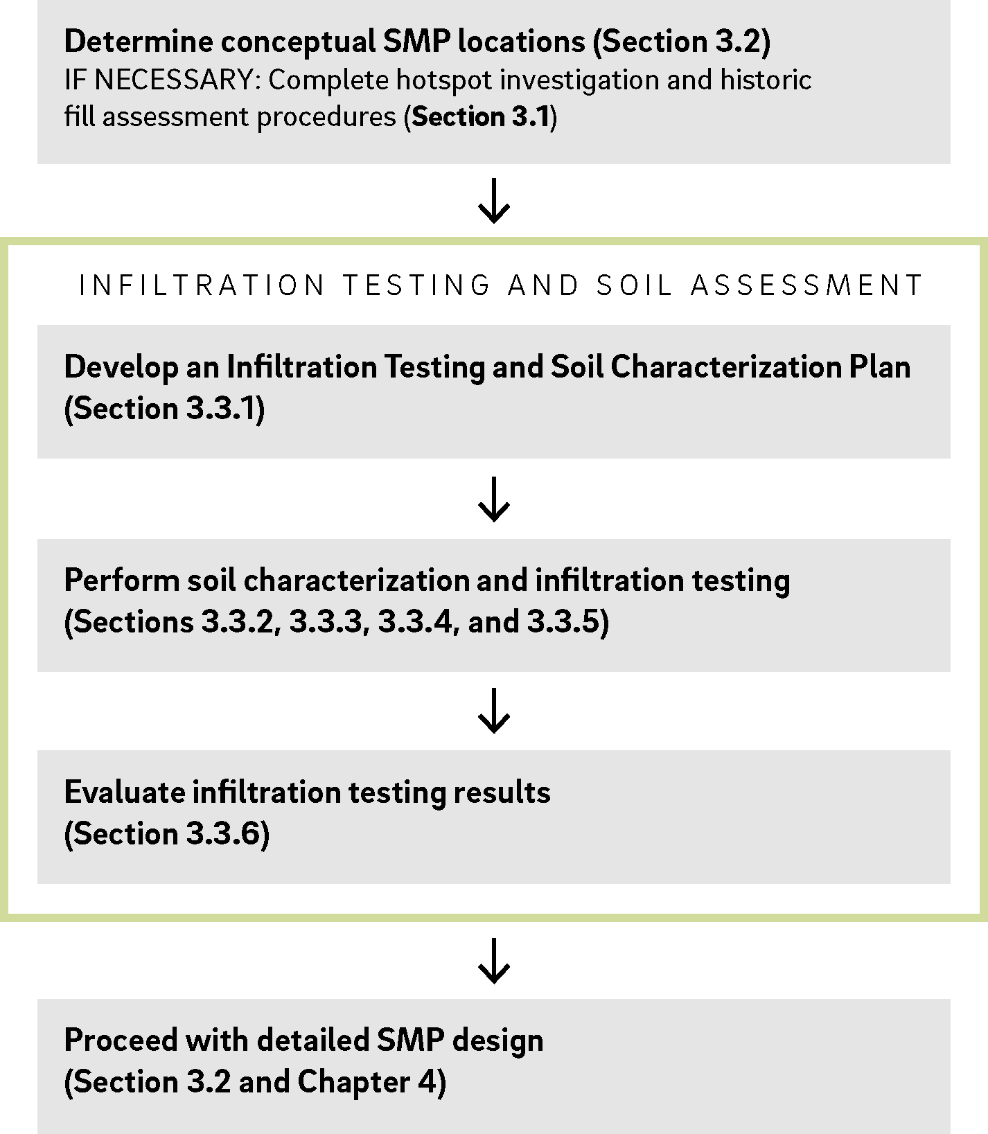
After conceptual SMP locations have been determined for the project site, the designer must complete the infiltration testing and soil assessment process illustrated in Figure 3.3‑1. Each step of this process is described within the following Sections.
Figure 3.3‑1: Infiltration Testing and Soil Assessment Process for SMP Design
If required, infiltration testing and soil characterization must be completed before the PCSMP Review Phase, unless the project is deemed eligible for an Expedited PCSMP Review. The designer is referred to Section 2.3 and Section 2.4 for descriptions and requirements related to Review Phases and Expedited PCSMP Reviews, respectively.
3.3.1 Infiltration Testing and Soil Characterization Plan Development
Prior to conducting infiltration testing and soil characterization at the project site, the designer must prepare an Infiltration Testing and Soil Characterization Plan (Testing Plan). This Testing Plan is a required element of the Geotechnical Report (Section 3.3.6). The Testing Plan must reflect the most up-to-date proposed SMP footprints at the time of testing.
The Testing Plan must be developed to meet the requirements within this Chapter and, at a minimum, must indicate the following information:
- Location and SMP identifier of all proposed SMPs, each labeled with the following information:
- Proposed infiltration footprint area,
- Type of SMP proposed, and
- Proposed infiltration interface (SMP bottom) elevation.
- Location of all proposed test pits, soil borings, and infiltration tests, each labeled with the following information:
- Number of tests proposed based on the requirements provided within this Section;
- Type of test(s) proposed (test pit, soil boring, double-ring infiltrometer, cased borehole infiltration test);
- Depth of testing for each test, relative to existing ground surface elevations, based on the requirements provided within this Section; and
- Dimensions from parcel boundaries and/or existing structures.
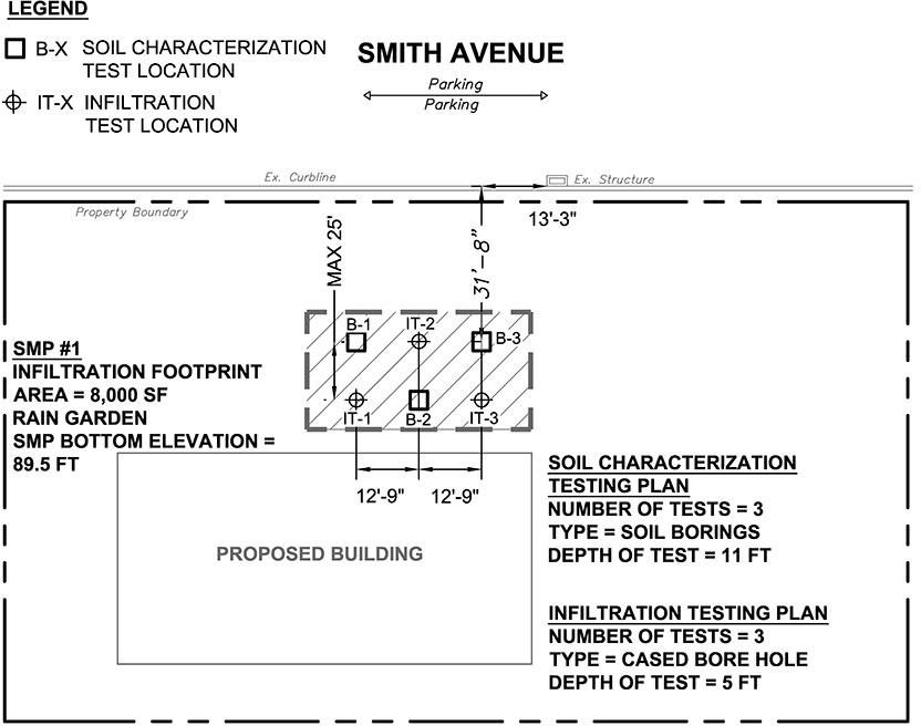
An example Testing Plan is included as Figure 3.3‑2. This figure is generic and does not represent the required density or spacing of tests as documented within this Section, but demonstrates how to illustrate the minimum Testing Plan requirements described above. The hatched rectangle delineating the proposed SMP location and proposed test locations are dimensioned from a fixed object (e.g., an existing inlet within the public right-of-way).
Figure 3.3‑2: Example Infiltration Testing and Soil Characterization Plan
The designer must adhere to the soil characterization requirements in Section 3.3.2 and the infiltration testing requirements in Section 3.3.3 when creating the Testing Plan. Prior to conducting geotechnical testing the appropriate density, type, and spacing for each test must be determined using the requirements provided.
3.3.2 Soil Characterization Requirements
Soil characterization and limiting layer identification provides a visual assessment of the soil profile that is supplemental to infiltration testing results. Understanding the characteristics of soils in which infiltration testing is conducted provides the designer with better insight into the testing results and feasibility of installing an infiltrating SMP at the project site.
The presence of limiting layers such as groundwater, bedrock, or impermeable soils within two vertical feet of the infiltration footprint of an SMP is prohibited. The presence of bedrock or impermeable soils in relatively close proximity to the infiltration interface may result in lateral, as opposed to vertical, infiltration if the rock is not sufficiently jointed and/or fissured to infiltrate. This can result in water migrating to, and emerging within, topographically low areas. The presence of groundwater in close proximity to the infiltration interface could increase the potential for groundwater mounding. Further characterization of subsurface soils can provide information on the underlying site conditions or evidence of limiting layers below the infiltration interface. Therefore, PWD requires that soil excavations be performed beyond the proposed infiltration interface (SMP bottom) elevation. As testing progresses, the testing professional must document the presence of any limiting layers, groundwater presence, and in situ observations of soil characteristics. PWD also requires soil sampling for laboratory soil classification to further supplement infiltration testing results.
Acceptable soil characterization testing methods are as follows:
- Exploratory Test Pits, and
- Hollow-Stem Augered Boreholes (Soil Borings).
These soil characterization methods must be conducted in conjunction with the required soil sampling.
An exploratory test pit allows visual observation of the soil horizons and overall soil conditions both horizontally and vertically in that portion of the site. Test pit observations can be made across a site at a relatively low cost and in a short period of time. When soil borings are performed, the soil horizons cannot be observed in situ, but must be observed from the extracted borings. As a result, visual observation is narrowly limited in a soil boring. As such, test pits are strongly recommended over soil borings unless conditions are present that render the excavation of test pits impractical (e.g., existing structures, utilities, space constraints, depth of test, etc.).
Key requirements for the two acceptable soil characterization methodologies and accompanying soil sampling are summarized below.
Test Pits
- For projects with 15,000 square feet or more of earth disturbance, a minimum of two test pits must be completed for each SMP footprint. For projects with less than 15,000 square feet of earth disturbance, a minimum of one test pit must be completed for each SMP footprint.
- Test pits are required in order to conduct double-ring infiltrometer testing.
- At least one test pit for each SMP must be excavated to a minimum depth of four feet below the proposed infiltration interface of the SMP, which is the lowest elevation where infiltration is proposed (the SMP bottom elevation), or until bedrock or fully saturated conditions are encountered. When conditions prevent the over-excavation of test pits to the minimum required depth, soil borings, in addition to the under-excavated test pits, should be used in conjunction with double-ring infiltrometer testing to provide soil classification down to the required depths.
- Where test pits are greater than five feet deep, appropriate sloping and benching must be provided for access and infiltration testing, as necessary, in accordance with Occupational Safety and Health Administration (OSHA) Regulations (Part 1926, Subpart P – Excavations, Standard Number 1926.652 Requirements for Protective Systems).
Soil Borings
- A hollow-stem augered borehole should be used for soil classification when site constraints do not allow for a test pit (e.g., the proposed SMP footprint is located in an area with existing structures or utilities present, or the depth to the infiltration interface does not allow for a benched excavation with site constraints).
- A minimum of one soil boring should be conducted for each cased borehole infiltration test.
- All soil borings must be advanced to a depth of ten feet below the SMP bottom elevation or until auger refusal with continuous split spoon sampling.
- Hollow-stem augered borehole soil characterization studies must not be completed within the same hole as the infiltration testing, but the boreholes must be located no less than five feet, and no more than ten feet, away from the infiltration test locations.
- Drilling and sampling procedures must be in accordance with the Hollow-Stem Auger Method (American Society of Testing and Materials (ASTM) standard D6151-08) with a minimum four-inch inner tube diameter.
- Standard Penetration Tests (SPTs) must be in accordance with ASTM D1586 (Standard Test Method for SPT and Split-Barrel Sampling of Soils). Blow count data must be collected from the soil samples.
Soil Sampling
- PWD requires that three soil samples be taken per acre of SMP footprint area, with a minimum of one soil sample per SMP.
- At least one soil sample must be taken as close to the infiltrating interface (SMP bottom elevation) as possible, within one vertical foot.
- The designer is also required to obtain a soil sample from the location of an infiltration test and conduct a sieve analysis of the sample.
- Soil samples must be obtained during the soil characterization field analysis and classified according to ASTM D2487 (Standard Practice for Classification of Soils for Engineering Purposes [Unified Soil Classification System]) and ASTM D2488 (Standard Practice for Description and Identification of Soils [Visual-Manual Procedure]).
- Soil samples must undergo laboratory particle size analysis according to ASTM D422-63 (Standard Test Method for Particle-Size Analysis of Soils) down to the No. 200 sieve.
- Split spoon sampling must be completed in accordance with ASTM D1586 (Standard Test Method for SPT and Split-Barrel Sampling of Soils). Blow count data must be collected from the soil samples.
3.3.3 Infiltration Testing Requirements
All tests must be performed within 25 horizontal feet of each infiltration area. At least one infiltration test must be conducted as close to the proposed infiltration interface (SMP bottom elevation) as possible within one vertical foot. More tests may be warranted if the results of the first three tests vary significantly. Testing locations should be evenly distributed. Infiltration tests may be used for the design of multiple SMPs as long as the minimum requirements are met for each SMP. Follow-up testing may be required if the location or elevation of any SMPs change in such a way that the infiltration testing previously performed in the area of that SMP no longer meets PWD’s proximity, elevation, and density requirements. It is the designer’s responsibility to contact PWD Stormwater Plan Review or Stormwater Billing and Incentives regarding the need for follow-up testing for a project. Each test must be accompanied by either a test pit or soil boring.
Acceptable infiltration testing methodologies consist of:
- Double-Ring Infiltrometer Tests with Test Pits, and
- Cased Borehole Tests with Soil Borings.
The main difference between the two methods is that a double-ring infiltrometer test estimates the vertical movement of water through the bottom of the test area using a larger surface area than a cased borehole infiltration test. The double-ring infiltrometer testing apparatus consists of two concentric metal rings that are driven into the ground and filled with water. The outer ring helps to reduce lateral movement of water in the soil (typically 12 to 24 inches in diameter) while the inner ring is used to calculate an infiltration rate (typically six to 12 inches in diameter). The cased borehole test uses an outer casing (typically four inches in inner diameter) to prevent lateral movement of water through soil. The procedures of these test methods are provided in Section 3.3.5.
While both testing methods are allowed, PWD strongly prefers the use of double-ring infiltrometer testing where space permits. Because test pits are required to perform double-ring infiltrometer tests, the applicant must first determine whether test pits are feasible (Section 3.3.2). If test pits are feasible, then the designer should develop the Testing Plan to meet the minimum requirements for double-ring infiltrometer tests and test pits. If conditions render the excavation of test pits impractical, due to existing structures, utilities, space constraints, depth of test, etc., the designer should first document the condition(s), and then develop the Testing Plan to meet the requirements of cased borehole tests and soil borings. Soil borings may be used in lieu of over-excavating test pits where space constraints exist.
Key requirements for the two acceptable infiltration testing methodologies are summarized below.
Double-Ring Infiltrometer Test
- Five infiltration tests must be performed per acre of SMP footprint, or one test per 8,712 square feet, and a minimum of three tests must be performed.
- The diameter of the inner ring must be no less than six inches.
- Test pits are required in order to conduct double-ring infiltrometer tests. A maximum of two double-ring infiltration tests can be conducted within the same test pit.
- Test holes must be presoaked for one hour immediately prior to testing. The presoaking procedure is intended to simulate saturated conditions in the environment and to minimize the influence of unsaturated flow.
- Testing must be conducted for a minimum of eight readings or until a stabilized infiltration rate is measured. A stabilized rate of drop means a difference of 0.25 inch or less of drop between the highest and lowest readings of four consecutive readings.
- The designer is referred to the infiltration testing procedure information provided in Section 3.3.5 for further double-ring infiltrometer testing guidance.
Cased Borehole Test
- Infiltration tests must not be completed within the same borehole as hollow-stem augered borehole soil characterization studies, but must be completed no less than five feet, and no more than ten feet, away from the soil characterization borehole locations.
- Eight infiltration tests must be performed per acre of SMP footprint, or one test per 5,445 square feet, and a minimum of three tests must be performed.
- The casing installation must be completed using ASTM D6151-08 – Hollow-Stem Auger Method, with the inner diameter of the pipe being no less than four inches.
- Only one infiltration test is acceptable for each borehole, regardless of whether tests are proposed to be completed at different depths.
- Test holes must be presoaked for one hour immediately prior to testing. The presoaking procedure is intended to simulate saturated conditions in the environment and to minimize the influence of unsaturated flow.
- Testing must be conducted for a minimum of eight readings or until a stabilized infiltration rate is measured. A stabilized rate of drop means a difference of 0.25 inch or less of drop between the highest and lowest readings of four consecutive readings.
- The designer is referred to the infiltration testing procedure information provided in Section 3.3.5 for further cased borehole testing guidance.
3.3.4 Soil Characterization Procedures
Soil characterization and limiting layer identification provides a visual assessment of the soil profile, which can support supplemental infiltration testing results. PWD allows the use of exploratory test pits or soil borings to assess soil for infiltration feasibility; however, PWD strongly prefers the use of test pits where space allows. With both methods, soil sampling and characterization are required. Requirements for each soil characterization and soil sampling method are described in Section 3.3.2, while procedures are described below.
Exploratory Test Pit Procedure
A test pit consists of a backhoe-excavated trench, of an appropriate width, with the goal of exposing a soil profile. As the excavation progresses, the testing professional must document the presence of any limiting layers, groundwater presence, and in situ observations of soil characteristics. When test pits are the chosen soil characterization methodology, the double-ring infiltrometer method must be used as the infiltration testing methodology. The designer is referred to Appendix H for a blank Infiltration Testing Log, which is required to be completed and submitted as part of the Geotechnical Report and includes guidance for documenting soil characteristics. Soil classifications must be conducted in accordance with ASTM D2488. The designer is referred to Section 3.3.5 for the double-ring infiltrometer testing procedure.
Hollow-Stem Augered Borehole Procedure
A hollow-stem augered borehole soil characterization can be performed where space constraints prevent the excavation of test pits. The test is completed using a four-inch inner diameter or larger hollow-stem auger. The designer is referred to Appendix H for a blank Infiltration Testing Log, which is required to be completed and submitted as part of the Geotechnical Report and includes guidance for documenting soil characteristics. Soil classifications must be conducted in accordance with ASTM D2488. Blow counts, if the designer and geotechnical professional elect to perform SPTs, must be performed in accordance with ASTM D1586. As the test progresses, the testing professional must document the presence of any limiting layers, groundwater presence, and in situ observations of soil characteristics (Soil Sampling Requirements and Procedure Sections are listed below). The ASTM standard D6151-08, Hollow-Stem Auger Method, should be referenced for specific direction, but the general testing procedure is as follows:
- Advance a borehole to the proposed testing depth using the Hollow-Stem Auger Method (ASTM D6151-08). The augered hole diameter must be at least two inches larger than the outer diameter of the inner casing. The inner casing will consist of a PVC pipe with a minimum inner diameter of four inches and a smooth, square bottom.
- Push the inner casing within the auger hollow stem to the infiltration interface and firmly set it into the bottom of the borehole. Use a borehole plane to scarify the soil surface at the bottom of the casing and remove any remaining loose soil. Measure the depth from the top of casing to the bottom of the hole to the nearest 0.01 feet.
- Collect soil samples per soil sampling requirements and procedure.
- Remove the augers.
- Upon completion of the test, remove the hollow-stem auger tubes and backfill the borehole with cuttings. If testing is conducted in vegetated areas, return the surface to its previous state. If testing is completed in paved areas, plug the hole with a bentonite plug and seal the surface with concrete or asphalt.
- If a cased borehole infiltration test is to be completed, backfill the borehole prior to running the infiltration test. Refer to Section 3.3.3 and Section 3.3.5 for guidance on borehole infiltration testing.
Soil Sampling Procedure
- Soil samples must be obtained during the soil characterization field analysis.
- Field soil sample classification must be performed according to ASTM D2488, Standard Practice for Description and Identification of Soils (Visual-Manual Procedure).
- Split spoon sampling must be completed in accordance with ASTM D1586 (Standard Test Method for SPT and Split-Barrel Sampling of Soils). Blow count data must be collected from the soil samples.
- Laboratory analysis of collected soil samples must include, at a minimum:
- ASTM D422-63 – Standard Test Method for Particle-Size Analysis of Soils, down to the No. 200 sieve, and
- ASTM D2487 – Standard Practice for Classification of Soils for Engineering Purposes (Unified Soil Classification System).
- Additional laboratory testing can be completed at the geotechnical professional and designer’s discretion.
3.3.5 Infiltration Testing Procedures
PWD allows the use of double-ring infiltrometers or cased boreholes for infiltration testing; however, PWD strongly prefers the use of double-ring infiltrometer testing where space allows. The designer is referred to Section 3.3.3 for Infiltration Testing Requirements. Each test must be accompanied by a test pit or soil boring and a soil characterization study.
Double-Ring Infiltrometer
A double-ring infiltrometer test estimates the vertical movement of water through the bottom of the test area using a larger surface area than a cased borehole infiltration test. A double-ring infiltrometer test must be completed if a test pit is the chosen methodology for obtaining the soil characterization and soil samples.
The designer is referred to Appendix H for a blank Infiltration Testing Log, which is required to be completed and submitted as part of the Geotechnical Report. The general testing procedure outlined below is based on a slightly modified ASTM standard D3385-09.
- Determine a location and depth for the test based on the information obtained from the in situ soil classification analysis.
- Dig a test pit to the desired depth where the infiltration interface is proposed using the benched methodology recommended in the test pit procedure.
- Establish a level surface for the testing apparatus to be placed.
- Drive outer ring into the soil to a minimum depth of six inches or at a minimum two inches more than the inner ring. A drive cap is recommended to ensure consistent and uniform installation and to avoid fracturing the soil surface.
- Center the inner ring within the outer ring and drive to a depth of approximately two to four inches below grade using the same technique as described for the outer ring placement.
- If soil along the inner ring is excessively disturbed, reset the ring. If the soil along the inside of either ring is slightly disturbed, tamp the soil with minimal force until soil is as firm as prior to disturbance.
- A constant head must be maintained within the inner ring and annular space between the two rings. Manually controlling the flow of liquid is sufficient; however, the testing professional can consult the ASTM standard for additional methods. If manually controlling the liquid level, depth gauges must be installed such that the reference head is between one and six inches. Place the depth gauges towards the center of the inner ring and midway between the two rings.
- Install anti-scouring measures such as a one-inch layer of coarse sand or washed, fine gravel and splash guards (pieces of burlap or rubber sheet) to avoid scour when water is applied.
- Fill both rings with water to the same depth in each ring. Remove splash guards, and do not record this initial volume of liquid.
- The test area must be presoaked immediately prior to testing. Fill both rings with water to water level indicator mark or rim at 30 minute intervals for one hour. The minimum water depth must be four inches. The drop in the water level during the last 30 minutes of the presoaking period must be applied to the following standard to determine the time interval between readings:
- If water level drop is two inches or more, use ten-minute measurement intervals.
- If water level drop is less than two inches, use 30-minute measurement intervals.
- Obtain a reading of the drop in water level in the center ring at appropriate time intervals. After each reading, refill both rings to water level indicator mark or rim. Measurement to the water level in the center ring must be made from a fixed reference point and must continue at the interval determined until a minimum of eight readings are completed or until a stabilized rate of drop is obtained, whichever occurs first. A stabilized rate of drop means a difference of 0.25 inch or less of drop between the highest and lowest readings of four consecutive readings.
- The drop that occurs in the center ring during the final period or the average stabilized rate, expressed as inches per hour, represents the infiltration rate for that test location.
- Backfill the excavation and restore the surface to its original condition once all testing is completed.
Cased Borehole
A cased borehole infiltration test is only recommended when site characteristics do not allow for a test pit and double-ring infiltration test. If a borehole infiltration test is performed, it must not be completed within the same hole as the hollow-stem augered soil characterization study.
The borehole infiltration method is based on a slightly modified ASTM D6391-11 standard. The casing installation method required by PWD is a modified procedure that avoids the use of a bentonite paste at the tip of the casing and a bentonite seal within the annular space between the casing and the surrounding soils. The use of bentonite can absorb moisture from the surrounding soils before swelling and hardening. As a result, the test results may not be accurate.
The designer is referred to Appendix H for a blank Infiltration Testing Log, which is required to be completed and submitted as part of the Geotechnical Report. The modified borehole infiltration testing procedure required is outlined below.
- Advance a borehole to the depth of the proposed infiltration interface depth using the Hollow-Stem Auger Method (ASTM D6151-08). The augered hole diameter must be at least two inches larger than the outer diameter of the inner casing. The inner casing will consist of a PVC pipe with minimum inner diameter of four inches and a smooth, square bottom.
- Push the inner casing within the auger hollow stem to the infiltration interface and firmly set into the bottom of the borehole. Use a borehole plane to scarify the soil surface at the bottom of the casing and remove any remaining loose soil. Measure the depth from the top of casing to the bottom of the hole to the nearest 0.01 feet.
- Remove the augers.
- Place two inches of washed, fine gravel or clean, coarse sand in the bottom of the borehole to prevent scour during filling of the casing. Be sure to place gravel or sand uniformly to obtain an even depth within the hole. Re-measure the depth from the top of casing to the gravel or sand surface to the nearest 0.01 feet.
- Presoak test holes immediately prior to testing to simulate saturated conditions. Fill casing with water at a very low rate so as not to disturb the bottom sediments. Place water to a depth of at least six inches above the bottom and readjust every 30 minutes for one hour. A constant head can be applied and maintained at the top of the casing as an alternate method. The drop in the water level during the last 30 minutes of the presoaking period must be applied to the following standard to determine the time interval between readings:
- If water level drop is two inches or more, use ten-minute measurement intervals.
- If water level drop is less than two inches, use 30-minute measurement intervals.
- After the presoaking, the water level is measured, using an approved method per the ASTM standard, where the water level remains between 12 and 18 inches above the bottom of the hole. All water added must be recorded as a volume along with the time of addition.
- Measurements of water level must be made from the top of casing and must continue at the interval determined until a minimum of eight readings are completed or until a stabilized rate of drop is obtained, whichever occurs first. A stabilized rate of drop means a difference of 0.25 inch or less of drop between the highest and lowest readings of four consecutive readings.
- Upon completion, remove casing and backfill hole with cuttings. If testing is conducted in vegetated areas, return the surface to its previous state. If testing is completed in paved areas, plug the hole with a bentonite plug, and seal the surface with concrete or asphalt.
- Use the field-observed stabilized infiltration rate as the test infiltration rate.
3.3.6 Evaluation of Infiltration Testing Results
Upon completion of soil characterization and infiltration testing, the designer must first determine SMP design infiltration rates based on the tested infiltration rates. Once the design infiltration rate is calculated, tentative SMP locations must be assessed for suitable underlying soils that would support an infiltrating practice. The designer must locate SMPs within areas where infiltration is feasible based on the allowable and acceptable infiltration rates. The following steps will assist the designer in determining the final SMP footprint locations.
Step 1: Determine the geometric mean of the tested infiltration rates.
Starting with the tested infiltration rates, the geometric mean must be used to determine the average infiltration rate following multiple tests for each SMP. As the rates are log-normally distributed, the geometric mean, not the arithmetic averages, of multiple test results must be reported and used. The field data and/or any statistically derived result of field measurements must pass a rigid quality control procedure. In some situations, a measured rate of zero may be obtained. A measured rate of zero is generally related to inherent flaws in the testing methodology. In these cases, a default value should be used based on one decimal digit less than the smallest detectable reading for that particular test method/equipment. For example, if the smallest detectable reading using an infiltrometer test is a 0.125 inch drop, then 0.124 inches should be substituted for the zero value which represents one decimal digit less than 0.125 inches. This substitution method is necessary to ensure that the test calculations do not yield a zero value for hydraulic conductivity since a zero value cannot be used in the calculation of a geometric mean.
The highest tested infiltration rate from the test results must be discarded when more than three are employed for design purposes. The geometric mean of the remaining readings must be calculated for each SMP.
The geometric mean of a data set is the nth root of the product of “n” numbers:

Step 2: Compare the geometric mean to the allowable and acceptable infiltration rates.
Prior to determining whether the SMP footprint and location are suitable for installation of an infiltrating SMP, the designer must check that the geometric mean of the tested infiltration rates falls within the allowable and acceptable range defined by PWD. Soils underlying infiltration practices must have a mean tested infiltration rate between 0.4 and ten inches per hour. Infiltration is to be considered infeasible in soils with tested infiltration rates of less than 0.4 inches per hour. If the designer wishes to design an SMP to infiltrate with a tested infiltration rate of less than 0.4 inches per hour, calculations must be provided demonstrating an SMP drain down of no more than 72 hours with its proposed loading ratio. PWD will review this scenario on a project-by-project basis.
Soils with tested infiltration rates in excess of ten inches per hour will require soil amendments. Upon achieving final subgrade elevations, a two-foot thick layer of amended soil must be placed across the entire cross-section of the infiltrating SMP, below the bottom elevation of the SMP. A conservative infiltration rate must be used in the stormwater routing calculations during the design of the SMP, and a soil amendment sequence of construction must be provided on the plans. A minimum of three infiltration tests must be performed within the amended soil layer during construction to verify rates. The procedure used must be the double-ring infiltrometer test; soil sampling and characterization are also required; and all must be in compliance with the procedures detailed in these Sections. The engineer must provide a signed and sealed Geotechnical Report. All information must be submitted to PWD for review and approval before proceeding with construction. If soil amendments are installed, and the tested infiltration rate is determined to be outside of the PWD allowable range of 0.4 to ten inches per hour or varies significantly from the design infiltration rate, additional soil amendments and/or a system redesign will be required.
Step 3: Evaluate the proposed SMP locations (if necessary).
If infiltration rates are found to be below the minimum allowable rate at proposed SMP locations and there are other areas of the project site where infiltration may be feasible, the designer must consider alternative SMP locations. Alternatively, the designer may explore the possibility of over-excavating poorly infiltrating soils if the removal and replacement of these soils would allow for SMPs to infiltrate into more porous material that may exist below poorly infiltrating soils.
Additionally, SMPs must not be located within two feet of any limiting layers. A two-foot separation between the infiltration interface (SMP bottom elevation) and the regularly occurring seasonally high water table must be maintained. This reduces the likelihood that temporary groundwater mounding will affect the system and allows sufficient distance of water movement through the soil to allow adequate pollutant removal. Also, a minimum separation of two feet must be maintained between bedrock and the SMP bottom elevation in order to ensure adequate pollutant removal.
Step 4: Document infiltration feasibility.
All projects require documentation for infiltration feasibility. If infiltration is determined to be feasible on-site, the designer must provide a Geotechnical Report meeting the requirements provided in Appendix E and may proceed to detailed design (Step 5). Where infiltration is found to be infeasible, a waiver from the infiltration requirement must be requested.
Infiltration Waiver Request
The two scenarios for which PWD will generally grant a waiver from the infiltration requirement are: (1) full build-out and (2) projects with unacceptable infiltration rates or where contamination is present. If applicable, a request for a waiver from the infiltration requirement must be accompanied by supporting documentation.
- For projects confirmed to be full build-out (where ground-level open space is not sufficient to accommodate required SMP loading ratios and setbacks), the site layout must be provided to confirm this scenario. Where a full build-out is confirmed, the designer must prepare and submit a Conceptual Stormwater Management Plan and request a waiver from the infiltration requirement via completion and submittal of the Existing Resources and Site Analysis (ERSA) Worksheet (Section 2.1.1). A full build-out does not require a Geotechnical Report.
- Where infiltration has been found to be infeasible due to unacceptable infiltration rates or contamination, a waiver from the infiltration requirement must be requested via the Online Technical Worksheet (Section 3.4.3). If the waiver from the infiltration requirement is requested due to unacceptable infiltration rates, it must be accompanied by a Geotechnical Report, both of which are required as parts of the PCSMP Review Phase Submission Package. The Geotechnical Report must be signed and sealed by a professional engineer registered in the Commonwealth of Pennsylvania and meet the requirements provided in Appendix E. If the waiver from the infiltration requirement is requested due to contamination, electronic copies of environmental reports for any testing completed, as well as a justification letter from the geotechnical engineer or environmental professional, must be submitted.
Geotechnical Report
The designer must provide a signed and sealed Geotechnical Report with a testing location plan and summary of results. All information must be submitted to PWD for review and approval before proceeding with construction.
Infiltration testing results are required as part of the PCSMP Review Phase Submission Package (Section 2.3.1); however, the designer is encouraged to submit infiltration testing results as early as possible in the review process. If available, infiltration testing results will be accepted and reviewed as part of the Conceptual Review Phase Submission Package or Stormwater Grant Application for Stormwater Grant-funded Stormwater Retrofit projects. PWD may not be able to complete its review of the infiltration testing during the Conceptual Review Phase if all pertinent design information is not provided, such as SMP bottom elevation, and will defer final determination of infiltration feasibility to the PCSMP Review Phase.
Infiltration testing results must be submitted in a signed and sealed (by a professional engineer licensed in the Commonwealth of Pennsylvania) Geotechnical Report containing the engineer’s analysis and summary of all results including soil classification (in accordance with ASTM D2488) and site evaluation, along with the engineer’s affirmative or negative recommendation on feasibility of infiltration, with justification. The designer is referred to Appendix E for a complete listing of all required Geotechnical Report components.
Step 5: Proceed with detailed SMP design.
If infiltration has been documented as feasible for the proposed SMP locations, the designer can proceed with detailed design of infiltration SMPs, using guidance provided in Section 3.2 and Chapter 4. The designer must apply a factor of safety of two to the geometric mean of the tested infiltration rates, as documented in Section 3.4.1. This rate will be the SMP-specific design infiltration rate to be used for all further design and calculations.
For project sites where infiltration is deemed infeasible, and this condition is confirmed by PWD, the designer must use acceptable pollutant-reducing SMPs to comply with the Water Quality requirement. Water Quality release rate requirements also apply to non-infiltrating areas in combined sewersheds. Acceptable pollutant-reducing SMPs are listed in Section 3.1.7. Additional detailed design guidance for pollutant-reducing SMPs is provided in Chapter 4.