The following hypothetical examples illustrate the various components of an integrated site design and stormwater management planning process and how this process can be implemented for different types of land development projects.
3.5.1 Commercial office building development
This example includes the following three-step process:
Step 1
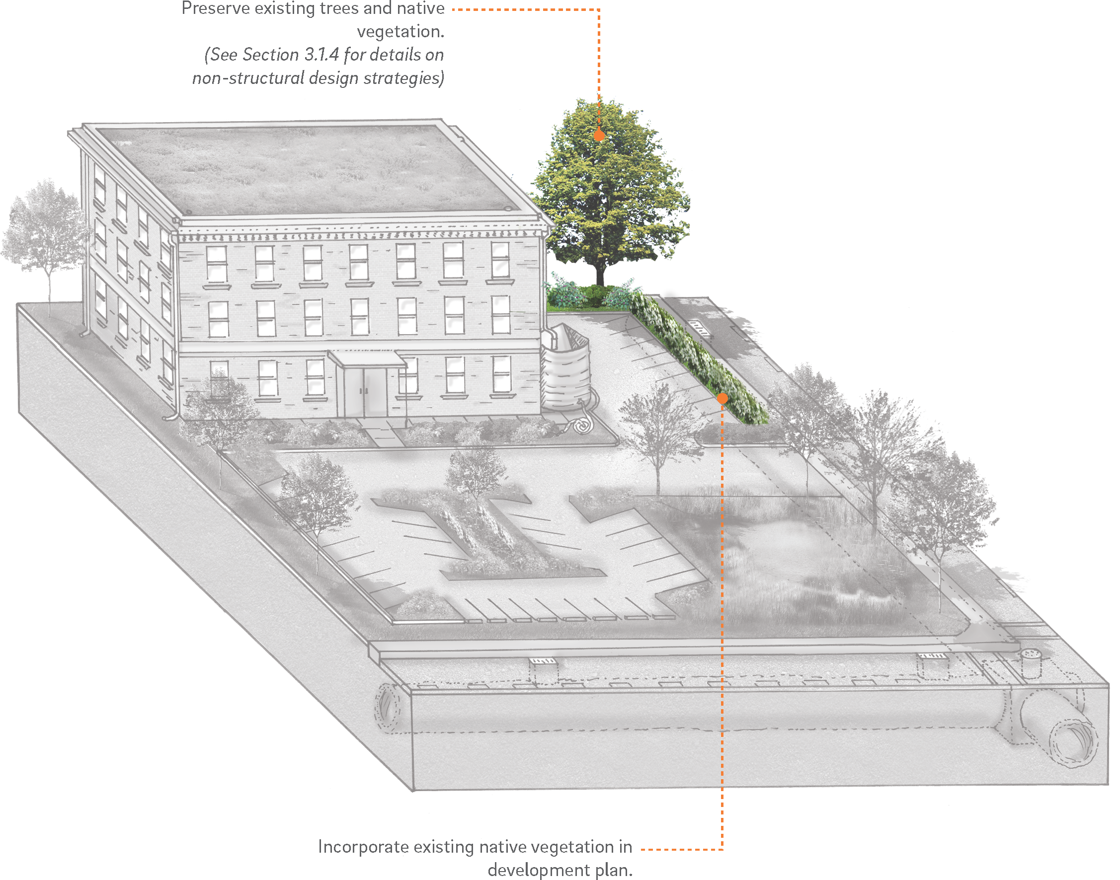
Preserve existing mature trees and native vegetation as illustrated in Figure 3.5‑1. Incorporate existing trees and native vegetation into the development plan.
Figure 3.5‑1: Commercial office building development example, Step 1
Step 2
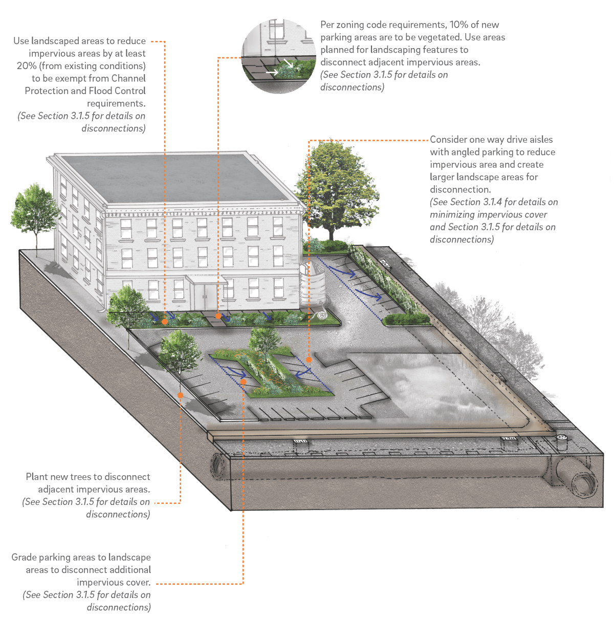
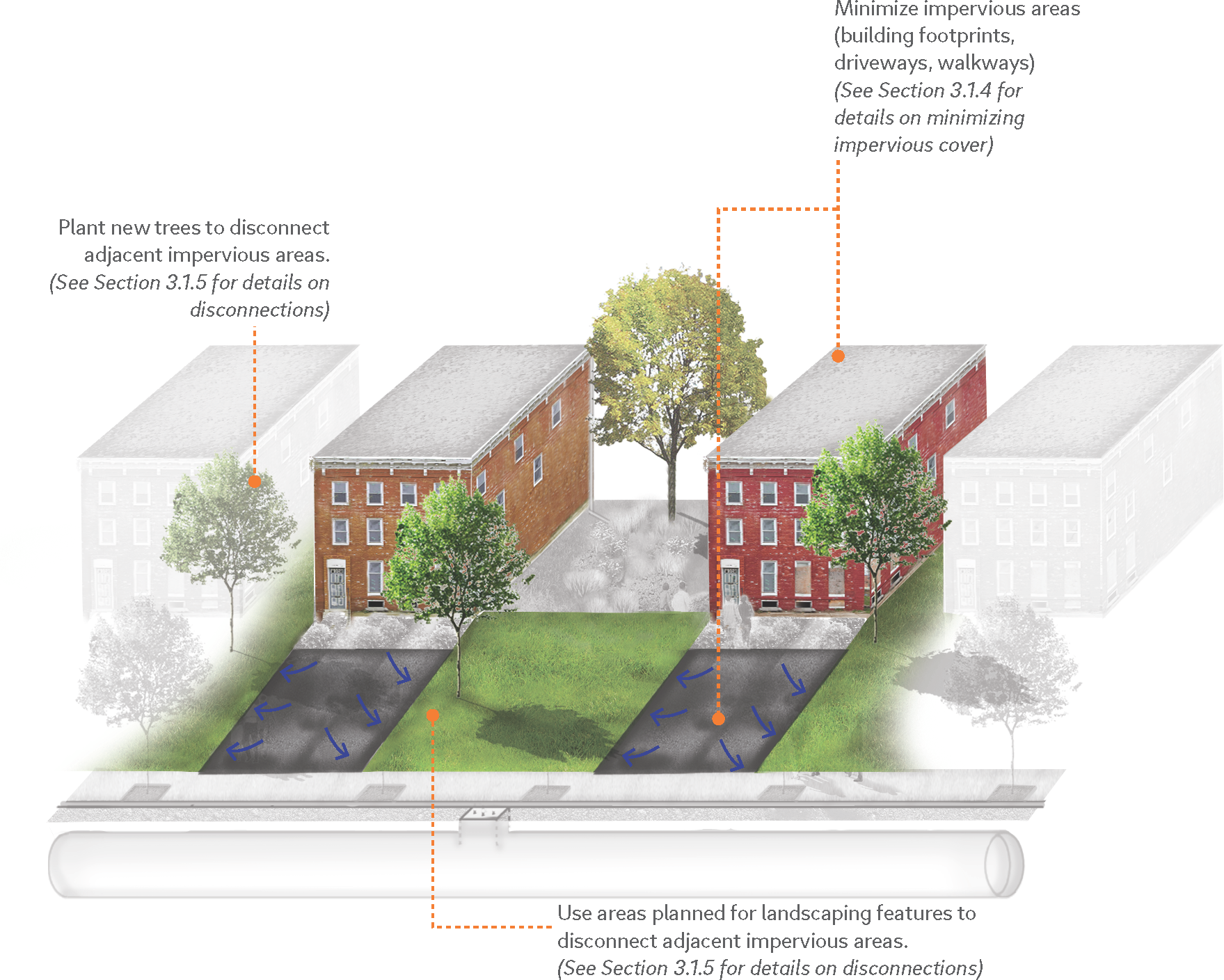
Minimize impervious areas and investigate opportunities to disconnect impervious areas as illustrated in Figure 3.5‑2.
Figure 3.5‑2: Commercial office building development example, Step 2
Step 3
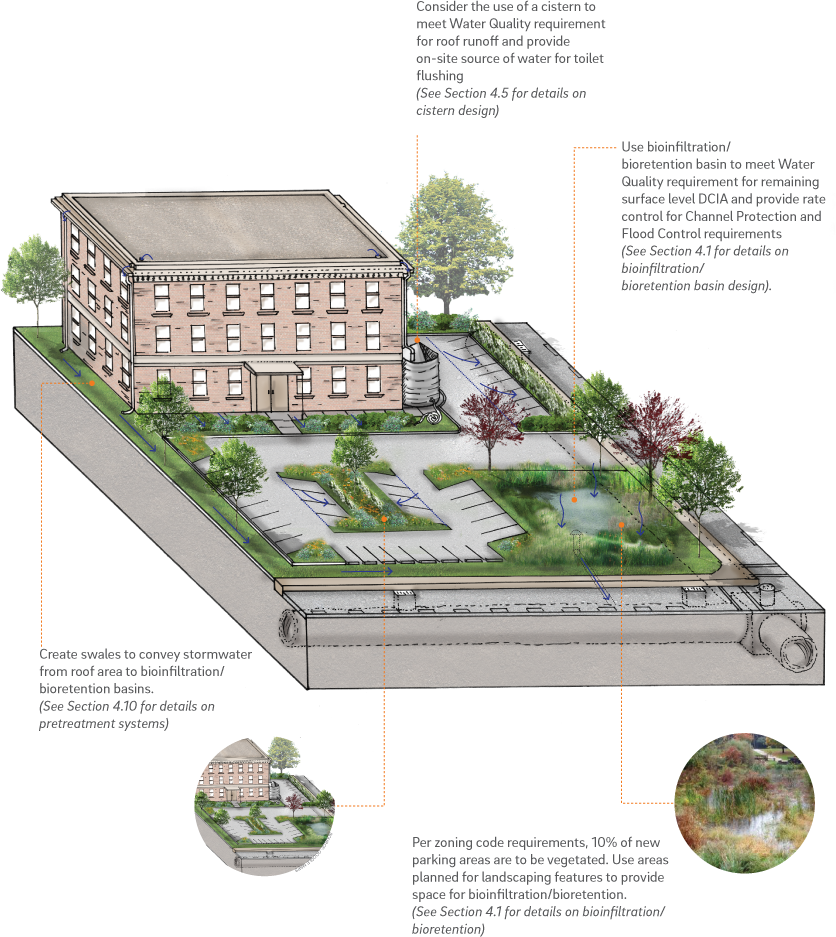
Use surface-vegetated stormwater management practices (SMPs) to manage runoff from a directly connected impervious area (DCIA) in order to meet the Philadelphia Water Department (PWD) Stormwater Regulations (Chapter 1), as illustrated in Figure 3.5‑3.
Figure 3.5‑3: Commercial office building development example, Step 3
3.5.2 Residential multi-family development
This example includes the same three-step process as described in the commercial office building development example and is illustrated in Figures 3.5‑4, 3.5‑5, and 3.5‑6.
Step 1
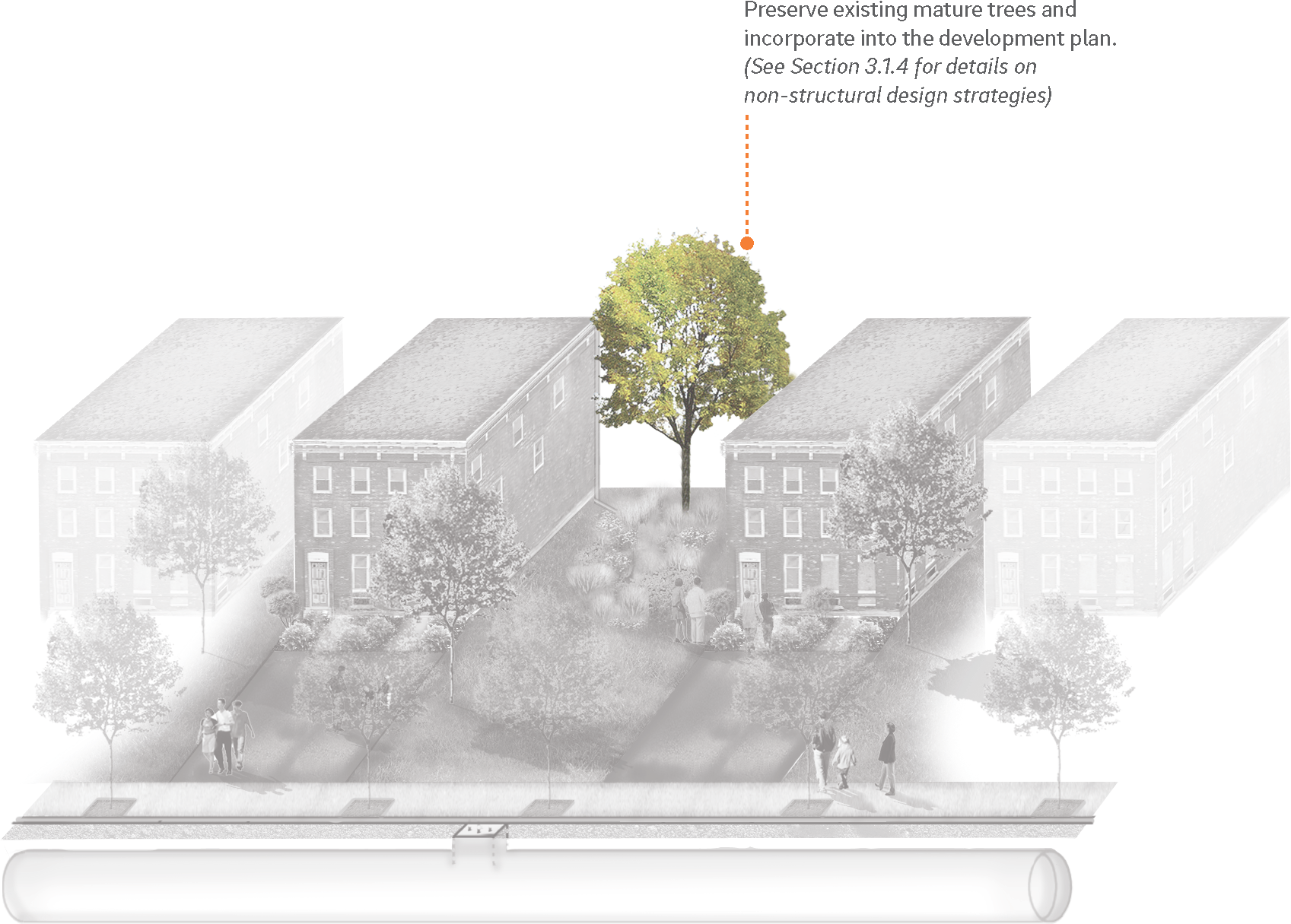
Preserve existing mature trees and native vegetation as illustrated in Figure 3.5‑4. Incorporate existing trees and native vegetation into the development plan.
Figure 3.5‑4: Residential multi-family development example, Step 1
Step 2
Minimize impervious areas and investigate opportunities to disconnect impervious areas as illustrated in Figure 3.5‑5.
Figure 3.5‑5: Residential multi-family development example, Step 2
Step 3
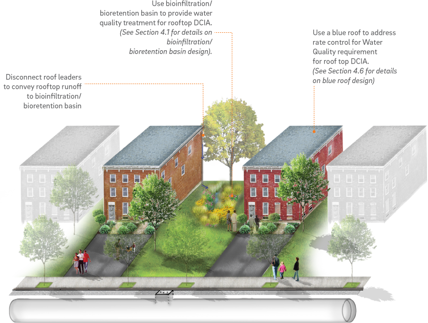
Use surface-vegetated SMPs to manage runoff from impervious areas in order to meet the Stormwater Regulations (Chapter 1), as illustrated in Figure 3.5‑6.
Figure 3.5‑6: Residential multi-family development example, Step 3
3.5.3 Full build-out
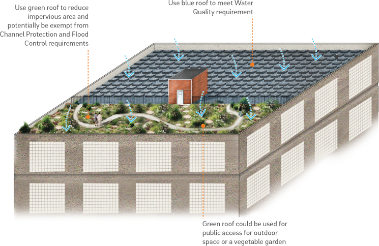
Non-structural options are limited for a full build-out scenario as the building footprint will cover the entire lot. For a full build-out project, the designer is encouraged to select green roof and cistern SMPs, as illustrated in Figure 3.5‑7, before considering subsurface practices, or to select a green roof/blue roof combination as illustrated in Figure 3.5‑8. If the project is a redevelopment project, by making a percentage of the roof area a green roof, the applicant may be able to demonstrate a 20% reduction in impervious area and be eligible for an exemption from Flood Control and Channel Protection requirements. A blue roof on the remainder of the same roof can be used to meet the Water Quality requirement peak release rate.
Figure 3.5‑7: Full build-out example, green roof
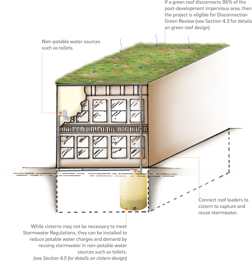
Figure 3.5‑8: Full build-out example, green roof / blue roof
3.5.4 Trails
A trail is defined as a relatively narrow pathway (not a road) used for pedestrian, bicycle, or small vehicle travel on public or private property. For the purposes of complying with the Stormwater Regulations, PWD will determine whether a proposed project may be considered a trail.
Figure 3.5‑9: Trail example
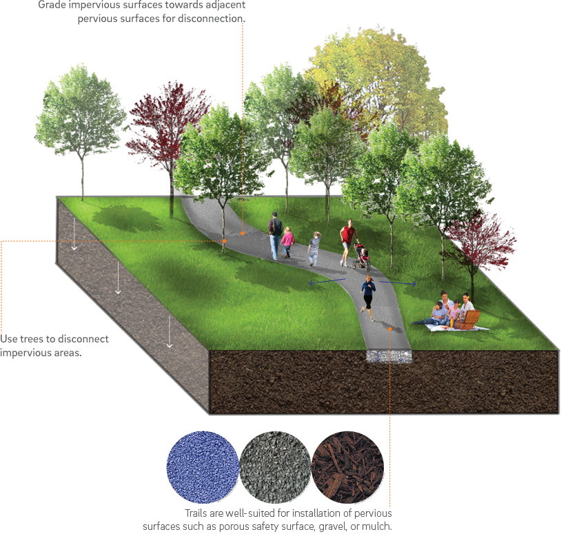
Trails may be paved or unpaved, as illustrated in Figure 3.5‑9. Pavements used to construct trails may be pervious or impervious. Examples of paved trails include off-road paths, greenway bike trails, and sidewalks. The trail designer is encouraged to first consider specifying pervious materials such as porous surfaces, gravel, or mulch for proposed trail projects. If pervious materials are not feasible or desired, the designer should consider a disconnected impervious cover (DIC) design approach, using porous surfaces, pavement disconnections, or tree disconnections. The designer is referred to Section 3.1.5 for more information on DIC options. As a last resort, the designer should consider using SMPs to manage stormwater runoff from proposed trail projects in order to meet the Stormwater Regulations.
By their nature, it may be difficult for trail projects to meet applicable Channel Protection and Flood Control requirements, so the use of DIC should be pursued before considering any SMP implementation.
3.5.5 Athletic fields
Athletic fields are typically made of pervious natural turf or porous artificial/synthetic turf but may or may not include run-on from adjacent DCIA. The replacement of existing athletic fields with natural turf often does not require an SMP for management of stormwater. For fields that include impervious surfaces, like new bleacher areas or team dugouts, the designer should first explore ways to disconnect these surfaces rather than proposing an SMP. Redevelopment projects that propose natural turf athletic fields are often eligible for an Expedited Post‑Construction Stormwater Management Plan (PCSMP) Review (Section 2.4). The designer should select natural turf options for field design when appropriate, as artificial turf fields will typically require structural and maintenance-intensive management strategies.
When artificial turf fields require maintenance, the turf surface or drainage components may need to be replaced. Replacement of the artificial turf surface, or repairs to the drainage system that do not expose the subbase, will not be considered earth disturbance. Modifications to the drainage system may affect the turf system’s ability to qualify as DIC.
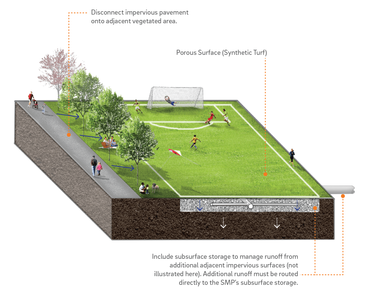
An example of a natural turf athletic field DIC is illustrated in Figure 3.5‑10. In this scenario, the designer should grade adjacent DCIA so that it can be disconnected to the vegetated areas. If this is not feasible, the designer should consider designing the athletic field to include a subsurface storage component to demonstrate compliance with the Stormwater Regulations, which is illustrated in Figure 3.5‑11.
Figure 3.5‑10: Natural turf athletic field example, DIC
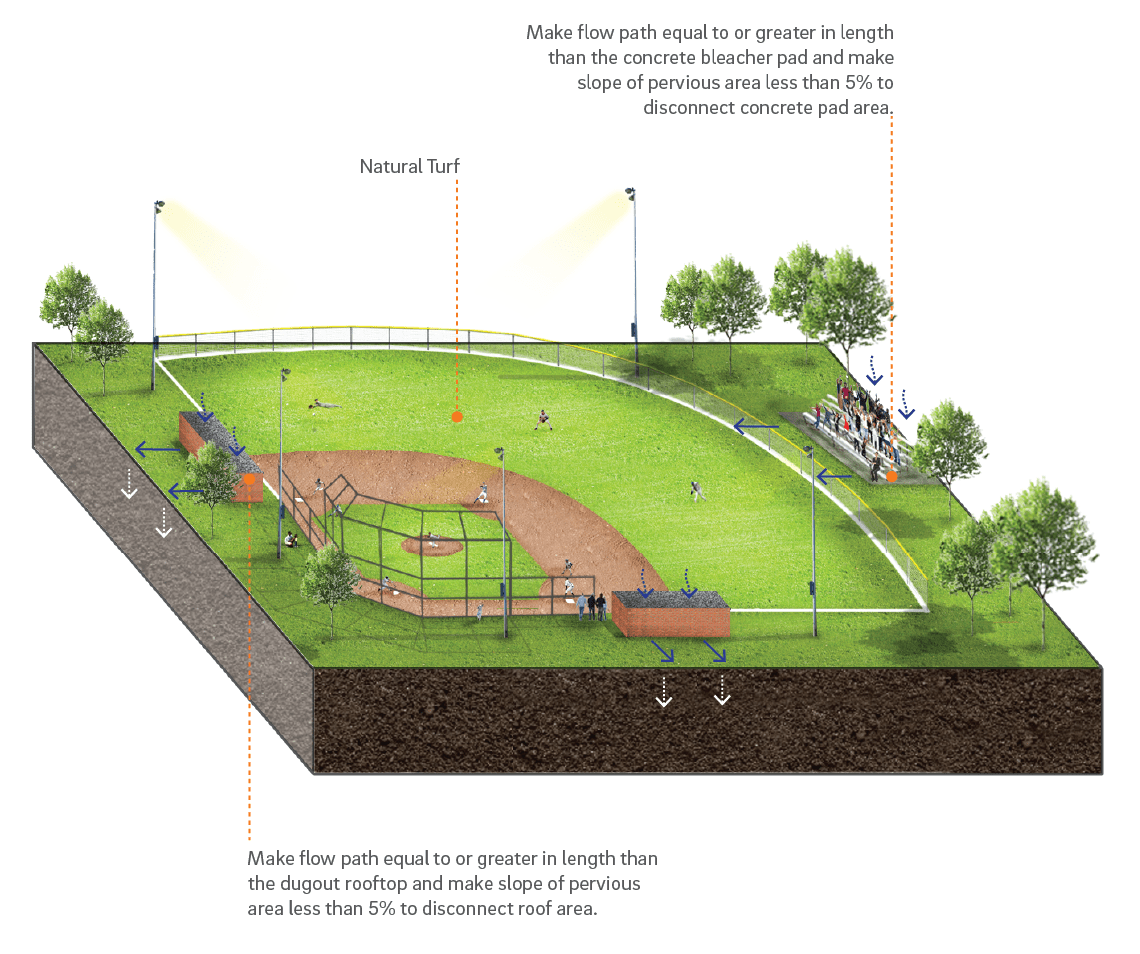
Figure 3.5‑11: Artificial turf athletic field example, subsurface SMP to manage DCIA
There are three main approaches for designing artificial, or synthetic, turf fields to meet the Stormwater Regulations: (1) designing the field to function as DIC; (2) designing the field, or a portion of the field, to function as an SMP; or (3) designing the field to convey stormwater to a separate SMP for treatment. The guidance below focuses on options (1) and (2), the two methods that are aimed at managing stormwater within the field itself and describe PWD’s design requirements that apply to each of these approaches. Although there are fundamental differences between the primary use, design, and construction of artificial turf fields and porous surface systems—like permeable pavers or reinforced turf—due to similarities in stormwater management function, PWD considers artificial turf fields to be classified as porous surfaces. As such, PWD’s requirements for artificial turf fields as stormwater management systems are similar to the requirements for porous surface systems.
- PWD will allow artificial turf fields to be considered DIC if design of the field is in accordance with the design requirements of porous surface DIC, as described in Section 4.2. If compaction of the subgrade is preferred for structural design purposes, infiltration testing must be performed during construction, after compaction of the subgrade, in accordance with Section 3.3. If infiltration is determined to not be feasible, the field area must be considered DCIA, treated as such when determining compliance with the Water Quality requirement, and modeled with a curve number of 98 in all required stormwater routing calculations. If an underdrain is proposed, the artificial turf field will only be considered DIC if the first 1.5 inches of runoff can be stored below the lowest invert of the underdrain.
- Any portion of an artificial turf field that receives stormwater runoff from impervious areas or is determined infeasible for infiltration must be considered DCIA rather than DIC. In this scenario, if any portion of the field system is designed to function as an SMP (as opposed to a conveyance system), that portion of the field must meet PWD’s requirements for subsurface basins. Infiltration testing is required in this case. After considering infiltration feasibility, the designer must adhere to the design requirements of either a subsurface infiltration system or subsurface detention system—detailed in Section 4.4 and Section 4.8, respectively.
- Stormwater runoff from the field may be directed to a separate SMP for management. The designer is referred to Chapter 4 for guidance and requirements for the design and implementation of a suite of acceptable SMPs.
3.5.6 Streets
When new streets are proposed as part of a development project, whether publicly or privately designated, the impervious area must be managed to meet the Water Quality requirement. To meet Water Quality, the runoff from the street must be directed to an on-site SMP. It is acceptable for the on-site SMP to manage runoff from both the street and the development site. On-site SMPs will be owned and maintained by the property owner (Chapter 6).
Private streets
New private streets can be managed in a similar manner to other private developments. Inlets, manholes, and conveyance piping will be owned and maintained by the property owner or their designee. In addition to the Water Quality requirement, the Channel Protection, Flood Control, and Public Health and Safety Release Rate requirements may also apply to the private street (Section 1.2.1). The designer should refer to Section 3.4.2 and Section 4.11 of this Manual for guidance on designing conveyance infrastructure.
Public streets
New public streets must be managed by the private SMP on the development site. As such, new public streets are typically designed with two different stormwater conveyance systems. A green system is used to manage the Water Quality storm from all the impervious surfaces, and a traditional grey sewer system serves as an overflow for larger storm events. A green stormwater system typically consists of Green Inlets, which are placed in the street to convey runoff to a junction box or manhole located at the property line that connects to the private SMP on the development site. A grey sewer system may be a single combined sewer or a separate stormwater-only sewer, depending on the connecting sewer network.
The on-site SMP should be sized to account for 1.5 inches of runoff over the proposed street drainage area, while any street conveyance systems should be sized to covey a 2.5 inches per hour precipitation intensity (the average peak 15-minute intensity from the 24‑hour rain gauge network in Philadelphia). This intensity translates to a 2.04‑inch 24‑hour storm event.
For conveyance of public street runoff, it is recommended that Green Inlets be located five feet upstream of an existing PWD inlet. For additional guidance on Green Inlet design, the designer is referred to Section 3.3.6, Inlets, of the PWD Green Stormwater Infrastructure Planning and Design Manual.
In most cases, the Green Inlet, inlet lateral, junction box, and the grey sewer system will be designed to PWD standards and located in a right-of-way., Upon completion, PWD will own and maintain these systems.
PWD’s Design Branch (Section 2.5) will be responsible for the review and approval of all infrastructure to be owned by PWD, facilitated concurrently with the PCSMP Review. PWD’s Construction Unit will inspect the proposed PWD infrastructure during construction to ensure installation meets PWD standards. The designer should contact PWD for the standard details and plan requirements for these conveyance features.