4.11.1 Inlet control introduction
Inlet controls are the structures or landscape features that manage the runoff flow into a stormwater management practice (SMP). Distribution piping, flow splitters, curbless design, curb openings, energy dissipaters, and inlets are all examples and elements of inlet controls. Inlet controls often serve an integral role in the pretreatment of stormwater entering an SMP by minimizing erosion potential or capturing sediment and gross solids. They restrict the volume and rate of flow introduced to an SMP while ensuring that flow is delivered to the SMP without causing erosion.
Design of inlet controls is not limited to the examples shown within this text. Successful stormwater management plans will combine appropriate materials and designs specific to each site.
Table 4.11‑1 below is a guide to the inlet controls covered in this section, showing whether they are typically used in conjunction with various SMP practices. Red indicates that an inlet control would typically be used with an SMP; yellow indicates that the inlet control may be used with the associated SMP in certain circumstances; and blue indicates that the inlet control would not typically be used with the associated SMP. An appropriate inlet control must be matched to the contributing drainage area and receiving SMP.
Table 4.11‑1: Inlet controls applicability guidance
| SMP | ||||
|---|---|---|---|---|
| Flow splitters | Curbless design / curb openings | Energy dissipaters | Inlets | |
| Bioinfiltration/ bioretention | Typical | Typical | Typical | Typical |
| Ponds and wet basins | Typical | Typical | Typical | Typical |
| Subsurface infiltration | Typical | Atypical | Atypical | Typical |
| Drainage wells | Typical | Atypical | Atypical | Typical |
| Cisterns | Typical | Atypical | Atypical | Occasional |
| Subsurface detention | Typical | Atypical | Atypical | Typical |
| Media filters | Occasional | Occasional | Occasional | Occasional |
| Porous surfaces | Atypical | Atypical | Atypical | Atypical |
| Green roofs | Atypical | Atypical | Atypical | Atypical |
| Blue‑green roofs | Atypical | Atypical | Atypical | Atypical |
| Blue roofs | Atypical | Atypical | Atypical | Atypical |
4.11.2 Flow splitters
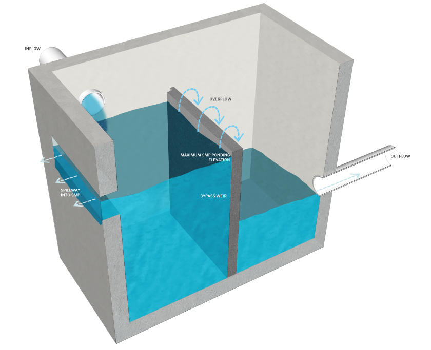
Flow splitting devices are used to direct a fraction of runoff into an SMP while bypassing excess flows from larger events around the SMP into a bypass pipe or channel. The bypass typically connects to another SMP or to a receiving drainage system, depending on the design and management requirements. This type of inlet control can also serve as the positive overflow for the SMP.
Flow splitters can be constructed by installing bypass weirs in stormwater control structures such as inlets and manholes. On a larger scale, they can be constructed using concrete baffles in manholes.
When can flow splitters be used?
Flow splitters are inlet controls that are typically applicable to bioinfiltration/bioretention basins, subsurface infiltration and detention SMPs, ponds and wet basins, and cisterns. Depending on the site layout and stormwater conveyance design, they may be applicable to media filters.
Flow splitters are used to divert required Water Quality Volume (WQv) to appropriate SMPs while allowing excess stormwater to pass to another SMP, storm sewer, or receiving water body. They may also be used to divert first flush stormwater to lower-maintenance surface SMPs while allowing excess flows to discharge to subsurface SMPs.
Key advantages of flow splitters
- Divide runoff volume and divert it to different destinations to alleviate downstream flooding during a storm or to prevent a SMP from exceeding its designed capacity
- Reduce the cost of building an SMP by reducing the storage capacity needed to provide positive overflow
- Enhance SMP longevity by reducing the volume of runoff treatment and the amount of erosion, slope, and vegetation damage
- Separate the first flush volume, which contains most of the runoff pollutants, allowing it to be sent to more intensive treatment SMPs or be treated for a longer period without being diluted by additional runoff, which can be diverted downstream or to another SMP
Key limitations of flow splitters
- Have the potential to cause flow reversal under certain circumstances (e.g., due to lack of backflow preventer or one-way valve) in which water will flow from an SMP back through the flow splitter
Key design considerations for flow splitters
- Flow splitters can be used as part of a connected system of SMPs to meet the Philadelphia Water Department (PWD) Stormwater Regulations (Stormwater Regulations). For example, a flow splitter can be used to divert portions of larger storm events from Water Quality requirement-meeting SMPs to SMPs better-suited to meet the Flood Control requirement.
- There are two basic considerations in the design of flow splitters: the elevation of the bypass weir and the capacity of the pipe to and from the SMP, which controls the maximum flow the SMP can receive and discharge.
Figure 4.11‑1: Flow splitter with typical features
Flow splitter design and material standards
- The elevation of the bypass weir dictates the maximum elevation of the water in the SMP. The bypass elevation must be set at minimum, at the design storage elevation in the SMP. Flow will then only start to bypass the SMP once it exceeds the design storage elevation of the SMP. The design storage elevation is the water surface elevation at which the SMP storage area contains the runoff volume from a design storm event (for example, the WQv or the ten‑year, 24‑hour storm).
- Positive overflow must be provided for large storm events, up to and including the 100‑year, 24‑hour storm, or, if the project is exempt from Flood Control, the ten‑year, 24‑hour storm. Overflow structures and pipes must be designed to convey at least the ten‑year, 24‑hour storm. The system should have enough capacity to transmit larger flows over the bypass weir without surcharging the structure.
- Flow splitters must be designed with appropriate materials, taking flow velocities and exposure to the elements into consideration. Flow splitters are typically constructed from reinforced concrete, galvanized steel, or brick and mortar.
- Flow splitters must be anchored to stormwater control structures using methods and materials appropriate to the structure’s environment, such as corrosion-resistant hardware or epoxy mortar.
4.11.3 Curbless design/curb openings
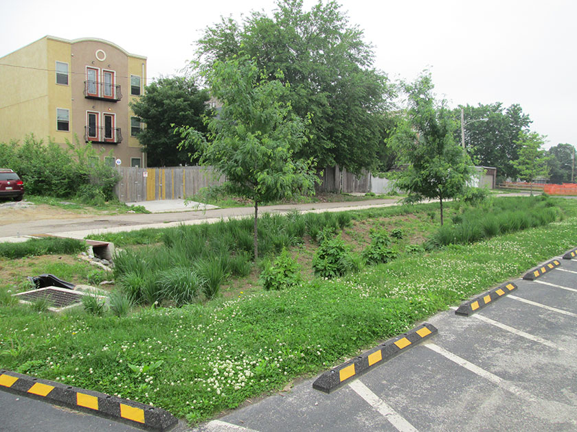
Curbless designs allow stormwater to flow directly from the impervious source to the SMP. This type of design discourages the concentration of flow and reduces the energy of stormwater entering an SMP. Curbless designs are often used with bioretention basin islands or roadside swales.
Curb openings provide an alternative inlet control when a curbless design or the use of inlet structures is not possible. Bioinfiltration/bioretention and landscaped islands in curbed parking lots or roadways often use curb openings as inlet controls.
When can curbless design/curb openings be used?
Curbless design/curb openings are inlet controls typically applicable to bioinfiltration/bioretention basins and ponds and wet basins. Depending on the site layout and stormwater conveyance design, they may be applicable to media filters.
Curbless design/curb openings can be implemented in a stormwater management design when standard inlet control and conveyance system structures are neither feasible, due to space or other constraints, nor desired.
Key advantages of curbless design/curb openings
- Can reduce SMP depths and associated excavation and materials costs when chosen in lieu of inlets
- Can be implemented as a strategy to reduce the concentration of stormwater flows into the SMP, thus reducing erosion potential
Key limitations of curbless design/curb openings
- Can result in limited control of bypass flows
- May not be appropriate for subsurface SMPs, large contributing drainage areas, contributing drainage areas with long flow paths over impervious areas, or along driveways or roadways where a sump condition is not feasible
Key design considerations for curbless design/curb openings
- A standard reference for designing traditional drainage systems is U.S. Army Corps of Engineers, Hydraulic Engineering Center Circular 22 (HEC‑22).
- Curb openings should be sized appropriately for sump or on-grade conditions. Further design guidance may be found in the Federal Highway Administration Urban Drainage Design Manual (FHWA-NHI-10-009), Section 4.4.4.2, Curb Opening Inlets.
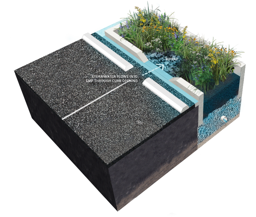
- Curbless designs should be designed with appropriate non-erosive linings, such as biodegradable erosion control fabric, turf reinforcement mat, stone, or riprap, on all pervious downslope areas to the full width of the curb opening/curbless design. Riprap aprons or riprap basins placed downstream of a flow path are also acceptable, but are considered energy dissipaters, which are discussed in Section 4.11.4.
- Trench drains can be used to convey flow from curb openings across sidewalks.
Figure 4.11‑2: Curb opening with typical features
Curbless design/curb opening design and material standards
- If flow is to be introduced through curb openings, the pavement edge must be slightly higher than the elevation of the vegetated areas within the SMP.
- Curbless design/curb openings must be designed to convey flow into an SMP without inducing erosive conditions. Integration of energy dissipaters is recommended where appropriate.
- Curb openings must be designed to reduce bypass of gutter flow past the curb opening. This is a common problem with many curb openings that are oriented perpendicular to flow.
- If curb openings are used to capture runoff, especially from driveways or roadways where the curb openings are not in a sump condition, verification that runoff from the one‑year, 24‑hour storm event will be captured by the curb opening must be provided.
- Roadway materials and thicknesses must be able to withstand the appropriate loads at the edge and prevent undercutting.
- Erosion control fabric must be designed in accordance with the channel design procedures in the latest edition of the Pennsylvania Department of Environmental Protection (PA DEP) Erosion and Sediment Pollution Control Program Manual, or per the manufacturer’s specifications.
- Curb openings are to be designed as gaps in otherwise continuous sections of concrete or granite curb conforming to the specifications of the City of Philadelphia Department of Streets, Standard Construction Items (1997).
- All subsurface portions of concrete or granite curb (i.e. below finished pavement grade) must be continuously installed within the extents of the curb opening.
- Pedestrian fall safety must be considered where the curb openings direct flow adjacent to or beneath sidewalks. The need for edge protection, such as railings or wheel stops, must be evaluated.
- Curb openings must be appropriately sized to convey the design discharge. Curb openings are typically 12 to 48 inches wide. Curb openings must be at least eight inches wide to prevent clogging and for ease of maintenance.
4.11.4 Energy dissipaters
Energy dissipaters are devices or practices designed to reduce the velocity, energy, and turbulence of flow. These structures can be employed when highly erosive velocities are encountered at the end of culverts or at the bottom of steep slopes where aesthetics are not a concern. Energy dissipaters include, but are not limited to, riprap aprons, riprap basins, and baffled outlets.
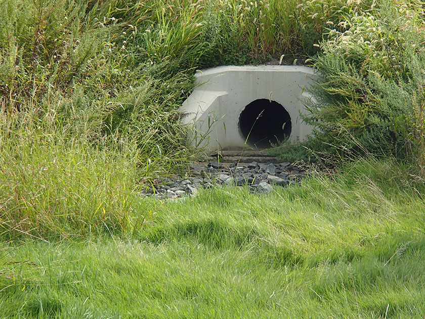
Riprap aprons are commonly used for energy dissipation due to their relatively low cost and ease of installation. A flat riprap apron can be used to prevent erosion at the transition from a pipe or box culvert outlet to a natural channel. Riprap aprons will provide adequate protection against erosive flows provided there is sufficient length and flare to dissipate energy by expanding the flow.
A riprap outlet basin is a pre-shaped scour hole lined with riprap that functions as an energy dissipater. Like a riprap apron, a riprap basin can be used to prevent erosion at the transition from a pipe or box culvert outlet to an earthen channel.
Baffled outlets are concrete or fiberglass boxes containing an alternating series of baffles and chambers. In addition to reducing flow velocity and energy, baffled outlets can effectively remove sediment, suspended particles, and associated pollutants from stormwater.
When can energy dissipaters be used?
Energy dissipaters are inlet controls typically applicable to bioinfiltration/bioretention basins and ponds and wet basins. Depending on the site layout and stormwater conveyance design, they may be applicable to media filters. They can be used downstream of other inlet controls that concentrate stormwater flow, as well as on steeper slopes, to reduce erosion potential.
Key advantages of energy dissipaters
- Reduce velocities of concentrated stormwater runoff
- Reduce erosion potential and allow for more efficient sediment removal efforts, reducing overall maintenance costs and improving SMP performance
- Prevent scour that may undermine the structure discharging concentrated stormwater runoff
- Prevent downslope erosion that may create gullies and scour holes
Key limitations of energy dissipaters
- May increase erosion if not properly designed and installed
- May be difficult to install on some steeply sloping areas and in highly constrained sites
Key design considerations for energy dissipaters
- Select an appropriate energy dissipater type based on site characteristics such as slope, available area, and aesthetics.
- A key design issue is the interface between the end of the energy dissipater and the adjacent downstream area, which is typically vegetated. Vegetation should be well established at this interface. Turf reinforcement mat may be used at this interface to provide additional structure for vegetation.
- Vegetation/plantings can be used to obscure views of energy dissipation structures if aesthetics is a concern.
Figure 4.11‑3: Riprap apron with typical features

Energy dissipater design and material standards
- Energy dissipaters must be used if flow is concentrated at the entrance to a surface SMP.
- Riprap must be designed and sized in accordance with the riprap apron design procedures in the latest edition of the PA DEP Erosion and Sediment Pollution Control Program Manual or U.S. Army Corps of Engineers, Hydraulic Engineering Center Circular 14 (HEC‑14). The designer is referred to HEC‑14 for the design of alternate types of energy dissipaters, such as drop structures and stilling basins.
- Riprap stone must be angular, graded stone aggregate meeting the specifications of PennDOT Publication 408, Section 703.2, Coarse Aggregate, Type A.
- For stream outfalls, the energy dissipation design tools HEC 11, HEC 14, and HEC 15 must be used for riprap, energy dissipaters, and flexible linings, respectively.
Energy dissipater maintenance guidance
All areas of the energy dissipater should be inspected after significant storm events for ponding. Corrective measures should be taken when excessive ponding occurs.
General recommended maintenance activities for energy dissipater are summarized in Table 4.11‑2.
Table 4.11‑2: Energy dissipater maintenance guidelines
| Ongoing maintenance activity | Frequency |
|---|---|
| Inspect energy dissipaters after storms for displaced stones, slumping, and erosion at edges, particularly downstream or downslope. Repair or replace damaged riprap. | Monthly/concurrent with storm events |
| Inspect dissipater area for sediment and other debris accumulations. Remove sediment and other debris accumulations from dissipater area. | Quarterly |
| Inspect for woody vegetation build-up. Remove woody vegetation from the riprap. | Quarterly |
| Inspect stream for obstructions, such as debris, fallen trees, and sediment bars, if riprap is located on a channel bank. Remove obstructions. | Quarterly |
| Inspect any underlying fabric for damage. Repair or replace damaged fabric. | Quarterly |
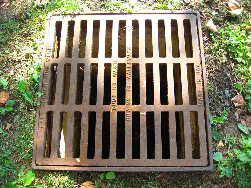
4.11.5 Inlets
Inlets, or catch basins, are structures within traditional stormwater collection systems where water is collected before it enters a pipe network. These structures can be designed with inlet pretreatment devices.
Inlet pretreatment devices are structural screens, hoods, traps, racks, bags, or suspended catch basin inserts inserted into the inlet to filter debris before it can enter the SMP’s distribution piping system. They offer a range of screening capacity. Hoods and trash racks, for example, offer a coarse level of protection, typically screening only large debris and/or floatables. Filter screens or bags, available in a variety of proprietary designs, may filter large sediment particles, in addition to floatables and large debris. Stormwater Retrofit projects planning to utilize existing inlets without hoods and sites that generate pollutants such as loading docks, material storage facilities, junk yards, and waste collection and disposal sites require permanent filter bag inserts as inlet pretreatment devices.
The designer is referred to Section 4.10 for more information on Pretreatment.
When can inlets be used?
Inlets are typically applicable to bioinfiltration/bioretention basins, subsurface infiltration and detention SMPs, and ponds and wet basins. Depending on the site layout and stormwater conveyance design, they may be applicable to cisterns and media filters.
Inlets may be used as an inflow device for any SMP where curb and gutter design is desired or required.
Key advantages of inlets
- Can provide a stable, relatively low-maintenance point for stormwater to enter an SMP
- Allow for pretreatment of stormwater runoff upstream of SMPs
Key limitations of inlets
- Can often result in deeper SMPs than those with curbless design/curb openings due to outlet pipe inverts
- May store and release re-suspended captured sediment during subsequent flows unless frequently maintained
- Can become a source of pollutants through resuspension unless frequently maintained
- Cannot effectively remove soluble pollutants or fine particles
Key design considerations for inlets
- A standard reference for designing traditional drainage systems is U.S. Army Corps of Engineers, Hydraulic Engineering Center Circular 22 (HEC‑22).
- Clogging of an SMP’s distribution piping system can be reduced by equipping upstream inlets with pretreatment devices such as structural screens, hoods, traps, racks, bags, or suspended catch basin inserts.
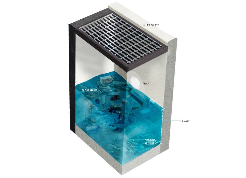
Figure 4.11‑4: Inlet with typical features
Inlet design and material standards
- Inlets must not be connected in series. Similarly, roof drainage systems must not be directly connected to inlets.
- All inlets must include a sump and trap or sump and hood for pretreatment of stormwater runoff. The sump depth must be at least 15 inches below the bottom of the trap or at least 12 inches below the bottom of the hood.
- If non-standard inlets are used to capture runoff, especially from driveways or roadways where the inlets are not in a sump condition, verification that runoff from the one‑year storm event will be captured by the inlet must be provided.
- Inlet spacing must be designed to prevent water from overtopping the curb and gutter or drainage ditch.
- Inlets must be sized based on the size of the contributing drainage area, the amount of sediment expected from the discharging waters, the size and frequency of runoff events, and the amount of maintenance expected, recognizing that an undersized system will require more frequent maintenance. For large inlet drainage areas, area drains and yard drains 18 inches in diameter or smaller, or smaller than 2’ x 2’, should be upsized to at least 2’ x 2’ inlets.
- All area drains and yard drains 18 inches in diameter or smaller, or smaller than 2’ x 2’, must include a permanent pretreatment device, such as a filter bag insert, for pretreatment of stormwater runoff.
- The designer is referred to the City of Philadelphia Standard Details and Standard Specifications for Sewers booklet and the Philadelphia Plumbing Code, Section P-1001.7 for more design and material guidance.
- All inlets on sites that generate pollutants, such as loading docks, material storage facilities, junk yards, and waste collection and disposal sites, must include a permanent filter bag insert.
Inlet maintenance guidance
Table 4.11‑3 below is a schedule of recommended inspection and maintenance activities for inlets.
Table 4.11‑3: Inlet maintenance guidelines
| Ongoing activity | Frequency |
|---|---|
| Inspect inlets after several storms to ensure that they are functioning properly and that there are no erosion problems developing. | As needed |
| Identify and control source of sediment contamination when in situ soil is exposed or erosion channels are present. | As needed |
| Replace filter bags for pretreatment devices. Ensure filter bag is installed properly. | Quarterly |
| Inspect all pipe connections and parge ensuring a watertight seal. | Quarterly |
| Inspect for sediment and debris build-up. Remove sediment build | Semiannually |
| Clean out leaves, trash, and debris. | Semiannually |
| Maintain records of all inspections and maintenance activity. | Ongoing |