Download summaries of this SMP and its maintenance guidance, with quick reference information for clients and developers:
- Bioinfiltration/Bioretention SMP One‑Sheet
- Bioinfiltration/Bioretention Maintenance Guidance One‑Sheet
4.1.1 Bioinfiltration/bioretention introduction
Bioinfiltration and bioretention stormwater management practices (SMPs), often referred to as rain gardens, are vegetated depressions or basins that use surface storage, vegetation, planting soil, outlet controls, and other components to treat, detain, and retain stormwater runoff. Bioinfiltration and bioretention SMPs represent the highest level of preference in the Philadelphia Water Department’s (PWD’s) SMP Hierarchy by providing high-performance and cost-effective stormwater management, green space, and triple bottom line benefits. Both types of SMPs reduce stormwater volume and pollution by filtering runoff through a vegetated soil medium that promotes evapotranspiration. Bioinfiltration SMPs remove stormwater via infiltration into the surrounding soils while bioretention SMPs attenuate runoff with flow-regulating underdrains.
Bioinfiltration/bioretention SMPs can be found in a variety of configurations, from relatively large and open vegetated basins to small-scale SMPs contained within flow-through planter boxes. These SMPs can be combined with other SMPs in series to meet the PWD Stormwater Regulations (Stormwater Regulations). The designer is referred to Section 3.2.3 for information on using SMPs in series.
Because bioinfiltration and bioretention SMPs are ranked highest in the SMP Hierarchy (Section 3.2.2), special design guidance is provided in this section to promote their use. This design guidance provides flexibility for designers to either dynamically model bioinfiltration or to follow a prescribed design based on the drainage area without performing infiltration testing. The dynamic routing allows designers to account for the volume of water infiltrated into the ground in real time, which allows the bioinfiltration SMP to have less storage and be shallower. The prescribed design makes use of the minimum requirements set forth in the Standard Detail (Figure 4.1‑4) and the Bioinfiltration/bioretention basin sizing table (Table 4.1‑4), ensuring that bioinfiltration/bioretention SMPs can be fully designed and approved for Water Quality compliance without knowledge of infiltration feasibility. Therefore, postponement of infiltration testing until construction of the evelopment project is permitted; the results of the infiltration testing will dictate whether an underdrain cap should be equipped with an orifice. Additionally, development projects incorporating only disconnected impervious cover and bioinfiltration/bioretention SMPs may be eligible for a Surface Green Review. The designer is referred to Section 2.4 for details on the Expedited Post‑Construction Stormwater Management Plan (PCSMP) Review submission process.
When can bioinfiltration/bioretention be used?
Bioinfiltration SMPs must have underlying soils that, when tested pursuant to the infiltration testing procedure described in Section 3.3, are determined to be infiltration-feasible. Where infiltration is not feasible, bioretention SMPs can be used by converting capped underdrains to flow-regulating underdrains to comply with the Water Quality requirement. The designer is referred to Section 3.3 for guidance on infiltration testing.
Bioinfiltration/bioretention SMPs can be used to manage stormwater on small and large sites. For example, bioinfiltration/bioretention may be integrated into smaller sites using flow-through planter boxes or integrated into larger sites by using multiple bioinfiltration/bioretention basins throughout the project area.
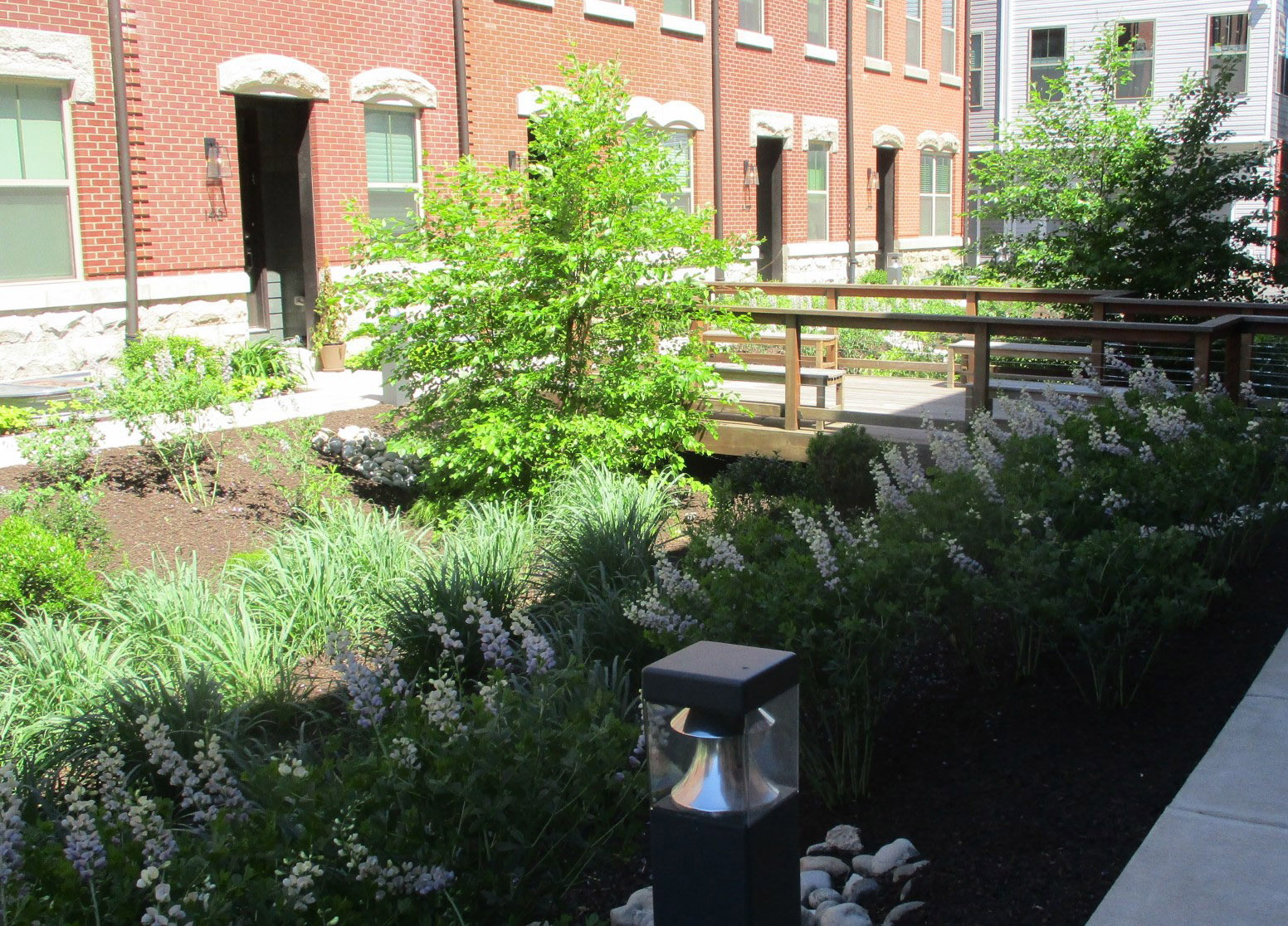
Bioinfiltration/bioretention SMPs are also suitable for many types and sizes of development, from multi-family residential to high-density commercial projects, and are viewed as an integral part of a development’s landscape design during site layout, doubling as both a landscape amenity and stormwater management feature.
At commercial, industrial, and institutional sites, areas for stormwater management and green space are often limited. At these sites, bioinfiltration/bioretention SMPs serve multiple purposes of stormwater management and landscaping by managing runoff from impervious site areas such as parking lots, sidewalks, and rooftops. Bioinfiltration SMPs can also be dynamically sized to save space or reduce the depth of the SMP.
A parking lot is an ideal location for bioinfiltration/bioretention SMPs. These SMPs can be incorporated as an island, median, or along the perimeter of the parking area. Bioinfiltration/bioretention SMPs can enhance the aesthetics of a parking lot while managing stormwater from the site.
Key advantages of bioinfiltration/bioretention
- Flexible layout and easy to incorporate in landscaped areas
- Very effective at removing pollutants and reducing runoff volumes
- Generally, one of the more cost-effective stormwater management options
- Relatively low maintenance activities costs
- Can contribute to better air quality and help reduce urban heat island impacts
- Can improve property values and site aesthetics through attractive landscaping
- Can provide educational benefits, especially when used at public and/or highly visible sites such as schools, recreation centers, libraries, etc.
- Eligible for inclusion in an Expedited PCSMP Review project
- Above benefits may be maximized with the inclusion of trees
- Bioinfiltration SMPs are eligible for dynamic sizing
Key limitations of bioinfiltration/bioretention
- May need to be combined with other SMPs to meet the Flood Control requirement
- May have limited opportunities for implementation based on the amount of open space available at the site
Key design considerations for bioinfiltration/bioretention
- Bioinfiltration/bioretention SMPs should be considered as an alternative before designing subsurface infiltration and detention SMPs. Bioinfiltration/bioretention SMPs are preferred for several reasons, including installation and maintenance cost, ease of maintenance, habitat creation, nutrient cycling, and aesthetics.
- Bioinfiltration SMPs can be dynamically designed, which may save space or reduce the depth of the SMP. These SMPs must statically store one inch of runoff and be shown, via dynamic routing, to manage 1.5 inches of runoff throughout the design storm, without overflow.
- The pretreatment approach should be matched to site characteristics. Bioinfiltration/bioretention SMPs rely on flow through soil media to provide Water Quality treatment. Media layers can become clogged, particularly when runoff has high quantities of sediment. To avoid this, SMPs managing runoff from surfaces that generate high sediment loads should have adequate pretreatment to remove dirt and grit before they reach the bioinfiltration/bioretention SMP.
- The SMPs should be viewed as landscape features. Viewing bioinfiltration/bioretention SMPs as an integral part of a site’s landscape design can help identify key implementation locations. Bioinfiltration/bioretention SMPs can double as landscape features on many sites, providing landscape amenities and stormwater management in the same location.
- Non-basin designs can be used for small spaces. Integrating bioinfiltration/bioretention into flow-through planter boxes or tree pits can be an effective way of incorporating bioinfiltration/bioretention functions into spatially constrained sites.
- Safety issues relating to ponding depth should be carefully considered, particularly for sites where small children will be proximate to the installation.
- Balancing cut and fill can reduce costs. A berm placed on the downslope side of a mild slope can help retain stormwater and increase capacity without additional excavation.
- For constrained sites, using additional subsurface stone to meet storage volume needs should be considered. Bioinfiltration SMPs can also be dynamically designed to save space.
- Areas of soil contamination should be avoided; however, in some cases, an impervious liner may be appropriate for separating bioinfiltration/bioretention SMPs from these underlying conditions.
- Whenever possible, the designer should preserve existing trees and develop tree protection plans. A plan should be developed for the removal of invasive species both in and around the project area.
- A diverse planting palette should be used. A diverse community of native plants is recommended to minimize susceptibility to insect and disease infestation and reduce long-term maintenance requirements. A mixture of herbaceous plants, grasses, shrubs, and trees is generally recommended to create a microclimate that can ameliorate urban stresses, discourage weed growth, and reduce maintenance needs.
- Smart plant selection for the site should be a focus. It is critical that plant materials are appropriate for soil, hydrologic, light, and other site conditions. The designer is referred to the list of native and recommended non-invasive species in Appendix I. Ponding depth, drainage time, sunlight, salt tolerance, and other conditions should be taken into consideration when selecting plants. Turf grass is generally not recommended but may be acceptable provided the designer can demonstrate that it meets all applicable requirements. The designer is referred to Section 4.13, Landscaping, for additional guidance.
- The designer should choose low maintenance plants that minimize the need for mowing, pruning, and irrigation.
- The characteristics of the soil for the bioinfiltration/bioretention SMP are perhaps as important as the facility location, size, and treatment volume. The soil must be permeable enough to allow runoff to filter through the media, while having characteristics suitable to promote and sustain a robust vegetative cover crop. In addition, much of the nutrient pollutant uptake (nitrogen and phosphorus) is accomplished through adsorption and microbial activity within the soil profile. Therefore, the soils must balance soil chemistry and physical properties to support biotic communities above and below ground.
- Flow-through planter box planting requires that plants be supplied with nutrients that they would otherwise receive from being part of an ecosystem. Since they are cut off from these processes, they must be cared for accordingly.
- Generally, six‑inch to twelve‑inch centers with triangular spacings for plugs are recommended.
- Mulch for a bioinfiltration/bioretention SMP should have a minimum depth of two inches.
- For any bioinfiltration/bioretention SMP that discharges onto an adjacent property, a drainage easement may be required and is recommended.
4.1.2 Bioinfiltration/bioretention components
Figure 4.1‑1: Bioinfiltration/bioretention basin with typical features
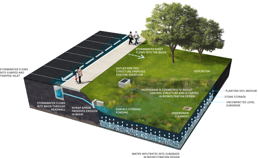
Pretreatment component
Pretreatment systems capture trash, sediment, and/or other pollutants from stormwater runoff before delivery to the storage or infiltration area. Pretreatment needs will vary significantly depending on the contributing drainage area composition and use. Pretreatment can include structures such as sumped and trapped inlets, sediment/grit chambers or separators, media filters, inlet inserts, or other appropriate prefabricated or proprietary designs to remove sediment, floatables, and/or hydrocarbons from stormwater runoff prior to being conveyed to a bioinfiltration/bioretention SMP. While inlet hoods are preferred, permanent filter bags may be accepted for Stormwater Retrofit projects where existing inlets do not have hoods and inlet reconstruction is not feasible. In addition to sumped and trapped inlets, permanent filter bag inserts are required for sites that generate pollutants such as loading docks, material storage facilities, junk yards, and waste collection and disposal sites. Permanent filter bags will require frequent cleanings.
Pretreatment can also consist of filter strips, forebays, and swales. The designer is referred to Section 4.10, Pretreatment, for more information.
Inlet control component
Inlet control systems convey and control the flow of stormwater from the contributing catchment area to a bioinfiltration/bioretention SMP. Inlet control needs will vary depending on the design of stormwater conveyance systems and the site layout. The designer is referred to Section 3.4.2 for guidance on stormwater conveyance system design.
Inlet controls may include flow splitters, curbless design/curb openings, energy dissipaters, and inlets. The designer is referred to Section 4.11, Inlet Controls, for more information.
Storage area component
Storage areas within bioinfiltration/bioretention SMPs temporarily hold stormwater runoff until it can either infiltrate into native soils, evaporate, be used by plants through transpiration, or be released downstream at a controlled rate, depending on the SMP design. Bioinfiltration/bioretention SMPs can include both surface and subsurface storage areas.
Surface storage is typically provided by excavating an area to create a depression. Surface storage for bioinfiltration/bioretention SMPs can also be created using curbing or concrete structures such as flow-through planter boxes. It provides temporary storage of stormwater runoff before infiltration, evaporation, and uptake can occur within the bioinfiltration/bioretention SMP. Ponding time provides Water Quality benefits by allowing larger debris and sediment to settle out of the water. Maximum surface ponding depth requirements are provided in order to reduce hydraulic loading on underlying soils, ensure adequate drain down time, and prevent standing water.
Figure 4.1‑2: Flow-through planter box with typical features
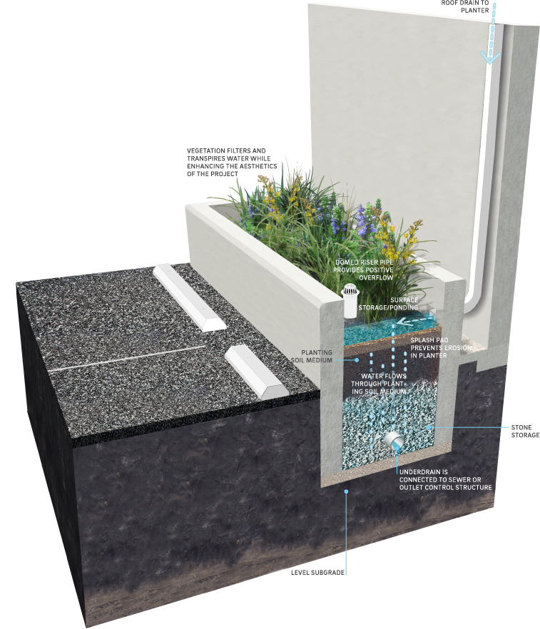
Beneath surface storage areas, prepared planting soil medium provides subsurface storage capacity. This storage capacity is a function of the soil depth, surface area, and void space. The planting soil medium serves as the primary Water Quality treatment mechanism of a bioinfiltration/bioretention SMP, filtering runoff before it reaches the native soil (for bioinfiltration SMPs) or before it reaches the downstream discharge point (for bioretention SMPs).
The characteristics of the soil for the bioinfiltration/bioretention SMP are perhaps as important as the facility location, size, and treatment volume. The soil must be permeable enough to allow runoff to filter through the media, while having characteristics suitable to promote and sustain a robust vegetative cover crop. In addition, much of the nutrient pollutant uptake (nitrogen and phosphorus) is accomplished through adsorption and microbial activity within the soil profile. Therefore, the soils must balance soil chemistry and physical properties to support biotic communities above and below ground.
Many bioinfiltration/bioretention SMPs include an additional subsurface storage component, typically constructed of a stone-filled, level-bottomed bed or trench. The void spaces between the stones store stormwater until it can infiltrate into the surrounding soils or be released downstream.
A mulch or organic layer, atop the planting soil medium, provides a medium for biological growth, decomposition of organic material, and adsorption of pollutants such as heavy metals. The mulch layer can also absorb some water during storms and help the planting soil retain water for plant growth during dry periods.
Vegetation component
Plant material in a bioinfiltration/bioretention SMP removes nutrients and stormwater pollutants through vegetative uptake and microbial community support, removes water through evapotranspiration, creates pathways for infiltration (in bioinfiltration SMPs) through root development and plant growth, improves aesthetics, provides habitat, and helps to stabilize soil.
The proper selection and installation of plant materials is critical to a successful bioinfiltration/bioretention SMP. There are essentially six zones within a bioinfiltration/bioretention SMP (Figure 4.1‑3). The lowest elevation supports plant species adapted to standing and fluctuating water levels. The middle elevation supports a slightly drier group of plants, but still tolerates fluctuating water levels. The outer edge is the highest elevation and generally supports plants adapted to drier conditions. However, plants in all zones should be drought tolerant.
Figure 4.1‑3: Hydrologic zones of a bioinfiltration/bioretention basin
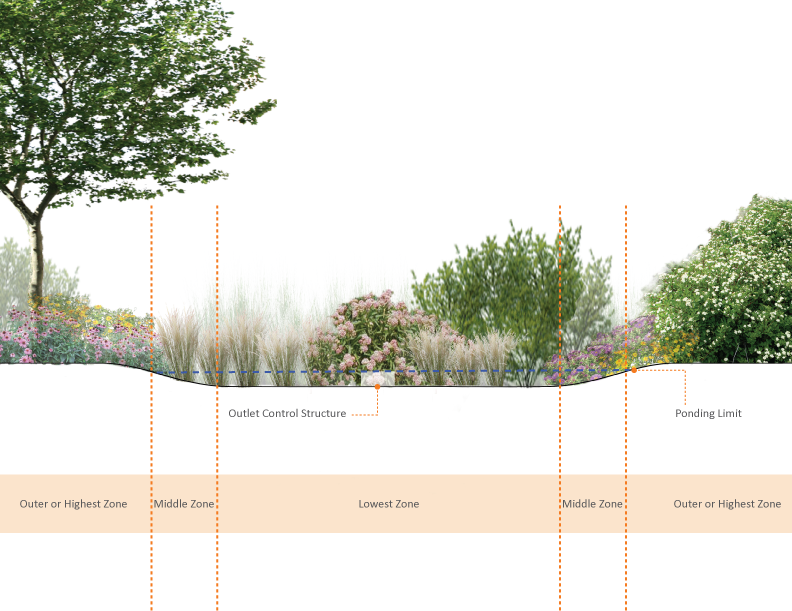
The lowest zone (hydrologic zones 2–4) contains plant species adapted to standing and fluctuating water levels and frequent inundation. Frequently used native plants include the following species. The designer is referred to Table I‑1 in Appendix I for a complete listing.
Table 4.1‑1: Frequently used native plants for hydrologic zones 2–4
| Frequently used native plants for hydrologic zones 2–4 | |
|---|---|
| asters (Aster spp.) | winterberry (Ilex verticillata) |
| goldenrods (Solidago spp.) | arrowwood (Viburnum dentatum) |
| bergamot (Monarda fistulosa) | sweet pepperbush (Clethra alnifolia) |
| blue-flag iris (Iris versicolor) | bayberry (Myrica pensylvanica) |
| sedges (Carex spp.) | buttonbush (Cephalanthus occidentalis) |
| ironweed (Vernonia noveboracensis) | swamp azalea (Rhododendron viscosum) |
| blue vervain (Verbena hastata) | elderberry (Sambucus canadensis) |
| joe-pye weed (Eupatorium spp.) | red maple (Acer rubrum) |
| swamp milkweed (Asclepias incarnata) | river birch (Betula nigra) |
| switchgrass (Panicum virgatum) | sweetgum (Liquidambar styraciflua) |
| shrub dogwoods (Cornus spp.) | northern white cedar (Juniperus virginiana) |
The middle zone (hydrologic zones 4–5) is slightly drier than the lowest zone, but plants should still tolerate fluctuating water levels. Frequently used native plants include the following species. The designer is referred to Table I‑1 in Appendix I for a complete listing.
Table 4.1‑2: Frequently used native plants for hydrologic zones 4–5
| Frequently used native plants for hydrologic zones 4–5 | |
|---|---|
| black snakeroot (Cimicifuga racemosa) | spicebush (Lindera benzoin) |
| switchgrass (Panicum virgatum) | hackberry (Celtis occidentalis) |
| spotted joe-pye weed (Eupatorium maculatum) | willow oak (Quercus phellos) |
| cutleaf coneflower (Rudabeckia lacinata) | winterberry (Ilex verticillata) |
| frosted hawthorn (Crataegus pruinosa) | slippery elm (Ulmus rubra) |
| marginal wood fern (Dryopteris marginalis) | viburnums (Viburnum spp.) |
| ironwood (Carpinus caroliniana) | witch-hazel (Hamamelis virginiana) |
| serviceberry (Amelanchier canadensis) | steeplebush (Spiraea tomentosa) |
| obedient plant (Physostegia virginiana) | blueberry (Vaccinium spp.) |
The outer zone (hydrologic zones 5–6) generally supports plants adapted to drier conditions. Frequently used native plants include the following species. The designer is referred to Table I‑1 in Appendix I for a complete listing.
Table 4.1‑3: Frequently used native plants for hydrologic zones 5–6
| Frequently used native plants for hydrologic zones 5–6 | |
|---|---|
| basswood (Tilia americana) | sweet-fern (Comptonia peregrina) |
| white oak (Quercus alba) | eastern red cedar (Juniperus virginiana) |
| scarlet oak (Quercus coccinea) | smooth serviceberry (Amelanchier laevis) |
| black oak (Quercus velutina) | American holly (Ilex opaca) |
| american beech (Fagus grandifolia) | sassafras (Sassafras albidum) |
| black chokeberry (Aronia melanocarpa) | white pine (Pinus strobus) |
Outlet control component
Outlet controls within a bioinfiltration/bioretention SMP can provide a range of functions, including the following:
- Controlling how much water is stored for infiltration (for bioinfiltration SMPs);
- Meeting drain down time requirements;
- Controlling the rate of discharge from the SMP and limiting water surface elevations during various storm events; and
- Bypassing of flows from large storm events.
Outlet controls may include orifices, weirs, risers, or underdrains. The designer is referred to Section 4.12, Outlet Controls, for more information.
Inspection and maintenance access component
Safe and easy inspection and maintenance access to all major components within a bioinfiltration/bioretention SMP is critical to ensuring long-term performance. Cleanouts provide a means to maintain any installed underdrains. Mildly sloping, stabilized, and graded areas also provide access to surface storage areas for heavy equipment, which may be needed for sediment removal.
4.1.3 Bioinfiltration/bioretention design standards
The designer is encouraged to design bioinfiltration/bioretention SMPs meeting the minimum requirements set forth in the Bioinfiltration/bioretention basin Standard Detail (Figure 4.1‑4) in conjunction with the Bioinfiltration/bioretention basin sizing table (Table 4.1‑4). Basins sized as such provide Water Quality compliance in all sewersheds and regardless of infiltration feasibility, with only minor modification necessary to the capped underdrain during construction. As a result, bioinfiltration/bioretention SMPs can be designed without knowledge of infiltration feasibility.
If infiltration is deemed feasible, the designer may elect to dynamically design the bioinfiltration SMP. The dynamically designed SMP must still meet all applicable requirements, but it may be designed to statically store one inch of runoff, rather than the full 1.5‑inch Water Quality Volume (WQv). If this strategy is chosen, the designer must show, via dynamic routing, that the full 1.5‑inch WQv is managed throughout the design storm, without overflow.
Assuming a directly disconnected impervious area (DCIA) to SMP footprint loading ratio less than or equal to 16:1, the Bioinfiltration/bioretention basin sizing table (Table 4.1‑4) provides an orifice diameter based on the DCIA drainage area being treated by the basin. The designer may use this table to determine the orifice diameter required for Water Quality compliance where infiltration is infeasible, for DCIA drainage areas less than one acre.
Table 4.1‑4: Bioinfiltration/bioretention sizing table
| Tier | DCIA drainage area range (square feet) | Orifice diameter (inches) |
|---|---|---|
| A | 0 – 17,000 | ½ |
| B | 17,000 – 24,000 | ⅝ |
| C | 24,000 – 33,000 | ¾ |
| D | 33,000 – 43,560 | ⅞ |
1. DCIA to SMP footprint loading ratio must not exceed 16:1. 2. For DCIA drainage areas greater than 1 acre, the designer must design the SMP to meet all applicable PWD Stormwater Regulations. | ||
Basins designed to meet the minimum requirements of the Standard Detail (Figure 4.1‑4) and the Bioinfiltration/bioretention basin sizing table (Table 4.1‑4) inherently meet key design requirements: static storage of the WQv (when infiltration is feasible), Water Quality release rate requirements (when infiltration is infeasible in the combined sewer area), appropriate maximum ponding depths, and drain down within 72 hours. Accordingly, calculations confirming these design requirements have been met do not need to be submitted when designing bioinfiltration/bioretention SMPs for Water Quality compliance per these recommendations. Design modifications may be necessary when the Flood Control, Channel Protection, and/or Public Health and Safety requirements apply.
General design standards
- The maximum allowable drain down time is 72 hours after the 24‑hour storm event.
- The maximum allowable DCIA to SMP footprint loading ratio is 16:1.
- Positive overflow must be provided for large storm events, up to and including the 100‑year, 24‑hour storm event, or, if the project is exempt from Flood Control, the ten‑year, 24‑hour storm. Overflow structures and pipes must be designed to convey at least the ten‑year, 24‑hour storm.
- The minimum allowable distance between the contour of a bioinfiltration/bioretention basin’s Water Quality Volume elevation and any adjacent private property line is ten feet. This includes fully or partially lined basins. Exceptions can be made for water-tight planter boxes with their own structural integrity. It is acceptable for SMPs to be located directly adjacent to the public right-of-way (ROW).
- The minimum allowable distance between the contour of a bioinfiltration/bioretention basin’s Water Quality Volume elevation and any building or retaining wall is ten feet. This includes fully or partially lined basins. The following requirements and exceptions apply:
- For existing and proposed buildings with basements, the setback is measured from the basement wall and may be waived if the basin is a water-tight planter box with its own structural integrity.
- For existing buildings without basements and existing retaining walls, the setback is measured from the foundation and may be waived if a signed and sealed geotechnical analysis is submitted that evaluates the impacts of infiltration and excavation on the existing foundation and determines it to be feasible.
- For proposed buildings without basements and proposed retaining walls, the setback is measured from the foundation and may be waived if the foundation is proposed to be designed with the basin’s proximity in mind.
- Infiltration Requirements:
- The designer is referred to Section 3.3 for information on infiltration testing requirements.
- The SMP must be located at least two feet above any poorly infiltrating soils, seasonal high groundwater table, bedrock, or any other limiting zone.
- For hydrologic modeling, infiltration must be applied to the horizontal surface area (SMP footprint), not the wetted area. If necessary, for the purpose of meeting the Water Quality requirement, infiltration can be assumed through the horizontal projection of the wetted area up to the WQv water surface elevation.
- Soils underlying infiltration practices must, when tested pursuant to the infiltration testing procedure described in Section 3.3, be determined to be infiltration feasible.
- Soils with rates in excess of ten inches per hour require soil amendments. During construction, upon achieving final subgrade elevations, a two‑foot-thick layer of amended soil must be placed across the entire cross-section of the infiltrating SMP, below the bottom elevation of the SMP, and a minimum of three infiltration tests must be performed within the amended soil layer. If soil amendments are installed and the tested infiltration rate is determined to be outside of the PWD-allowable range or varies significantly from the design infiltration rate, additional soil amendments and/or an SMP redesign will be required. The designer is referred to Section 3.3 for additional detail.
- If the infiltration SMP is used as a temporary sediment basin during construction, the invert elevation of the infiltration SMP must be a minimum of three feet below the bottom elevation of the pre-basin-conversion sediment basin.
- An infiltrating SMP within the zone of influence of any nearby sewers or sewer laterals must be installed with an impervious liner. The zone of influence is defined by the area within a 1:1 (H:V) slope line from the outer edge of a sewer or sewer lateral.
Pretreatment design standards
- Acceptable form(s) of pretreatment must be incorporated into design. Pretreatment of runoff from all inlets is required. At a minimum, this can be achieved through the use of sumps and traps for inlets, sump boxes with traps downstream of trench drains, and filter strips for overland flow.
- The designer is referred to Section 4.10, Pretreatment, for more information on design standards for pretreatment systems.
Inlet control design standards
- To prevent erosion, energy dissipaters, such as riprap stone, must be placed at all locations of concentrated inflow. Riprap aprons must be designed, and stone sizing must be determined, in accordance with the riprap apron design procedures in the latest edition of the Pennsylvania Department of Environmental Protection (PA DEP) Erosion and Sediment Pollution Control Program Manual.
- The designer is referred to Section 4.11, Inlet Controls, for more information on design standards for inlet control systems.
Storage area design standards
- The storage area for a bioinfiltration SMP must provide static storage for the WQv between the bottom elevation of the SMP and the elevation of the lowest outlet, including the planting soil medium and stone storage void space. The minimum allowable ponding depth below the lowest outlet device is three inches. Bioinfiltration basins may also be sized per the Bioinfiltration/bioretention basin sizing Table (Table 4.1‑4) to ensure that storage requirements are achieved. For dynamically designed bioinfiltration SMPs, static storage of only one inch of the WQv must be provided if the designer demonstrates, through dynamic routing, that the full 1.5‑inch WQv is managed throughout the design storm, without overflow.
- The storage area for a bioretention SMP must provide adequate storage to control release rates to meet all applicable Stormwater Regulations. All permanent pool areas must be excluded from the SMP’s storage volume estimation. Void space in the soil and/or stone layers beneath the bioretention area surface may be considered part of the available volume of the SMP. Bioretention basins may also be sized per the Bioinfiltration/bioretention basin sizing table (Table 4.1‑4) to ensure that storage and Water Quality release rate requirements are achieved.
- The maximum allowable static storage volume without supporting documentation (defined below) is the runoff volume from the one‑year, 24‑hour storm.
- The maximum allowable static storage volume with supporting documentation is the runoff volume from the ten‑year, 24‑hour storm. Requirements for supporting documentation include a letter, signed and sealed by both the geotechnical and design engineer, indicating that the proposed design is recommended, with the following components acknowledged and considered. The designer is encouraged to contact PWD for further guidance when pursuing this design.
- A summary of the long-term impacts to the neighboring properties, including, but not limited to, subsidence, change in basement moisture/water, and structural damage;
- The location of the groundwater table;
- References to other projects that have successfully infiltrated more than the one‑year, 24‑hour storm event; and
- Rigorous pretreatment to promote longevity of the infiltration SMP.
- When SMPs are used in series, the storage areas for all SMPs must provide cumulative static storage for the WQv, but there is no minimum storage requirement for each individual SMP used in series.
- Bioinfiltration/bioretention SMPs can be designed with additional storage beyond the WQv and with outlet controls that allow all remaining applicable Stormwater Regulations to be met.
- Maximum side slopes for surface storage areas are as follows:
- All – 2(H):1(V) (The recommended side slope is 3(H):1(V))
- Mowed – 4(H):1(V) to avoid “scalping” by mower blades
- Porosity values for storage volume calculations are as follows:
- Soil media: 0.20
- Sand: 0.30
- Stone: 0.40
- Stone must be separated from soil media by a geotextile or a pea gravel filter to prevent sand, silt, and sediment from entering the SMP.
- Stone storage systems for bioinfiltration SMPs must have a level bottom or use a terraced system if installed along a slope.
- The planting soil medium must have a minimum depth of two feet.
Vegetation design standards
- Care must be taken to ensure that the ponding area depth is appropriate for the size and species of the plants selected.
- Plants that are appropriate for, and compatible with, the site conditions must be chosen. The designer is referred to Section 4.13, Landscaping, for additional landscaping guidance and Appendix I for plant lists.
Outlet control design standards
- Impervious liners should be avoided, but they may be necessary in areas where the threats of spills and/or groundwater contamination are likely. They must not be interrupted by structures within the basin footprint. Impervious liners must be continuous and extend completely up the sides of any structures that are located within the lined basin footprint to the ground surface. If additional liner material must be added to extend up the structures, the additional liner sections must be joined to the rest of the liner with an impervious seam per the manufacturers’ recommendation.
- Underdrains must be provided for all bioinfiltration/bioretention SMPs and must meet the following requirements:
- Underdrains must be surrounded by a sand or stone layer to filter sediment and facilitate drainage.
- The minimum allowable depth of a sand or stone filter layer above and beneath the underdrain is six inches, which must extend across the entire basin bottom.
- Underdrains must be surrounded by a geotextile fabric, if sand is used.
- Underdrains for bioinfiltration basins must remain capped to facilitate infiltration into native soils.
- For bioretention SMPs located in the combined sewer area where infiltration is infeasible, underdrains must be capped with an appropriately sized orifice to control release rates to meet all applicable Stormwater Regulations. Orifice diameter for flow-regulating underdrains may be determined based on the Bioinfiltration/bioretention basin sizing table (Table 4.1‑4) for basins meeting the minimum requirements of the Standard Detail (Figure 4.1‑4).
- For bioretention SMPs located in the separate sewer area, where infiltration is infeasible, flow through the underdrain may be modeled as exfiltration at a rate of two inches per hour over the basin footprint. This exfiltration flow must be routed through the primary outlet of the bioretention area, not discarded from the stormwater model.
- The outlet pipe of an outlet control structure must have an invert at or below the invert of the underdrain. Setting the outlet pipe invert at a minimum of 7.5 inches below that of the underdrain is recommended.
- The designer is referred to Section 4.12, Outlet Controls, for information on design standards for outlet control systems.
Inspection and maintenance access design standards
- Cleanouts, manholes, access panels and other access features must be provided to allow unobstructed and safe access to SMPs for routine maintenance and inspection of inflow, outflow, underdrains, and storage systems.
Figure 4.1‑4: Bioinfiltration/bioretention basin standard detail
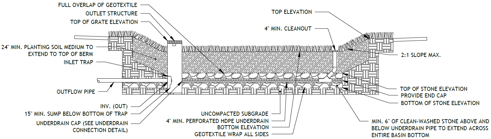
Figure 4.1‑5: Underdrain connection standard detail
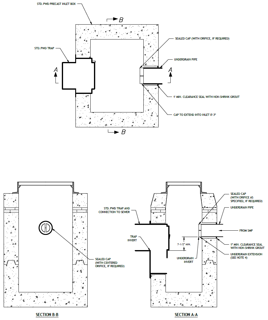
(The designer is referred to Appendix L to download Standard Detail CAD files.)
4.1.4 Bioinfiltration/bioretention material standards
Pretreatment material standards
- The designer is referred to Section 4.10, Pretreatment, for information on materials standards for pretreatment systems.
Inlet control material standards
- The designer is referred to Section 4.11, Inlet Controls, for information on material standards for inlet control systems.
Storage area material standards
- Stone designed for stormwater storage must be uniformly graded, crushed, clean-washed stone. PWD defines “clean-washed” as having less than 0.5% wash loss, by mass, when tested per American Association of State Highway and Transportation Officials (AASHTO) T-11 wash loss test. AASHTO No. 3 and No. 57 stone can meet this specification.
- Sand, if used, must be AASHTO M‑6 or American Society of Testing and Materials (ASTM) C‑33 sand and must have a grain size of 0.02 to 0.04 inches.
- Planting Soil Medium
- Planting soil should meet all the specifications listed below and should be a fertile, natural soil, free from large stones, roots, sticks, clods, plants, peat, sod, pockets of coarse sand, pavement and building debris, glass, noxious weeds including invasive species, infestations of undesirable organisms and disease-causing pathogens, and other extraneous materials harmful to plant growth.
- The texture of planting soil should conform to the classification within the United States Department of Agriculture triangle for Sandy Loam or Loamy Sand. Planting soil should be a mixture of sand, silt, and clay particles as required to meet the classification. Ranges of particle size distribution, as determined by pipette method in compliance with ASTM F-1632, are as follows:
- Sand (0.05 to 2.0 mm): 50 – 85%
- Silt (0.002 to 0.05mm): 40% maximum
- Clay (less than 0.002mm): 10% maximum
- Gravel (2.0 to 12.7 mm): 15% maximum
- Planting soil should be screened and free of stones larger than a half‑inch (12.7 millimeters) in any dimension. No more than 10% of the soil volume should be composed of soil peds greater than one inch.
- Clods, or natural clumps of soils, greater than three inches in any dimension should be absent from the planting soil. Small clods ranging from one to three inches and peds, natural soil clumps under one inch in any dimension, may be present but should not make up more than 10% of the soil by volume.
- The pH of the planting soil should have a range of 5.8 to 7.1.
- Soluble salts should be less than 2.0 mmhos/cm (dS/m), typically as measured by 1:2 soil-water ratio basic soil salinity testing. Sodic soils (Exchangeable Sodium Percentage greater than 15 and/or Sodium Adsorption Ratio greater than 13) are not acceptable for use regardless of amendment.
- Organic content of planting soil should have a range of 3% to 15% by weight, as determined by loss on ignition (ASTM D2974). To adjust organic content, planting soil may be amended, prior to placing and final grading, with the addition of organic compost.
- Mulch, if used, must be free of weeds and must consist of aged, double-shredded hardwood bark mulch or leaf mulch that has been shredded sufficiently to limit risk of matting, which can limit surface infiltration rates. For hydroseeding, paper mulch may be used. Approved mulching materials include organic materials such as compost, bark mulch, leaves, as well as small river gravel, pumice, or other inert materials. Grass clippings should not be used as mulch.
- Geotextile must consist of polypropylene fibers and meet the following specifications (AASHTO Class 1 or Class 2 geotextile is recommended):
- Grab Tensile Strength (ASTM-D4632): ≥ 205 lbs
- CBR Puncture Strength (ASTM-D6241): ≥ 500 lbs
- Flow Rate (ASTM-D4491): ≥ 95 gal/min/ft2
- UV Resistance after 500 hours (ASTM-D4355): ≥ 70%
- Tear Resistance (ASTM-D4533): ≥ 80 lbs
- Heat-set or heat-calendared fabrics are not permitted.
Vegetation material standards
- Trees and shrubs must be freshly dug and grown in accordance with good nursery practice.
- Perennials and herbaceous plants must be healthy, well-rooted specimens.
- A native grass/wildflower seed mix can be used as an alternative to groundcover planting. Seed mix must be free of weed seeds.
- Use of invasive plants is not permitted. All plants and trees must be appropriate and compatible with soil, hydrologic, light, and other site conditions. The designer is referred to Appendix I for plant lists.
Outlet control material standards
- Underdrains must be made of continuously perforated high-density polyethylene (HDPE) plastic piping with a smooth interior and a minimum inner diameter of four inches. HDPE pipe must meet the specifications of AASHTO M252, Type S or AASHTO M294, Type S.
- The designer is referred to Section 4.12, Outlet Controls, for more information on material standards for outlet control systems.
Inspection and maintenance access material standards
- Cleanouts must be made of material with a smooth interior having a minimum inner diameter of six inches. If the connecting pipe is eight inches in diameter or larger, then the cleanout must be eight inches in diameter.
4.1.5 Bioinfiltration/bioretention construction guidance
Careful consideration of issues like soil compaction, infiltration performance, and sediment control are critical to ensure proper bioinfiltration/bioretention functionality and reduce long-term maintenance needs. Poor oversight of construction activities could result in the need for substantial reconstruction to address performance problems.
- Provide erosion and sedimentation control protection on the site such that construction runoff is directed away from the proposed bioinfiltration/bioretention location. The designer is referred to the latest edition of the PA DEP Erosion and Sediment Pollution Control Program Manual for information on design standards for erosion and sedimentation control practices.
- Bioinfiltration areas must be physically marked prior to any land-disturbing activities to avoid soil disturbance and compaction during construction. Install construction fencing around bioinfiltration areas.
- Proposed bioretention areas may be used as sediment traps during construction. Bioinfiltration areas may not be used as sediment traps during construction, unless at least three feet of soil are left in place while the area is serving as a sediment trap and subsequently removed during construction after the contributing drainage areas have been stabilized.
- Complete site elevation grading and stabilize the soil disturbed within the limits of disturbance. Do not finalize bioinfiltration/bioretention excavation and construction until the drainage area is fully stabilized.
- Excavate bioinfiltration/bioretention area to proposed invert depth and manually scarify the in situ soils at the base of the excavation. Do not compact in situ soils. Heavy equipment must not be used within the bioinfiltration area. All equipment must be kept out of the excavated area to the maximum extent possible. The use of machinery to load any proposed stone from outside of the basin footprint is recommended. Rock construction entrances must not be located on top of areas proposed for infiltration practices. Heavy equipment exclusion zones must be established to avoid compaction of the infiltration area during construction. Excavate bioinfiltration/bioretention area to proposed invert depth and manually scarify the in situ soils at the base of the excavation. Do not compact in situ soils. Heavy equipment must not be used within the bioinfiltration area. All equipment must be kept out of the excavated area to the maximum extent possible. The use of machinery to load any proposed stone from outside of the basin footprint is recommended. Rock construction entrances must not be located on top of areas proposed for infiltration practices. Heavy equipment exclusion zones must be established to avoid compaction of the infiltration area during construction.
- Perform infiltration testing (if testing was deferred until construction). The designer is referred to Section 3.3 for guidance on infiltration testing procedures.
- For bioinfiltration SMPs, where infiltration is feasible, ensure underdrains are equipped with a water-tight end cap within the outlet control structure.
- For bioretention basins, where infiltration is infeasible, convert the underdrain to a flow-regulating underdrain by drilling an appropriately-sized orifice in the center of a water-tight underdrain cap center within the outlet control structure.
- Place impervious liner, if needed within a bioretention basin, ensuring continuous contact with subgrade. Extreme care should be taken during installation of a geomembrane liner so that no damage is done to any part of the material. Construction equipment, gasoline driven generators, or cans of gas or solvent must not be placed on the geomembrane material. The geomembrane material must not be used as a work area to prepare patches or to store tools and supplies. Temporary wind anchorage by means of sandbags or tires must be provided during geomembrane installation. Nails, rebar, wire ties, or other metal materials shall not be used to hold geomembrane in position. Geomembrane seaming must be performed in accordance with ASTM D7408 (PVC) and ASTM D8580 (LLDPE, PP). Non-destructive and destructive testing of geomembrane seaming must be performed in accordance with ASTM D7700. Mechanical attachment of geomembrane to pipe penetrations or structures must be installed in accordance with ASTM D6497/D6497M‑02. Placement of overlying material must be performed in a manner that will not damage the geomembrane. Excessive wrinkling of the geomembrane must be prevented prior to or while covering the geomembrane, ensuring no permanent folds or wrinkles in the liner. Any damage to the geosynthetic material must be repaired immediately.
- Any stone within the infiltration SMP must remain free of sediment and meet the washed stone specification found above. If sediment enters the stone, the contractor may be required to remove the sediment and replace with clean washed stone.
- Place filter fabric or pea gravel filter, then place the stone, and set the underdrain according to the plans.
- Backfill the excavated area as soon as the subgrade preparation is complete to avoid accumulation of debris. Place bioinfiltration/bioretention soil in 12- to 18‑inch lifts and tamp lightly by hand or compact by watering each lift. Ensure backfill process does not disrupt pipe placement and configuration. Slight overfilling might be necessary to account for settlement. Pre-soak the soil at least one day prior to final grading and landscaping to allow for settlement.
- After allowing for settlement, complete final grading within about two inches of the proposed design elevations, leaving space for top dressing of mulch or mulch/compost blend.
- Seed and plant vegetation as indicated on the plans and specifications.
- Place mulch and hand grade to final elevations.
- Install energy dissipaters as specified on the plans, if applicable.
- Water vegetation at the end of each day for two weeks after planting is completed.
- Water vegetation regularly during first year to ensure successful establishment.
4.1.6 Bioinfiltration/bioretention maintenance guidance
Bioinfiltration/bioretention maintenance activities focus largely on maintaining infiltration capacity and the health of vegetation. During periods of extended drought, bioinfiltration/bioretention SMPs may require watering approximately every ten days.
General recommended maintenance activities for bioinfiltration/bioretention SMPs are summarized in Table 4.1‑5 below
Table 4.1‑5: Bioinfiltration/bioretention maintenance guidelines
| Early maintenance activity | Frequency |
|---|---|
| Water vegetation at the end of each day for two weeks after planting is completed. | Daily for two weeks after installation |
| Water vegetation regularly to ensure successful establishment after planting. | Every four days during periods of four or more days without rain, June through August for the first year after installation |
| Inspect vegetation for signs of disease or distress. | Biweekly for the first year after installation |
| Inspect inlet controls, outlet structures, and storage areas for trash and sediment accumulation. | Monthly for the first year after installation to determine ongoing maintenance frequency |
| Ongoing maintenance activity | Frequency |
|---|---|
| Remulch void areas. | As needed |
| Treat diseased trees and shrubs. | As needed |
| Keep overflow free and clear of leaves. | As needed |
| Remove any invasive vegetation by hand. | As needed |
| Thin any overgrown areas of vegetation. | As needed |
| Inspect soil and repair eroded areas. | Monthly |
| Remove litter and debris. | Monthly |
| Clear leaves and debris from overflow. | Monthly |
| Empty filter bags for pretreatment devices. Ensure filter bag is installed properly. | Monthly |
| Inspect trees and shrubs to evaluate health, replacing if necessary. | Quarterly |
| Inspect underdrain cleanouts. | Quarterly |
| Ensure river rock layout is sufficient to dissipate flow and check for downstream erosion. Replace river rock as necessary and repair erosion issues. | Quarterly |
| Add additional mulch. | Quarterly |
| Inspect for sediment build-up, erosion, and vegetative conditions. Remove sediment buildup, stabilize eroded areas and add vegetation if necessary. | Quarterly |
| Evaluate the drain down time of the SMP after a storm of at least one inch in no more than 24‑hours to ensure an SMP drain down time of less than 72 hours. | Ongoing |
| Maintain records of all inspections and maintenance activity. | Ongoing |
The designer is referred to Section 4.10, Pretreatment, Section 4.11, Inlet Controls, Section 4.12, Outlet Controls, and Section 4.13, Landscaping, for information on maintenance guidance for pretreatment, inlet controls, outlet controls, and landscaping.