Section 3.2 contains a significant amount of design guidance that the designer should use to integrate robust and cost-effective stormwater management into site designs in ways that achieve the Philadelphia Water Department’s (PWD’s) key stormwater management goals of minimizing the harmful effects of flooding and maintaining the health of Philadelphia’s streams and rivers. Additionally, this section contains general requirements and standards of which the designer must be aware.
3.2.1 Major SMP Types
Infiltrating SMPs
Infiltrating stormwater management practices (SMPs), such as porous pavement, subsurface infiltration, and bioinfiltration practices, manage stormwater by infiltrating it into the ground. The designer is required to use infiltrating practices to meet the Water Quality requirement unless infiltration is found to be infeasible. All infiltrating practices are considered pollutant-reducing.
Slow Release SMPs
Slow release SMPs detain and slowly release stormwater over time. Some slow release practices are inherently pollutant-reducing practices (if stormwater is passed through a soil/vegetation/media complex), while others may need to be designed in series with an additional pollutant-reducing SMP.
Pollutant-Reducing SMPs
On sites where infiltration is not feasible, directly connected impervious area (DCIA) must be routed to an acceptable pollutant-reducing practice. Table 3.1‑3 in Section 3.1.7 presents the non-infiltrating SMPs that PWD currently accepts as pollutant-reducing practices. For detailed information and design guidelines for individual SMPs, the designer is referred to Chapter 4. Alternative pollutant-reducing practices may be proposed and will be reviewed on a case-by-case basis. Pollutant-reducing practices include all infiltrating practices and some slow release practices.
Vegetated SMPs
Vegetated practices include vegetation as a significant or dominant component within the storage area and include bioinfiltration/bioretention basins, ponds and wet basins, green roofs, and vegetated media filters.
Non-Vegetated SMPs
Non-vegetated practices include all subsurface practices, blue roofs, porous pavement, media filters, and cisterns, and do not have significant vegetative components.
3.2.2 SMP Hierarchy and Selection Process
Download a summary of the SMP Hierarchy guidance, with quick reference information for clients and developers:
The process of selecting the right SMPs for a site is complex and can be challenging, particularly for constrained sites. PWD accepts many different SMPs and offers approaches such as SMPs in series and Stormwater Management Banking and Trading that provide the designer flexibility in fitting SMPs into challenging project sites. During the SMP selection and conceptual design process, the designer will select and perform an initial layout of SMPs, incorporating site assessment data; an understanding of remaining stormwater management requirements (after accounting for non-structural design and disconnected impervious cover (DIC) strategies); PWD’s SMP preferences; and other factors such as aesthetics, cost, and maintenance requirements. This SMP selection and initial layout process should be performed prior to the finalization of the development site layout, such that the site layout can be revised, if needed, based on SMP requirements. Typically, the designer will perform initial SMP selection and conceptual design prior to the submission of the Conceptual Review Phase Submission Package (Section 2.3) or a Stormwater Grant Application for Stormwater Retrofit projects seeking Stormwater Grant funding.
PWD requires that infiltrating SMPs be used to meet the Water Quality requirement unless the designer demonstrates that infiltration is not feasible. Infiltration testing and soil characterization procedures are outlined in Section 3.3. In many cases, infiltration testing will not be performed until the initial layout of SMPs has been completed. While it is generally prudent to conduct this testing as soon as SMP footprints and depths have been estimated, infiltration testing is not required to be performed during conceptual design. By performing a site assessment and stormwater management opportunities and constraints analysis in accordance with Section 3.1, the designer can reduce the likelihood that a properly conducted infiltration and soil characterization plan (Section 3.3.1) will uncover non-infiltrating subsurface conditions at the SMPs’ footprints laid out during SMP selection and conceptual design. A site assessment and opportunities/constraints analysis will do so by screening out locations, such as areas with documented high seasonal groundwater, shallow bedrock, clay, or other limiting soil layers that may preclude infiltration, and steering the conceptual SMP layout toward areas more likely to support infiltration.
PWD recommends a three-step process for selecting and advancing SMP design through the conceptual design phase.
Step 1 – Understanding the Options: The SMP Hierarchy
SMPs can differ greatly from each other in terms of cost, function, and applicability to different types of sites. The designer is encouraged to thoroughly review the SMP-specific guidance provided in Chapter 4 when selecting SMPs. The SMP One-Sheets at the beginning of each SMP Chapter should help in understanding the potential for using each SMP type to meet the various Stormwater Regulations.
The SMP Hierarchy is a tool developed to help PWD understand and communicate the order of PWD’s preference for all SMPs. This tool has allowed PWD to formulate incentive-based policies that promote the use of high-performance and cost-effective stormwater management approaches that more effectively achieve the goals of the Green City, Clean Waters program. Similarly, the Hierarchy provides a clear reference point for the private development community to understand which SMPs are most preferred by PWD. Specifically, the Hierarchy seeks to promote practices that do the following:
- Reduce stormwater and pollutants entering and leaving the PWD collection system;
- Are likely to be maintained and have indicated longevity in previous installations; and
- Provide vegetation to create a greener city.
Ranking Criteria
The criteria used to rank the SMPs reflect a wide range of characteristics, such as water quality and quantity performance, space requirements, construction and maintenance costs, likeliness of failure, and triple bottom line performance. As a result, the Hierarchy reflects preferences based on stormwater management performance, constructability, and longevity. Table 3.2‑1 outlines the main criteria considered when ranking SMPs in order of their relative weight. The SMP One-Sheet at the beginning of each SMP Section in Chapter 4 displays its relative performance level for each attribute.
Table 3.2‑1: SMP Hierarchy Ranking Criteria
| SMP Hierarchy Ranking Criteria | |
|---|---|
| Infiltration and Volume Reduction | The SMP’s ability to infiltrate or reduce the Water Quality volume (WQv) |
| Effluent Pollutant Load | The typical annual mass of total suspended solids (TSS) in the SMP’s effluent runoff (total annual mass of TSS, accumulated at a point of analysis downstream of the SMP). Annual TSS mass is computed by considering the SMP to be managing one acre of DCIA with effluent event mean concentrations of TSS based on data from the International Stormwater BMP Database. |
| Likeliness of Failure | The relative likelihood that the SMP will fail to operate and will fail to be repaired so that it functions as designed over a unit period of time based on observations at a program level. |
| Construction Costs | The marginal redevelopment implementation costs associated with the construction of the SMP per acre of DCIA treated. As defined in the Long-Term Control Plan Update (LTCPU), marginal redevelopment cost is considered the cost beyond traditional measures to implement an SMP approach, assuming that redevelopment is already taking place. SMP costs were derived from the construction cost analysis and reference cost assessment prepared for the LTCPU, with updated unit costs. |
| Evapotranspiration | The SMP’s ability to manage stormwater runoff via evapotranspiration (ET). Each SMP is evaluated based on the characteristics of the surface area available for ET and any enhancement factors (vegetation). These vary by typical vegetation cover type and density, as well as any non-vegetative evaporation pathways (i.e., surface water and void spaces). |
| Triple Bottom Line | The SMP’s ability to provide social, environmental, and economic benefits (land value, energy efficiency, etc.). |
| Water Quality Rate Control | The ability of an SMP to reduce the release rate of the WQv to not exceed the maximum release rate. |
| Large Storm Rate Control | The ability of an SMP sized for Water Quality compliance to reduce the discharge rate of large runoff events and to be resized to manage large storm events, which is helpful in complying with the Flood Control and PHS Release Rate requirements. |
| Operations and Maintenance (O&M) Costs | The annual costs associated with O&M activities for the SMP. They were derived from the maintenance cost analysis prepared for the LTCPU. |
| Building Footprint Encroachment | Encroachment onto site area that could otherwise be used for building footprint. |
| Ground-Level Encroachment | Encroachment onto potential usable, open space on the ground-level surface of the site. |
The SMP Hierarchy is shown below in Table 3.2‑2. All SMPs are classified as one of three preference levels: Highest, Medium, and Lowest.
Highest-Preference SMPs
The highest-ranking SMPs include bioinfiltration, bioretention, permeable pavers, reinforced turf, and green roofs. Bioinfiltration is ranked highest for its ability to infiltrate stormwater and provide triple bottom line benefits while being cost effective and long-lasting. Similarly, bioretention is ranked very high, reflecting its ability to settle suspended solids and cycle nutrients via plant uptake. As bioinfiltration and bioretention basins are both vegetated, they also have the potential for mitigating the urban heat island effect as well as reducing pollutant loads within the City’s waterways, which are both important contributions to help limit the predicted impacts on the City due to a warming climate.
The designer is encouraged to incorporate SMPs from this Hierarchy tier into their stormwater management design. As discussed in Section 2.4, projects that manage stormwater with SMPs only in this category are eligible for a Surface Green Review. Advantages of a Surface Green Review include a shorter (five-day) Post‑Construction Stormwater Management Plan (PCSMP) Review Phase and the option to postpone infiltration testing until construction.
Medium-Preference SMPs
SMPs considered to have medium preference (subsurface infiltration, cisterns, blue roofs, porous asphalt, porous concrete, and ponds and wet basins) tend to efficiently manage stormwater via infiltration, volume reduction, or detention. These SMPs often provide fewer triple bottom line benefits and may not last as long as more highly preferred SMPs.
Lowest-Preference SMPs
The least-preferred SMPs in the Hierarchy (subsurface detention with vegetated media filters, subsurface detention with roof runoff isolation, subsurface detention with media filters, vegetated media filters, and media filters) are non-infiltrating and generally provide little, to no, triple bottom line benefits. Additionally, the SMPs in this tier tend to have relatively high operations and maintenance (O&M) costs and may malfunction more frequently than other SMPs.
Table 3.2‑2: SMP Hierarchy
Step 2 –Determining Residual Management Requirements
The designer may be able to satisfy some or all of the Stormwater Regulations using non-structural design or DIC strategies. Prior to considering the use of SMPs, the designer must develop a quantitative understanding of the remaining stormwater management needs with respect to each of the Post‑Construction Stormwater Management Criteria: Water Quality, Channel Protection, Flood Control, and Public Health and Safety Release Rate. Following the evaluation of non-structural and disconnection options, the designer must determine the following prior to proceeding to the SMP design stage:
- Total remaining DCIA to be treated and associated Water Quality volume (WQv)
- Peak flow attenuation required for all site DCIA, for the Channel Protection requirement, if applicable; and
- Total peak flow comparison from predevelopment to post-development conditions for each point of interest, for the Flood Control requirement, if applicable.
Step 3 – SMP Placement and Layout
Some sites will offer numerous options for locating SMPs (on rooftops, on the ground surface, or underground), while other sites, particularly “full build-out” sites (where ground-level open space is not available in the proposed site layout), will have fewer options for SMP placement. PWD encourages the designer to incorporate ground-level vegetated SMPs on sites wherever possible, resorting to subsurface SMPs only when other options have been exhausted. The designer should approach the SMP placement and layout process after becoming thoroughly familiar with the characteristics, advantages, limitations, and appropriate uses of acceptable SMPs. The designer should choose SMPs per the SMP Hierarchy presented above, exhausting opportunities for preferred practices prior to considering lower priority practices.
The following guidelines and suggestions are provided to assist the designer with selecting and arranging SMPs.
- Assessing Space Constraints – SMPs rely on storage volume to achieve performance. The availability of space for SMPs will often dictate the location and type of SMPs that can work on a site. Considering SMP placement early in the design process is critical to ensuring that sufficient space for incorporating SMPs, particularly ground-level SMPs, is present. The designer should calculate approximate design requirements (e.g., total required storage volume) to allocate space for stormwater management within the site layout. If sufficient space is unavailable for incorporating surface-vegetated practices, the designer may need to consider alternatives such as porous pavement, or other SMPs, proceeding down the SMP Hierarchy. The use of SMPs in series, Stormwater Management Banking and Trading, and/or adding subsurface storage to a bioretention system can help the designer maximize the use of surface-vegetated SMPs, even on constrained sites.
- Creating On-Site Amenities – SMPs such as green roofs and bioinfiltration/bioretention basins can provide on-site greening, as vegetated features can act as an aesthetic amenity, particularly for residential and commercial retail sites. Bioinfiltration/bioretention SMPs should be designed in conjunction with other desired and required landscaping.
- Choosing Areas with Infiltration Potential – Although the exact infiltration rate at a particular location within a site is not generally known during the Conceptual Review Phase, the designer should use existing information to locate SMPs in areas that have a strong potential for infiltration. Much of this information, such as United States Department of Agriculture (USDA) Hydrologic Soil Maps, existing geotechnical reports, existing soil investigation reports, drainage feature mapping, topographic mapping, information on existing site drainage issues, and data on high seasonal groundwater, will have been compiled during initial site assessment activities as described in Section 3.1.1 and Section 3.1.2, and must be used for this purpose.
- Prioritizing Low-Lying Areas – Surface-level SMPs should be located on lower portions of a site, where stormwater can be gravity-fed from DCIA to the SMPs without making the SMPs excessively deep. These low-lying areas should be prioritized for stormwater management early in the site design process.
- Providing Downstream Points of Relief – SMPs need to provide gravity drainage for both overflow structures and underdrains. SMP elevations must not be too low to preclude tying in underdrains and overflow structures to a downstream point of relief (e.g., sewer or receiving water)
- Minimizing Conveyance Requirements – SMPs are less costly and easier to maintain if the designer reduces the amount of collection and distribution piping. Opportunities to sheet flow stormwater from DCIA to SMPs, or to use surface conveyance systems like swales to bring stormwater into SMPs, should be sought. In some cases, the designer may be able to use natural drainage features to convey stormwater with little additional cost.
- Avoiding Utilities – Careful mapping of surface and subsurface utilities on-site is necessary to reduce conflicts and the potential for relocating of existing utilities. A designer can view PWD utility records by contacting PA One Call and PWD Water Transport Records Unit.
- Avoiding Sensitive Features – SMPs should be placed in locations that avoid sensitive features, such as mature tree stands, wetlands, steep slopes, and floodplains, and constraints, such as shallow bedrock and groundwater. These areas will have been mapped during the site assessment process in Section 3.1.1 and Section 3.1.2. Many of these areas are regulated by State and Federal agencies and/or City ordinances.
- Providing Maintenance Access – Locating SMPs in areas where they can be easily accessed for maintenance is an important design consideration. Vehicular access routes, if needed for sediment removal, should be considered.
- Avoiding Hotspots and Contamination – Locating SMPs away from hotspots and areas of known contamination is always a good idea. Location of infiltrating SMPs within contaminated areas is not permitted. The designer is referred to the hotspot investigation procedures in Section 3.1.1 for more information. During this phase, a preliminary investigation of likely hotspots is suggested. During detailed design, more exhaustive characterization of soil contamination issues may be required for individual SMP sites to determine infiltration feasibility.
- Avoiding Unstable Fill – Many areas of Philadelphia are underlain by historic fill, which can be loose or unstable. The designer is advised to identify areas of unstable fill through geophysical methods, exploratory geotechnical testing, or historic mapping to avoid these areas where possible.
- Maintaining Sight Lines – Clear lines of sight are critical for pedestrian and vehicular safety. SMPs should be placed so as not to impair lines of sight, and the designer must consider full grow-out condition for vegetation when assessing sight line issues.
- Ensuring Safety – Many SMPs contain features such as ponded water that could be unsafe, particularly for vulnerable populations, such as young children. The designer should consider locating SMPs with ponded water away from play-yards, playgrounds, or other areas where children are playing, or installing fencing or other features to limit interaction with the system.
- Considering Appropriate Conditions for Vegetated SMPs – Some variables to consider include amount of sunlight received and solar orientation, wind speed and direction, temperature gain, and surface character. For example, sites facing northeast receive morning sun and tend to be cooler and wetter than those facing southwest and runoff from asphalt will be hotter than that from concrete. Combinations of these variables create different micro-climates and should be taken into account when placing the SMP and selecting plants.
3.2.3 Placing SMPs in Series
Many of the SMPs discussed in this Manual provide both Water Quality treatment and rate control. Some SMPs provide only rate control. The designer must keep in mind that some SMPs cannot fully meet all applicable Stormwater Regulations on their own, and a network of SMPs can be used to meet the Stormwater Regulations for a given site. For example, peak rate control for Flood Control compliance could be progressively achieved through flow attenuation in a series of smaller, linked SMPs. Many of these SMPs could also be used to meet the Water Quality requirement by providing cumulative static storage equal to the contributing WQv. In addition, non-pollutant-reducing practices, such as subsurface detention systems, can be used to meet the Water Quality slow release rate requirement, Channel Protection, and Flood Control requirements, but they cannot be used to meet the Water Quality pollutant-reduction requirement. In other cases, space constraints may preclude the ability to comply with the Stormwater Regulations using only one SMP.
While it is generally more cost effective, efficient, and easier to meet the Stormwater Regulations using as few SMPs as possible, to provide more flexibility, PWD allows the designer to use approaches that achieve compliance through the use of multiple SMPs connected in series. Placing SMPs in series allows the designer to minimize the disrupted space, limit the construction or maintenance costs of a system, or meet the Stormwater Regulations on a crowded or complex site. Particular approaches will vary by site, and the designer is encouraged to use creativity to combine SMPs in ways that achieve site-wide compliance. Some examples of these approaches are discussed below.
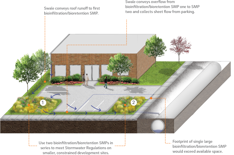
Multiple Small Bioinfiltration/Bioretention SMPs
A series of smaller bioinfiltration/bioretention SMPs can be placed within small landscaped areas in lieu of a single large bioinfiltration/bioretention SMP. This approach can be effective for promoting vegetated surface SMPs within constrained sites. Figure 3.2‑1 illustrates this approach.
Figure 3.2‑1: SMPs in Series Example #1 – Multiple Small Bioinfiltration/Bioretention SMPs
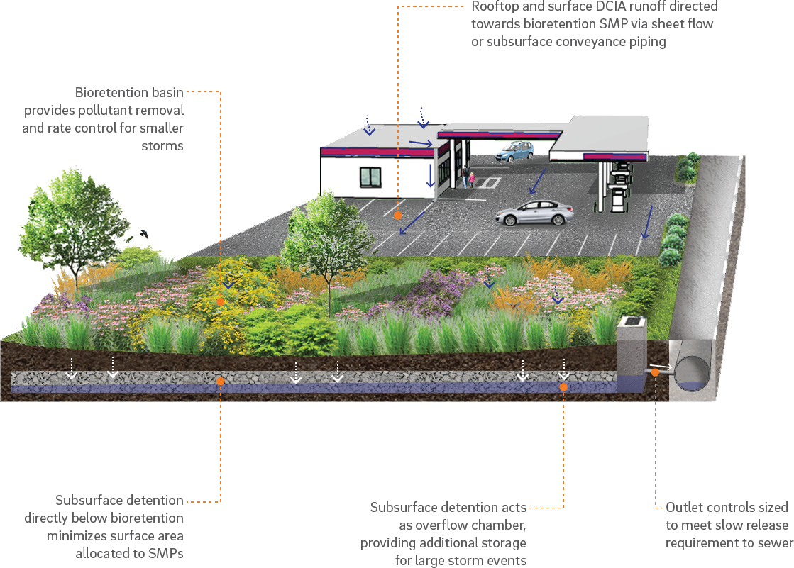
Bioretention with Subsurface Detention
Bioretention systems are particularly effective for managing the WQv. They provide treatment and rate control, but may not provide enough storage to meet the Flood Control or PHS Release Rate requirements, if applicable. A bioretention basin installed directly over a subsurface detention basin provides a number of benefits. The bioretention basin is relatively easy to maintain and is a pollutant-reducing practice. The subsurface detention basin provides effective rate control for small and large storms. This combination allows the subsurface detention basin to act as an overflow chamber for large runoff volumes generated by large storms. The bioretention and subsurface detention basin in series can reduce the amount of usable surface area disrupted while meeting the Stormwater Regulations. Figure 3.2‑2 illustrates this approach.
Figure 3.2‑2: SMPs in Series Example #2 – Bioretention with Subsurface Detention
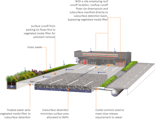
Vegetated Media Filter with Subsurface Detention
A subsurface detention basin with an upstream vegetated media filter is a combination of SMPs that can be used to meet the Water Quality slow release and pollutant-reduction requirements on sites that cannot infiltrate in the combined sewer area. The subsurface detention basin is a compact SMP that can be installed below a parking lot to limit the amount of usable surface that is disrupted. With a site employing the pollutant-reducing practice of roof runoff isolation, runoff from rooftop DCIA can be sent directly to the subsurface detention basin without any filtering treatment. A vegetated media filter can then be installed on-site to capture the WQv from surface-level DCIA and treat the runoff before discharging the treated volume to the subsurface detention basin. Figure 3.2‑3 illustrates this approach.
Figure 3.2‑3: SMPs in Series Example #3 – Vegetated Media Filter with Subsurface Detention
The following requirements apply to SMPs placed in series:
- SMPs can be placed in series to achieve rate control for the Stormwater Regulations. The designer does not have to demonstrate compliance with rate control requirements at the discharge point of each SMP, as long as rate control can be provided at the downstream-most point of the SMP series, prior to discharge to PWD sewer or receiving water.
- When complying with the Water Quality requirement, cumulative static storage volume may be provided within a connected series of SMPs, rather than any single SMP.
- Individual SMPs within a series must be designed in full accordance with design requirements provided in Chapter 4. For example, each bioretention system in a series must individually meet loading ratio and drain down time requirements.
- When using SMP in series, upstream flow splitters may be used to direct larger events around Water Quality SMPs, such as bioretention systems, to larger Flood Control SMPs.
3.2.4 Stormwater Management Banking and Trading
Download summaries of Stormwater Management Banking and Trading guidance, with quick reference information for clients and developers:
Stormwater Management Banking and Trading One-Sheet
Stormwater Management Banking and Trading: Same Parcel Trading One-Sheet
PWD generally requires full compliance with the Stormwater Regulations for each point at which stormwater leaving the site is discharged to either a receiving water or PWD sewer. SMPs must be provided as appropriate to achieve compliance at each of these locations. If site constraints or existing conditions will prevent a development project from complying fully with the Stormwater Regulations, or if placement of an SMP could result in a potential environmental or safety hazard, the designer may consider Stormwater Management Banking and Trading. Stormwater Management Banking and Trading allow a project to be flexible in the placement of required SMPs. Proposals to use banking and trading methods are considered by PWD on a case-by-case basis, and a pre-application meeting is highly recommended.
Stormwater Management Banking refers to the oversizing of SMPs to be used toward regulatory compliance for future development improvements. To qualify for Stormwater Management Banking, the SMPs must be constructed prior to the associated development project. When Stormwater Management Banking is proposed, each phase of work will be held to the Stormwater Regulations in place at the time of the Existing Resources and Site Analysis (ERSA) Application. Furthermore, the specific performance of the SMP is banked, not the area managed. Future projects must meet the regulations that apply at that time, which may reduce the amount of area for which the banked performance can be traded.
Stormwater Management Trading refers to the siting of SMPs to manage impervious area not associated with the proposed development improvement, whereas the DCIA associated with the development project is traded for an equivalent managed area. The SMPs can be located on the same parcel as the development project but must manage area outside of the development project’s limit of disturbance. Area proposed for trade must be unmanaged in the pre-development condition unless the area has been previously identified as part of a Stormwater Management Banking agreement.
Stormwater Management Banking and Trading is only relevant to projects required to comply with Stormwater Regulations. Stormwater Retrofits have differing management strategies, as discussed in Section 1.3.
Banking and Trading SMP Standards
- SMP(s) must achieve the same regulatory standard (Water Quality and Channel Protection) as if it were directly managing stormwater from the proposed development project.
- Banking and trading methods are not permitted to be used to comply with Flood Control.
- SMP(s) located within the same sewershed are preferred.
- Applicants who wish to engage in large scale Stormwater Management Banking and Trading that involves multiple parcels and/or property owners over a large area must provide a formal agreement that involves all parties and is approved by PWD. The parcel(s) containing the regulated improvement and the SMP(s) will be subject to Post‑Construction Stormwater Management (PCSM) Requirements, including an O&M Agreement to be recorded to the property deed(s).
- Applicants must provide sufficient written justification in their PCSMP Report for proposing a banking or trading management solution, including reasons why management of the regulated area(s) is not feasible and why PWD may benefit from the proposal. A short explanation should also be included in the ERSA Application.
- SMP(s) must manage an area equal to or greater than the unmanaged area and produce an equivalent pollutant load. For example, PWD will not approve a trade of unmanaged impervious parking lot with existing roof area because the total pollutant load from the trade surfaces is not equivalent.
Submission Package components for Stormwater Management Banking and Trading are no different from typical submissions. The designer, however, must clearly identify the banking or trading strategy on all plans and reports in the Submission Package. This information can be easily conveyed as a table; an example of which is provided below:
| Total LOD | 18,000 SF |
| On-site LOD | 17,000 SF |
| Impervious Area Within On-site LOD | 16,500 SF |
| Managed DCIA (i.e. DCIA routed to SMP) Within On-site LOD | 12,400 SF |
| DIC Area Within On-site LOD | 600 SF |
| Remaining Unmanaged DCIA Within On-site LOD (e.g. parking lot runoff) | 3,500 SF |
| Acceptable Trade Area (i.e. managed impervious area) outside of LOD | ≥ 3,500 SF of surface-level cover |
Additionally, if the designer believes that Stormwater Management Banking or Trading will be necessary to meet the Stormwater Regulations, they are encouraged to discuss this during the Conceptual Review Phase.
Understanding the limit of disturbance is key to proposing a trade approach for regulatory compliance. The existing impervious area to be managed for trade must remain outside the LOD throughout construction. For example, depaving or otherwise converting an existing impervious surface to pervious cover (such as converting a parking lot to porous pavement) cannot be used as trade as this activity increases the LOD, and the LOD boundary is used to determine the area applicable to the Stormwater Regulations. While this approach may help achieve an exemption from the Flood Control requirement (Section 1.2.1), it cannot be used for trade. Instead, the applicant should look at low impact options that will minimize the amount of existing impervious area to be disturbed, thus maximizing potential trade area.
The next section presents examples of how this may be achieved. The most common stormwater trade scenario is Same Parcel Trading, whereby SMPs are sited on a parcel that will manage DCIA not associated with the proposed improvement (outside the project’s LOD). The first scenario below presents an example of how Same Parcel Trading can be applied to, and benefit, a Redevelopment project.
Stormwater Management Trading Examples
Example of Same Parcel Trading – Food Distribution Facility
A property owner sought approval from the City to construct a new loading dock (Figure 3.2‑4, in red) at an existing food distribution facility. The only on-site area large enough on which to place an SMP was adjacent to the food warehouse, and the property owner had concerns about food contamination from wildlife attracted to a surface SMP. Therefore, the property owner considered subsurface SMPs that could be installed adjacent to the new loading dock; however, the disadvantages and constraints of subsurface SMPs in this application included the following:
- Relatively high cost to construct and maintain;
- Large space requirements to achieve controlled release standards, since soils near the loading dock were significantly compacted, precluding infiltration; and
- The need for the subsurface SMP design to accommodate heavy truck traffic, balancing SMP access points with heavy load-bearing surfaces.
Figure 3.2‑4: Same Parcel Trading Example
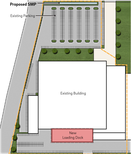
The property owner instead proposed an SMP (shown in blue) elsewhere on-site to manage existing undisturbed impervious area in the same sewershed. The benefits from this trade included the following:
- Less expensive SMP installation cost;
- Less disruption to distribution center’s operations during construction;
- Smaller SMP footprint located in better-infiltrating soils; and
- An above-ground SMP that can be more easily inspected and maintained.
Example of Same Owner Trading – Pharmacy and Parking Lot
A single party owned two parcels separated by the public right-of-way (ROW). The developer proposed construction of a pharmacy and a parking lot on one undeveloped parcel. The same developer owns an already developed parking lot across the street (presented post-development in Figure 3.2‑5).
Figure 3.2‑5: Same Owner Trading Example
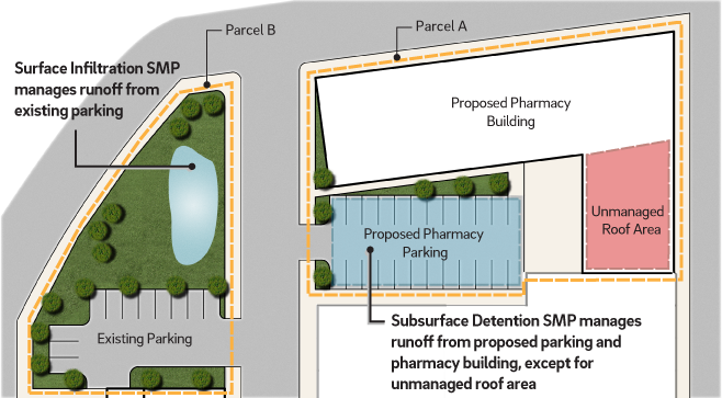
The site designer was able to manage all new impervious area proposed for Parcel A with a subsurface detention facility (shown in blue), except for a portion of the pharmacy roof area (shown in red). To meet Stormwater Regulations on Parcel A, the designer proposed to manage the existing parking lot on Parcel B with a surface infiltration SMP (shown in blue). The unmanaged pharmacy roof area discharges directly to the sewer system. The benefits from this trade included the following:
- Increased ability to fully use Parcel A;
- Less expensive SMP installation cost;
- An above-ground SMP that can be more easily inspected and maintained; and
- Limited reliance on underground SMPs.
Example of Same Owner Banking – Shopping Mall
A shopping mall owner proposed a series of improvements planned in phases. These included expansions to existing mall buildings, new standalone restaurants, and additional parking areas and driveways. Instead of designing and constructing SMPs for each individual improvement, the designer proposed a stormwater management banking scenario to construct a single SMP to serve all improvements.
Figure 3.2‑6: Same Owner Banking Example
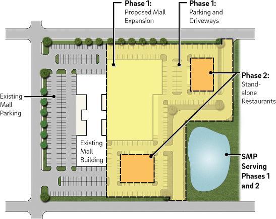
The designer first proposed an existing building expansion and additional parking areas and driveways under Phase 1 (shown in yellow on Figure 3.2‑6). Upon approval of this first phase, as well as a conceptual design of future standalone restaurant buildings under Phase 2 (shown in orange), PWD permitted the owner to install an oversized SMP (shown in blue) to manage these impervious surfaces. The owner then installed the remainder of the proposed improvements in Phase 2. The site designer directed all runoff to the single SMP that was constructed in Phase 1.
A benefit of this scenario was that the owner was able to obtain approvals quickly for the second phase of construction as the SMP was sized to meet the Stormwater Regulations for the entire project.
When Same Owner Banking is proposed, PWD will acknowledge the bank amount in terms of additional cubic feet capacity remaining in the SMP. This type of banking approach works best for projects where phases are planned in rapid succession, as each phase is held to the Stormwater Regulations in place at the time of its ERSA submission. Applicants who are interested in long term site master planning (which may occur over several years or decades, or between multiple parcels and property owners) are encouraged to discuss with PWD prior to implementation.
3.2.5 SMP Design Guidance and General Requirements
Once the initial selection of SMPs is complete, and PWD has approved the conceptual design, detailed design of SMP systems can be performed. Detailed design of SMPs and associated documentation will be submitted as part of the designer’s PCSMP Review Phase Submission Package to PWD. The designer is referred to Chapter 2 for details on preparing this Submission Package.
This Section provides guidance to the designer in the design of SMPs, outlining general requirements that apply to all SMPs. The designer is also referred to Chapter 4, which provides detailed guidance and requirements for specific SMPs.
Infiltration Testing and Waiver Requirements
A designer using SMPs to comply with the Water Quality requirement must use infiltration unless they can demonstrate that infiltration is infeasible. The designer must exhaust all possibilities for implementing infiltrating practices on proposed sites, including exploring alternative locations for infiltration facilities if initial locations are not found to be suitable for infiltration or over-excavating poorly infiltrating soils. The designer is referred to Section 3.3 for detailed information on performing infiltration tests, assessing infiltration feasibility, and preparing requests for infiltration waivers. If appropriate justification that contamination will preclude the site from infiltration is provided, an impervious liner must be incorporated into the SMP design.
Pretreatment Requirements
Pretreatment is critical for extending the design life and maximizing the performance of SMPs. The designer must provide adequate pretreatment for all SMPs. Appropriate pretreatment is based on a number of factors including SMP type, loading ratios, and drainage area characteristics. The designer is referred to Chapter 4 for more information on the design of pretreatment systems for specific SMPs and general pretreatment options.
Conveyance and Inlet and Outlet Control Requirements
Conveyance systems, including piping conveying stormwater to and from an SMP, and inlet and outlet control systems, which regulate the flow into and out of an SMP, are important aspects of SMP design. All storm sewer pipes must be designed to have adequate capacity to safely convey the ten-year storm without surcharging the crown of the pipe. Section 3.4.2 contains detailed guidance on storm sewer design and pipe capacity calculations, while Section 4.11 and Section 4.12 provide guidance on the design of inlet and outlet controls, respectively.
Sizing Requirements
Appropriate sizing is critical for SMP performance. The designer must incorporate several factors, including SMP type, function, maximum loading ratio requirements, release rate requirements, ponding depth, static storage requirements, media characteristics, freeboard requirements, and space limitations in determining appropriate SMP sizing. The designer is referred to the loading ratio requirements later in this Section and the SMP-specific sizing requirements in Chapter 4 to aid in determining appropriate SMP sizing.
Safe Overflow Requirements
Safe overflow must be provided for all SMPs. Runoff that overflows from an SMP (runoff that is not infiltrated or slow released) must be conveyed to receiving waters or sewers in a controlled manner that does not cause flooding, endanger public safety, or produce erosive conditions. Positive overflow must be provided for large storm events, up to and including the 100-year, 24-hour storm event, or, if the project is exempt from Flood Control, the ten-year, 24-hour storm.
Release Rate Requirements
For non-infiltrating practices in combined sewer areas, the designer must meet slow release rate requirements prior to discharge into PWD sewers or receiving waters. Typically, release rates for slow release systems are met using small orifices or other rate control devices. The designer is referred to Chapter 4 for specific information on designing outlet control systems.
3.2.6 Loading Ratio Requirements
Download a summary of the loading ratio requirements, with quick reference information for clients and developers:
Loading Ratio Requirements One-Sheet
Loading ratio is defined as the area of contributing DCIA divided by the bottom surface footprint of vegetated surface SMPs and the bottom footprint of infiltrating subsurface SMPs. The loading ratio is a tool that is used for sizing an SMP with consideration of acceptable sediment loading. It is a balancing point between maintenance requirements, performance requirements, and safety considerations. PWD’s loading ratios are used as maximum acceptable SMP sizes for stabilized sites that are appropriately maintained; they are not necessarily the recommended loading ratios. The maximum loading ratio for vegetated surface SMPs is 16:1. The maximum loading ratio for infiltrating subsurface SMPs is 10:1. Runoff that has been filtered through a soil profile should not be counted toward the subsurface loading ratio for SMPs in series.
| Loading Ratios | |
|---|---|
| Maximum Loading Ratios | Surface vegetated SMPs: 16:1 Subsurface infiltrating SMPs: 10:1 |
| Maintenance | Long-term maintenance is a fundamentally important piece of an SMP’s design. PWD’s loading ratios were selected with the assumption that the final site will be stabilized, and the SMP will be maintained at regular intervals. Surface SMPs with a 16:1 loading ratio will require frequent maintenance, including the removal and replacement of the top layer of soil along the bottom footprint of the SMP. |
| Safety | The larger the loading ratio, the deeper the SMP must become to store the required volume of water. A surface basin with a 16:1 loading ratio will have a maximum Water Quality storage depth of two feet, which limits the total water depth and the risks to public safety. |
| Performance | The loading ratio greatly affects the performance of infiltrating SMPs by determining the footprint available for infiltration. PWD requires that all SMPs drain down in no more than 72 hours, however owners may want their SMPs to drain more quickly, thus the loading ratio may need to be reduced to meet the performance goals for the system. For example, an SMP with a loading ratio of 16:1 and an infiltration rate of 0.4 inches/hour drains down in 60 hours; however, the site owner may not want ponded water on-site for 60 hours. |
| Limitations | The larger the loading ratio, the less redundancy there is in an SMP. The SMP designer should consider the causes of potential failure for their SMP and attempt to minimize their likelihood and their effects. For example, a small SMP with a large impervious drainage area has the potential to receive a significant volume of water and sediment in larger storm events, which could overwhelm and/or clog the small SMP. In this case, a larger basin footprint may be warranted to safely convey the extra volume.Subsurface SMPs are inherently more difficult to maintain because they are buried. If construction sediment or some other sediment source discharges to the subsurface basin it can become clogged. Repairing the basin could require a complete removal and replacement of the system. This is one reason why PWD requires lower loading ratios for subsurface SMPs.When considering SMPs that receive runoff from a likely sediment source, the designer must factor into their design the likelihood of clogging, and therefore the need for increased maintenance frequency; the cost of maintenance/replacement; and the likelihood of this occurring when determining the appropriate sizing of the system. |
3.2.7 Planting and Vegetation Guidance
Vegetated SMPs are among the most preferred SMP types, as indicated in the SMP Hierarchy. They can often be integrated within planned landscape areas, with minor modifications to conventional landscape design. It is essential that impervious surfaces be graded toward the vegetated areas that are used as SMPs and that these SMPs are depressed to allow for flow and/or surface ponding.
Landscaping is a critical element to improve both the function and appearance of vegetated SMPs. Integrated stormwater landscapes can provide many benefits, such as construction cost savings, reduced maintenance, aesthetic enhancement, and improved long-term functionality. A well-designed and established landscape will also prevent post-construction soil erosion. Additionally, these approaches can help mitigate urban heat island effects, improve air quality, and reduce atmospheric carbon levels. Since these design approaches are still relatively new to many construction contractors, it is advisable to clearly show planting details in cross-sectional and plan view drawings.
The designer is referred to Chapter 4 for detailed planting requirements and guidance for specific SMPs and Section 4.13, Landscaping, for landscaping guidance.
Vegetated SMPs Advance City Goals
The tree and vegetation components of green stormwater infrastructure (GSI) are integral to advancing multiple City sustainability, climate resilience and community equity goals. By designing stormwater management systems to include vegetated landscapes, designers can directly contribute to these goals. Greenworks, the City’s sustainability plan includes GSI as part of two visions for all Philadelphians: (1) to benefit from parks, trees, stormwater management and healthy waterways, including implementing PWD’s Green City, Clean Waters program, and (2) to be prepared for climate change and reduce carbon pollution. Philadelphia’s Climate Action Playbook also outlines “utilizing nature as a solution to climate pollution” as one of its three climate action areas, and highlights “increasing and preserving green space” through integrated landscapes that incorporate tree planting, vegetation and stormwater management.
Planting trees as part of vegetated SMPs and site landscaping, as well as protecting mature trees can help meet stormwater regulation requirements while meeting Philly Tree Plan goals. The Philly Tree Plan identifies long-term strategies for growing and protecting every part of Philadelphia’s urban forest, aiming for 30% citywide tree canopy cover through a 10-year strategic plan. It takes partnership across many sectors including the City, non-profit partners, Philadelphia’s communities, designers and developers to continue managing stormwater and to protect our waterways through land-based solutions including vegetated SMPs (or green stormwater infrastructure).
Pollution Prevention
Stormwater pollution prevention practices related to landscaping can be categorized into two broad categories: Toxic Substance Use Reduction and Pollutant Source Reduction
- Toxic Substance Use Reduction – Projects should be designed to minimize the need for toxic or potentially polluting materials such as herbicides, pesticides, fertilizers, or petroleum-based fuels within the SMP area before, during, and after construction. Use of these materials creates the risk of spills, misuse, and future draining or leaching of pollutants into facilities or the surrounding area.
- Pollutant Source Reduction – Materials that could leach pollutants or pose a hazard to people and wildlife must not be used as components of a SMP. Some examples of these materials are chemically treated railroad ties and lumber and galvanized metals. Many alternatives to these materials are available.
3.2.8 Operations and Maintenance
An O&M Agreement, discussed in detail in Section 6.1, is a required component of the Stormwater Regulations and Stormwater Grant-funded Stormwater Retrofits. Decisions made in the design phase can affect operations and maintenance and can extend the design life of stormwater facilities. Key factors to consider are ownership, access, maintenance tasks, and frequency.
Designing to Minimize Maintenance
- Use of pretreatment systems should be maximized, particularly for infiltration systems. Reducing velocities and pollutant loads entering SMPs will extend their design lives. The designer is referred to Section 4.10 for guidance on appropriate pretreatment design.
- For infiltration, surface-vegetated SMPs with deeper-rooted vegetation (e.g., trees, shrubs, and native herbaceous species) should be used whenever possible. Root growth helps to keep the soil’s pore structure open and maximizes the life of infiltration SMPs. Routine landscaping tasks are the primary maintenance required.
- On smaller sites, SMPs that do not require slow release control structures should be chosen. These structures can clog and require periodic inspection and maintenance.
- Access
- Vehicle access from a public right-of-way can help to minimize the difficulty of maintenance.
- A 15-foot wide vehicle access path leading from a public right-of-way to all stormwater controls is strongly recommended.
- Post-construction ownership
- The owner of the land where the SMP is located is responsible for performing long-term maintenance.
- In the case of a single property owner, that owner is responsible for maintenance. In cases of common ownership, a homeowners’ or condominium association may assume responsibility for maintenance.
- Considering the type of ownership and owner preference can help the designer choose between smaller, distributed SMPs and a single, centralized SMP.