4.10.1 Pretreatment introduction
Pretreatment is critical to the design of stormwater management practices (SMPs). Properly designed pretreatment systems help to sustain required stormwater management function, extend service life, and reduce maintenance costs of SMPs. The primary goal of most pretreatment systems is to capture sediment, trash, and debris. This can be done using a variety of methods but is most commonly achieved by decreasing peak stormwater velocities to allow sediment to settle or by filtering incoming stormwater through vegetation to remove sediment before it reaches a downstream SMP.
Pretreatment of runoff from all inlets is required. For all SMPs, the use of sumps and traps or hoods for inlets, and sump boxes with traps or hoods downstream of trench drains, is the minimum requirement. The designer is referred to Section 4.11, Inlet Controls, for guidance on inlets. Pretreatment beyond these minimum requirements is recommended for SMPs with catchment areas that generate high sediment loads, such as roadways and parking lots and may be required for sites that generate pollutants such as loading docks, material storage facilities, junk yards, and waste collection and disposal sites. The designer should reference the pretreatment sections within the individual SMP Sections of Chapter 4 for SMP‑specific guidance regarding pretreatment.
In the following section, guidance is provided on three of the most commonly applied pretreatment practices. These consist of:
- Filter strips
- Forebays
- Swales
The design of an effective pretreatment system may incorporate any number of these or other types of pretreatment systems, and the designer should not be limited by the guidance provided in this Manual. Successful pretreatment systems will combine appropriate materials and designs specific to each site.
Table 4.10‑1 below provides guidance on the typical applicability of the types of pretreatment systems covered in this section. Red indicates that the pretreatment type would typically be used with the SMP; yellow indicates that the pretreatment type may be used with the SMP in certain circumstances; and blue indicates that the pretreatment type would not typically be used with the associated SMP. Filter strips are typically applicable for diffuse stormwater flow, while forebays and swales are typically applicable for concentrated stormwater flow.
The pretreatment systems within this section are not typically applicable for green roofs, blue roofs, and cisterns treating roof runoff. The designer is referred to the pretreatment sections within Section 4.5, for cistern pretreatment guidance.
Table 4.10‑1: Pretreatment applicability guidance
| SMP | |||
|---|---|---|---|
| Pretreatment for diffuse flow | Pretreatment for concentrated flow | ||
| Filter strips | Forebays | Swales | |
| Bioinfiltration/bioretention | Typical | Typical | Typical |
| Ponds and wet basins | Typical | Typical | Typical |
| Subsurface infiltration | Occasional | Occasional | Occasional |
| Drainage wells | Occasional | Occasional | Occasional |
| Subsurface detention | Occasional | Occasional | Occasional |
| Media filters | Occasional | Occasional | Occasional |
| Porous surfaces | Atypical | Atypical | Atypical |
| Green roofs | Atypical | Atypical | Atypical |
| Blue‑green roofs | Atypical | Atypical | Atypical |
| Cisterns | Atypical | Atypical | Atypical |
| Blue roofs | Atypical | Atypical | Atypical |
4.10.2 Filter strips
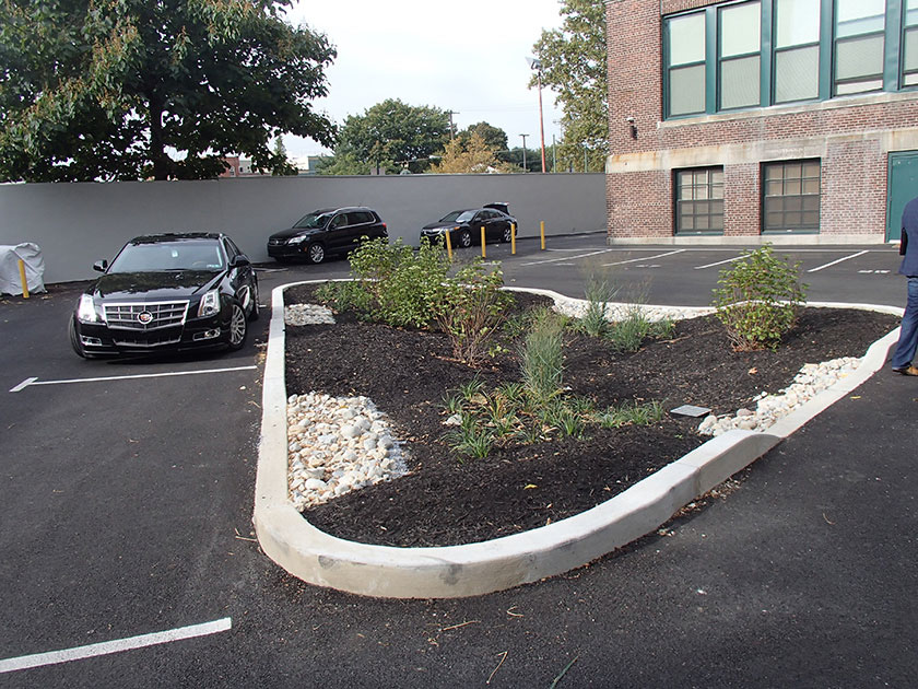
Filter strips consist of densely vegetated land or gravel covered areas, as seen in the photo below, that treats stormwater sheet flow from adjacent pervious and impervious areas. These systems function by reducing runoff velocity, trapping sediment and pollutants, and, in some cases, infiltrating a portion of the runoff into the ground. Filter strips are generally a sensible and cost-effective stormwater pretreatment option applicable to a variety of development sites, including roads and highways.
Design of filter strip SMPs is not limited to the examples shown within this text. Successful stormwater management plans will combine appropriate materials and designs specific to each site.
When can filter strips be used?
Filter strips are a pretreatment option typically applicable to bioinfiltration/bioretention basins and ponds and wet basins. Depending on the site layout and stormwater conveyance design, they may be applicable to subsurface infiltration, subsurface detention, and media filters.
Filter strips are typically used for pretreatment of diffuse sheet flow. They are a pretreatment option for SMPs in residential, commercial, and light industrial developments, and for roads, highways, and parking lots.
Key advantages of filter strips
- Relatively simple structures that provide effective runoff pretreatment
- Effective at slowing runoff velocities, removing pollutant loads, and promoting infiltration of runoff produced by both impervious and pervious areas
- Extend the life of associated SMPs and decrease their hydraulic residence time
- Decrease the frequency of required maintenance of associated SMPs
Key limitations of filter strips
- Require preservation and minimization of impacts leading to compaction and/or erosion
- Often require medium-to-large vegetated areas, making them often impractical in an ultra-urban setting
Key design considerations for filter strips
- Filter strip effectiveness may be enhanced by installing berms and retentive grading perpendicular to the flow path. A pervious berm and/or retentive grading allows for a reduction in both runoff velocity and volume, thus improving pollutant removal capabilities by providing a temporary (very shallow) ponded area.
- The use of existing vegetated areas that have surface features that disperse runoff is encouraged, as the use of these areas will also reduce overall site disturbance and soil compaction.
- Trees and shrubs may be allowed in the flow path if the filter strip exceeds the minimum length and width requirements specified in Table 4.10‑2 below.
- The vegetation for filter strips may be comprised of turf grasses, meadow grasses, shrubs, and native vegetation (Appendix I houses plant lists). Approved native grass mixes are preferable. Seed shall be applied at the rates specified by the supplier.
- Turf grass is generally not recommended but may be acceptable provided the designer can show it meets all requirements.
- A pea gravel diaphragm, which is a gravel-filled trench running along the top of the filter strip’s slope, may be used as a pretreatment level spreader, maintaining sheet flow into the filter strip.
- Vegetation cover should be maintained at 85%. If vegetation is damaged, the damaged areas should be re-established in accordance with the original specifications or according to a new design approved by the Philadelphia Water Department (PWD). In all design cases where vegetation is to be established, the planting regime should be as dense as the soil conditions can sustain. This is especially true at the top portions of the filter strip where the highest sheet flow velocities are found. Soils that can sustain higher quantities and qualities of vegetation may need to be added to ensure the thick vegetative densities needed for sustainable filter strip performance. All vegetation deficiencies should be addressed without the use of fertilizers or pesticides, if possible.
Filter strip design and material standards
- It is critical that plant materials are appropriate for soil, hydrologic, light, and other site conditions. The designer is referred to the list of native species in Appendix I for plant lists. Ponding depth, drain down time, sunlight, salt tolerance, soil infiltration capacities, pollution tolerances, root structure, and other conditions must be taken into consideration when selecting plants.
- Concentrated flow can have an erosive effect that can damage the filter strip, rendering the strip ineffective. If discharge of concentrated flow to the filter strip is proposed, level spreading devices are required to provide uniform sheet flow. The designer is referred to Section 4.12, Outlet Controls, for guidance on level spreaders.
- Filter strips may not be used in high-use areas unless precautions are taken to minimize disturbance of the filter strip, such as signage, fences, and placement of sidewalks or paths to minimize pedestrian or vehicular traffic.
- The maximum allowable flow path to a filter strip, without the installation of energy dissipaters and/or flow spreaders, is 75 feet for impervious ground cover and 150 feet for pervious ground cover.
- The maximum contributing drainage area must be less than five acres and must not exceed a drainage area to filter strip area ratio of 6:1.
- The maximum contributing drainage area slope must be less than 5%, unless energy dissipation and/or flow spreaders are provided up-gradient of the filter strip.
- The filter strip slope must not exceed 8%. Slopes less than 5% are generally preferred. Filter strips with slopes that exceed 5% should implement check dams to encourage ponding and prevent scour and erosion of the filter strip area. The designer is referred to Section 4.10.4, Swales, for additional guidance on check dam design.
- The slope (parallel to the flow path) of the top of the filter strip, after a flow spreading device, must be very small (less than 1%) and gradually increase to the designed value to protect from erosion and undermining of the device.
- Plants must be established at the time of filter strip completion (at least three months after seeding). No runoff must be allowed to flow across the filter strip until the vegetation is established.
- Filter strip length must be in accordance with Table 4.10‑2 below.
Table 4.10‑2: Required starting design values for filter strip length
| Required starting design values for filter strip length | |
|---|---|
| Strip length perpendicular to flow path | Largest feasible on-site |
| Strip length parallel to flow path | Four feet* to 150 feet |
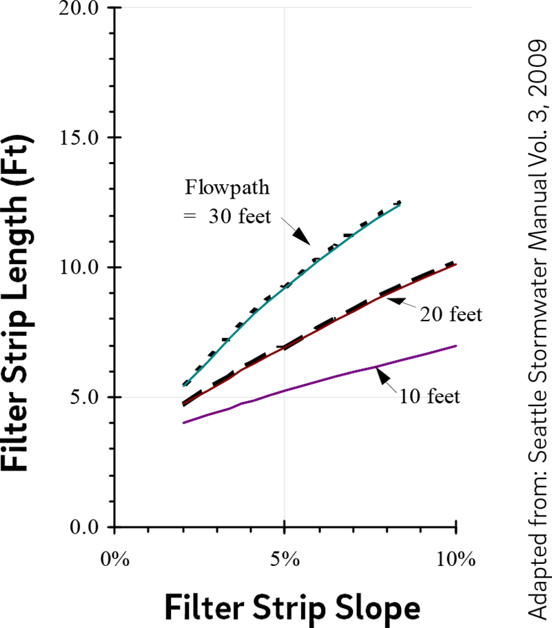
| * The minimum pretreatment filter strip value is based on the length of the receiving flow path. Figure 4.10‑1 below shows how the minimum length requirement changes as both flow path and filter strip slope change. | |
- For contributing flow paths less than 30 feet in length, Figure 4.10‑1 below must be used to determine the filter strip length. The filter strip length requirements reflected in Figure 4.10‑1 are scaled from dimensions of a grassy vegetative swale for the same slope and flow conditions mentioned in Table 4.10‑2.
Figure 4.10‑1: Design specifications for narrow pretreatment filter strips with flow paths less than 30 feet in length
- For contributing flow paths greater than 30 feet in length, the required flow characteristics for maximum velocity and depth listed in Table 4.10‑3 below must be used.
Table 4.10‑3: Maximum velocities and water depths for filter strip area
| Maximum velocities and water depths for filter strip area | |
|---|---|
| Maximum velocity | 1 ft/s max., less than 0.5 ft/s preferred |
| Maximum water depth | 1 inch max., less than 0.5 inch preferred |
| The values for both maximum velocity and water depth were taken from US DOT Stormwater Best Management Practices in an Ultra-Urban Setting: Selection and Monitoring and the Seattle BMP Manual. | |
Filter strip construction guidance
Guidance on typical construction sequencing to ensure proper installation and performance of filter strips is as follows:
- Areas for filter strips must be clearly marked before any site work begins to avoid soil disturbance and compaction during construction.
- In areas where soil is compacted, tilling to depths of 12 to 18 inches is necessary. A minimum of six inches of topsoil must be added into the tilled soil column, and small trees and shrubs with capabilities for deep root penetrations should be introduced to maximize the infiltrative capacity of the soil.
- Provide erosion and sedimentation control protection on the site such that construction runoff is directed away from the proposed filter strip location.
- Complete site elevation and retentive grading, if proposed. Stabilize the soil disturbed within the limit of earth disturbance.
- Install energy dissipaters and flow spreaders if required. The designer is referred to Section 4.12, Outlet Controls, for more detailed construction information.
- Construct filter strip as specified in the design.
- Seed and plant vegetation (plants, shrubs, and trees) as indicated on the plans and specifications.
- Once site vegetation is stabilized, remove erosion and sediment control protection.
Filter strip maintenance guidance
All areas of the filter strip should be inspected after significant storm events for ponding. Corrective measures should be taken when excessive ponding occurs.
General recommended maintenance activities for filter strips are summarized in Table 4.10‑4.
Table 4.10‑4: Filter strip maintenance guidelines
| Early maintenance activity | Frequency |
|---|---|
| Inspect erosion control and flow spreading devices until soil settlement and vegetative establishment of contributing areas has occurred. | Biweekly |
| Water vegetation at the end of each day for two weeks after planting is completed. | Daily for two weeks after installation |
| Water vegetation regularly to ensure successful establishment after planting. | Every four days during periods of four or more days without rain, June through August for the 24 months after installation |
| Inspect vegetation for signs of disease or distress. Treat or replace, as necessary. | Biweekly for the first year after installation |
| Ongoing maintenance activity | Frequency |
|---|---|
| Mow and/or trim vegetation (not applicable to all filter strips). Filter strips that need mowing are to be cut to a height no less than four inches. Greater than five inches is preferred. | As needed |
| Inspect all vegetated strip components expected to receive and/or trap debris and sediment for clogging, excessive debris, and sediment accumulation; remove sediment during dry periods. | Quarterly |
| Inspect vegetated areas for erosion, scour, and unwanted growth. This should be removed with minimum disruption to the planting soil bed and remaining vegetation. | Semiannually |
| Inspect all level spreading devices for trapped sediment and flow spreading abilities. Remove sediment and correct grading and flow channels during dry periods. | Semiannually |
| Maintain records of all inspections and maintenance activity. | Ongoing |
When correcting grading of a flow spreading device, proper erosion and sediment control precautions should be used in the concentrated area of disturbance to ensure protection of the remaining portion of the filter.
Disturbance to filter strips should be minimal during maintenance. At no time should any vehicle be driven on the filter strip. In addition, foot traffic should be kept to a minimum.
If the filter strip is of the type that needs mowing, such as turf grass and possibly other native grasses, push mowers, not riding mowers, should be used. The filter strip should be mowed perpendicular to the flow path (however not exactly the same path every mowing) to prevent any erosion and scour due to channeling of flow in the maintenance depressions.
Filter strips are often used as a convenient area for snow storage. Therefore, filter strip vegetation should be salt-tolerant, and the project’s SMP Maintenance Schedule Forms should include removal of sand build-up at the toes of the filter strip slope. If the filter strip cannot provide pretreatment in the winter due to snow storage or vegetation choice, another pretreatment should be provided.
4.10.3 Forebays
A forebay is a small impoundment designed to dissipate the energy of incoming runoff and allow for initial settling of coarse sediments. They are typically used for pretreatment of runoff prior to discharge into an SMP. Storage created within forebay systems is primarily intended to promote gross pollutant removal prior to introducing flow into a downstream water quality SMP. The forebay is typically isolated from the downstream SMP facility by an earthen, stone, or concrete berm which creates the outer limitations of the forebay.
In some cases, forebays may be constructed as separate structures, but often they are integrated into the design of larger SMPs. Since forebays are typically designed as surface features, surface forebays are the primary focus of this section. Storm drain piping or other conveyance practices may be aligned upstream of a forebay to discharge into one, or several, forebays, as appropriate for the particular site.
Design of forebays is not limited to the examples shown within this text. Successful stormwater management plans will combine appropriate materials and designs specific to each site.
When can forebays be used?
Forebays are a pretreatment option typically implemented with bioinfiltration/bioretention basins and ponds and wet basins. Depending on the site layout and stormwater conveyance design, they may be applicable to subsurface infiltration, subsurface detention, and media filters. Forebays are typically used for pretreatment at points of concentrated stormwater flow.
Key advantages of forebays
- Very effective at removing coarse sediment and debris from small frequent storm events
- Reduce the frequency of maintenance of the associated SMP
- Enhance pollutant removal capabilities of the associated SMP
Key limitations of forebays
- Take up space and expand the footprint of the associated SMP
- Generally ineffective at fine particulate removal
- Increase construction costs and required land area
- Require careful monitoring and removal of accumulated sediment, which can be visible and create aesthetic concerns
Key design considerations for forebays
- A berm placed on the downslope side of a mild slope can be used to create a forebay without additional excavation.
- As an alternative to an earthen basin, an underground structure may serve as a forebay; however, use of fully enclosed structures must allow accessibility for inspection and maintenance.
- Forebay systems can be vegetated or may be lined with hard materials such as rock or concrete. Vegetation within forebays can help to improve aesthetics and assist with pollutant removal; however, high velocities and high rates of sedimentation within forebays can make vegetation survival difficult.
- Forebays should be installed in locations that are accessible by maintenance equipment and should be designed for ease of maintenance. Those constructed with a bottom made of concrete or other solid materials make sediment removal easier and more accessible by heavy machinery.
- Forebay sizing should consider expected level of sediment loading. Drainage area size and characteristics have an impact on the nature and frequency of maintenance activities and corresponding long-term performance. For example, large parking lots deliver more sediment to an SMP than roof areas and therefore require additional maintenance than systems that receive only roof runoff.
- Exposed earthen slopes and the bottom of the forebay should be stabilized using seed mixes appropriate for soils, mowing practices, and exposure to inundation.
- If the forebay is separated from the downstream SMP by an impervious barrier such as a concrete wall or weir, an outlet control structure may be required to drain the forebay. A designed overflow spillway section may be constructed on the top of the berm separating the forebay from the SMP to allow overflow to exit the forebay and enter the downstream SMP at non-erosive velocities.
Forebay design and material standards
- Forebays within large SMPs, such as ponds and wet basins, must contain 10% to 15% of the total permanent pool volume of the larger SMP.
- For forebays within smaller SMPs such as bioinfiltration/bioretention basins, the storage volume should be sized to retain 0.25 inches of runoff of contributing directly connected impervious area (DCIA), with an absolute minimum of 0.1 inch of runoff.
- A stone berm must physically separate the forebay from its associated SMP. The berm should span the entire width of the basin.
- Inlet controls for forebays must include riprap aprons, stone placed in concrete, or some other type of energy dissipation device to rapidly reduce the inflow velocity for erosion/scour protection and to encourage settlement of suspended solids. The designer is referred to Section 4.11, Inlet Controls, for information on design requirements for inlet control systems.
- Permanent vertical markers constructed of durable materials must be installed within the forebay area to indicate the sediment depth.
- Inspection and maintenance access must be provided to allow for periodic sediment removal; this is most commonly provided via stabilized and mildly sloping graded areas that can be accessed by heavy equipment.
- Exit velocities from the forebay must be non-erosive. The designer is referred to the latest edition of the Pennsylvania Department of Environmental Protection (PA DEP) Erosion and Sediment Pollution Control Program Manual for information on design standards for erosion and sedimentation control practices.
Forebay construction guidance
Guidance on typical construction sequencing to ensure proper installation and performance of forebays is as follows:
- Install all temporary erosion and sedimentation controls. The area immediately adjacent to the forebay must be stabilized in accordance with the latest edition of the PA DEP Erosion and Sediment Pollution Control Program Manual prior to SMP construction.
- Prepare site for excavation and/or embankment construction.
- All existing vegetation should remain, if feasible, and must only be removed if necessary for construction.
- If excavation is required, clear the area to be excavated of all vegetation. Remove all tree roots, rocks, and boulders only in excavation area.
- Excavate bottom of forebay to desired elevation (if necessary).
- Install surrounding embankments and inlet and outlet control structures.
- Grade subsoil in bottom of forebay and compact surrounding embankment areas and around inlet and outlet structures.
- Apply and grade planting soil.
- Seed, plant, and mulch according to Planting Plan.
Forebay maintenance guidance
All areas of the forebay should be inspected after significant storm events. Corrective measures must be taken if erosion or excessive debris accumulation occurs. General recommended maintenance activities for forebays are summarized in Table 4.10‑5.
Table 4.10‑5: Forebay maintenance guidelines
| Ongoing maintenance activity | Frequency |
|---|---|
| Remove trash and debris. | As needed |
| Weed by hand and remove invasive plants. | As needed |
| Grassed areas require periodic prudent fertilizing, de-thatching, and soil conditioning. | As needed |
| Trees, shrubs, and other vegetative cover will require periodic maintenance such as fertilizing, pruning, and pest control. | As needed |
| Mow/trim forebay vegetation. | As needed |
| Dredge sediment. Accumulated sediment must not occupy greater than 50% of the forebay volume. | As needed, but at least once every five years* |
| Inspect forebay for potential problems including subsidence, erosion, cracking, or tree growth on the stabilized overflow spillway embankment; damage to the spillway; sediment accumulation; changes in the condition of the inflow; and erosion within the forebay and banks. | Annually |
| Maintain records of all inspections and maintenance activity. | Ongoing |
| * The frequency of sediment removal depends on site conditions such as soil type and maintenance of site stabilization which influence the sediment load on the basin. | |
In most cases, no specific limitations have been placed on disposal of sediments removed from forebays. Studies to date indicate that sediments are likely to meet toxicity limits and can be safely landfilled. It is the owner’s responsibility to ensure that the sediment is not contaminated. On-site sediment disposal is always preferable as long as the sediments are deposited away from the edge of the forebay to prevent their re-entry, and away from recreation areas where people could inhale resulting dust. Information regarding sediment disposal should be provided to the property owner by the design professional.
Sediments should be tested for toxicants in compliance with current disposal requirements if land uses in the drainage area are commercial or industrial, or if indications of pollution are seen or smelled.
4.10.4 Swales
A swale is an open channel vegetated with a combination of grasses and other herbaceous plants, shrubs, and/or trees that can reduce peak flow at the discharge point by increasing travel time and friction along the flow path. A traditional swale typically provides conveyance and pretreatment to another SMP, such as a bioinfiltration/bioretention basin, and provides some infiltration and water quality benefits. Check dams can increase these functions by providing ponding areas where settling and infiltration can occur. As the number of check dams increases, a swale may resemble a series of bioinfiltration/bioretention basins while still being designed to convey peak flows. Swales planted with turf grass provide some of these functions, but turf grass is not as effective as deeper-rooted vegetation at decreasing peak flow rates, allowing infiltration, and controlling erosion. A swale can be more aesthetically pleasing than a concrete or rock-lined drainage system and is generally less expensive to construct. Runoff can enter the swale through a curb opening, pipe, weir, or other design, and it may flow off of a curbless parking lot or road and down a swale slope in a diffuse manner.
When not used for conveyance and/or pretreatment, swales may be considered narrow bioinfiltration/bioretention basins, if designed as such. This section only covers the design of swales as pretreatment systems; the designer is referred to Section 4.1, Bioinfiltration/bioretention, for guidance on swales designed for Water Quality treatment.
Design of swales is not limited to the examples shown within this text. Successful stormwater management plans will combine appropriate materials and designs specific to each site.
When can swales be used?
Swales are pretreatment options typically applicable to bioinfiltration/bioretention basins and ponds and wet basins. Depending on the site layout and stormwater conveyance design, they may be applicable to subsurface infiltration, subsurface detention, and media filters.
Swales are typically used for pretreatment and/or conveyance of concentrated stormwater flow. They may be applicable in many urban settings, including parking lots, commercial and light industrial facilities, and roads and highways (via median strips and shoulders). Swales can also be used in residential developments and constructed, with approved property agreements, parallel to the sidewalks and streets. Alternatively, they can collect stormwater from multiple properties and convey it to a shared SMP.
Key advantages of swales
- Allow for flexible design for both stormwater treatment and conveyance
- Can often be used in lieu of more expensive subsurface conveyance or rock-lined/concrete channels
- Can effectively balance storage, treatment, and infiltration with peak flow conveyance needs
- Can be designed to fit into many types of landscapes in an aesthetically pleasing manner
- Can effectively balance needs for infiltration and treatment during small storms with needs for conveyance during large storms
Key limitations of swales
- Generally distributed across a larger area than other SMPs
- May have limited opportunities for implementation due to the amount of open space available at the site
Key design considerations for swales
- The first ponding area may be designed as a sediment forebay and function as a pretreatment practice for the remainder of the swale or downstream SMPs. Vegetated or stone filter strips are also options for pretreatment.
- The excavated channel itself provides the storage volume and conveyance capacity of the swale. An effective swale design will balance the need for infiltration and treatment during small storms with need for conveyance during large storms.
- The site’s natural topography should be considered when siting the swale; if possible, the swale should be located along contours and natural drainage pathways with slopes of 2% to 3%.
- A bottom channel width of two to eight feet is recommended.
- The soil provides a growing medium for plants and allows for infiltration. The growing medium may consist of amended in situ soils or imported soil.
- A crushed stone layer may be added beneath the soil to increase storage and promote infiltration. Stone will perform this function most effectively when placed beneath ponded areas.
- In some cases, an underdrain and piping system may be designed to prevent prolonged ponding of stormwater or to collect and convey water to another facility such as an infiltration trench. Underdrain systems may be appropriate in locations where conditions are not ideal for infiltration. The designer is referred to Section 3.3 for detail on minimum infiltration rates and infiltration testing requirements.
- Vegetation or ground cover within a swale should be suitable for expected velocities. For the swale flow path, native grass mixes are preferable. Native wildflowers, grasses, and ground covers, which can be designed to require mowing only once or twice annually, are preferred to turf and lawn areas.
- It is recommended that swale SMP designs include check dams. Ponding behind check dams provides storage, increases infiltration, increases travel time, reduces peak flows, and helps prevent erosion by dissipating energy.
- Check dams can be constructed from concrete, stone, boulders, earth, or other materials.
- If a stone check dam is designed to be overtopped, appropriate selection of aggregate will ensure stability during flooding events. In general, one stone size for a dam is recommended for ease of construction. However, two or more stone sizes may be used, provided a larger stone (e.g., R-4) is placed on the downstream side, since flows are concentrated at the exit channel of the weir. Several feet of smaller stone (e.g., American Association of State Highway and Transportation Officials #57) can then be placed on the upstream side. Smaller stone may also be more appropriate at the base of the dam for constructability purposes.
- Check dams should be evenly spaced and at least six inches high.
Swale design and material standards
- If a swale is being designed as a primary SMP, it must meet the applicable design requirements for bioinfiltration/bioretention basins, as well as the applicable requirements in this section. The designer is referred to Section 4.1, Bioinfiltration/bioretention, for guidance and design requirements.
- Swales must convey the ten‑year, 24‑hour storm with a minimum of six inches of freeboard and a maximum depth of 18 inches. Flow over check dams may be estimated using a weir equation.
- Swales must be designed to resist erosion. It is recommended that the swale convey the two‑year, 24‑hour storm without erosion. The latest edition of the PA DEP Erosion and Sediment Pollution Control Program Manual is recommended as a reference for these calculations. Soil mix, vegetation, and temporary or permanent stabilization measures must be adjusted as needed.
- Plants must be established at the time of swale completion (at least three months after seeding).
- Energy dissipaters must be evaluated for use at points of concentrated inflow. The designer is referred to Section 4.11, Inlet Controls, for information on the design of energy dissipaters.
- It is critical that plant materials are appropriate for soil, hydrologic, light, and other site conditions. The designer is referred to the list of native species in Appendix I for plant lists. Ponding depth, drain down time, sunlight, salt tolerance, and other conditions must be taken into consideration when selecting plants. Turf grass is generally not recommended but may be acceptable provided the designer can show it meets all requirements.
- Maximum side slopes for parabolic channel swales are as follows:
- All – 2(H):1(V) (The recommended side slope is 3(H):1(V))
- Mowed – 4(H):1(V) to avoid “scalping” by mower blades
- Check dams intended to provide ponding in swale SMP designs must not be porous (i.e. composed of stone gabions), as water should be ponded behind each check dam and forced to infiltrate. If the swales are only being used for conveyance or to increase time of concentration, check dams may be porous.
Swale construction guidance
Guidance on typical construction sequencing to ensure proper installation and performance of swales is as follows:
- To promote infiltration through swales, rock construction entrances must not be located on top of areas of proposed swale bottoms.
- Heavy equipment exclusion zones must be established to avoid compaction of the swale’s bottom footprint during construction.
- Begin vegetated swale construction only when the up-gradient site has been sufficiently stabilized and temporary erosion and sediment control measures are in place. Vegetated swales should be constructed and stabilized very early in the construction schedule, preferably before mass earthwork and paving increase the rate and volume of runoff. The designer is referred to the latest edition of the PA DEP Erosion and Sediment Pollution Control Program Manual for information on design standards for erosion and sedimentation control practices.
- Rough grade the swale. Equipment must avoid excessive compaction and/or land disturbance. Excavating equipment should operate from the side of the swale and never on the bottom. If excavation leads to substantial compaction of the subgrade (where an infiltration trench is not proposed), 18 inches must be removed and replaced with a blend of topsoil and sand to promote infiltration and biological growth. At the very least, topsoil must be rototilled into the subgrade in order to penetrate the compacted zone and promote aeration and the formation of macropores. Following this, the area should be disked prior to final grading of topsoil.
- Construct check dams, if required.
- Fine grade the swale. Accurate grading is crucial for swales. Even the smallest non-conformities may compromise flow conditions.
- Seed and vegetate according to final planting plans. Seeding with an annual turf grass is recommended to provide temporary stabilization. Plant the swale at a time of the year when successful establishment without irrigation is most likely. Provide temporary irrigation during any periods of little rain or drought. Vegetation should be established as soon as possible to prevent erosion and scour.
- Concurrent with the previous step, stabilize freshly seeded swales with appropriate temporary or permanent soil stabilization methods, such as erosion control matting or blankets. If runoff velocities are high, consider sodding the swale or diverting runoff until vegetation is fully established. Erosion and sediment control methods must adhere to latest edition of the PA DEP Erosion and Sediment Pollution Control Program Manual.
- Once the swale is sufficiently stabilized, remove temporary erosion and sediment controls. It is very important that the swale be stabilized before receiving stormwater flow. No runoff must be allowed to flow in the swale until grass is established.
Swale maintenance guidance
Swales should be inspected after significant storm events, and corrective measures should be taken if erosion or excessive debris accumulation occurs. General recommended maintenance activities for swales are summarized in Table 4.10‑6.
Table 4.10‑6: Swale maintenance guidelines
| Ongoing activity | Frequency |
|---|---|
| Treat or replace diseased trees and shrubs. | As needed |
| Inspect soil and repair eroded areas. | Monthly |
| Remove litter and debris. | Monthly |
| Clear leaves and debris from overflow. | Monthly |
| Replace filter bags for pretreatment devices. Ensure filter bag is installed properly. | Quarterly |
| Inspect trees and shrubs to evaluate health. | Semiannually |
| Prune trees and shrubs. | Annually |
| Inspect for sediment build-up, erosion, vegetative conditions, etc. | Annually |
| Inspect outlet control devices after several storms to ensure that they are functioning properly and that there are no erosion problems developing. | Ongoing |
| Maintain records of all inspections and maintenance activity. | Ongoing |