This section will guide the designer in performing a site assessment—the necessary first step in designing a project that complies with the Philadelphia Water Department (PWD) Stormwater Regulations (Stormwater Regulations), or a grant-funded Stormwater Retrofit project. The designer must know the site location and general development plan before beginning the site assessment process.
The assessment consists of two components: the investigation of background site factors, and an analysis of how these factors will shape the development and stormwater management plan for a proposed site. Site assessment must be completed in the early stages of project design, and information gained from the assessment will be requested as part of the Existing Resources and Site Analysis (ERSA) Application Submission Package (Section 2.1.1) to PWD. Stormwater Grant-funded Stormwater Retrofits should include site assessment details within the Stormwater Grant Application materials and submitted Conceptual Stormwater Management Plan.
A properly completed site assessment helps the designer understand a site’s existing condition and natural systems. The assessment aids the designer in determining the most appropriate site layout and crafting a stormwater management approach and design for a site.
3.1.1 Background site factors and site factors inventory
Macro site factors consist of watershed-scale project site characteristics. These factors include a project’s watershed and sewershed, and factors that influence flooding.
Micro site factors are smaller, site-scale features including property/land use boundaries and physical features that may affect the site layout or stormwater compliance strategy, for example, the presence of previously installed stormwater management practices (SMPs) on the project property and adjacent properties. If this is a concern, the designer should refer to PWD’s Big Green Map, which inventories both public and private stormwater management infrastructure. Both macro and micro factors will play a significant role in determining not only the applicable Stormwater Regulations but also the best strategies for complying.
Project watershed
A watershed is an area of land that contains a common set of drainage pathways, streams, and rivers that all discharge to a single, larger body of water, such as a large river, lake, or ocean. There are seven major watersheds in Philadelphia. Watershed Maps in Appendix D are available to assist the designer in determining a site’s watershed.
While Water Quality requirements are generally consistent across all of Philadelphia’s watersheds, they do differ in terms of rate control requirements: specifically, Flood Control and Channel Protection. This is because the frequency and magnitude of flooding in headwater streams is affected to a far greater degree by unmanaged stormwater than in larger receiving bodies of water such as the Schuylkill or Delaware Rivers. There are some watersheds which are especially impaired in terms of water quality, localized flooding, and stream bank erosion that necessitate the compliance of small earth disturbance projects with some or all aspects of the Stormwater Regulations (Section 1.2.1).
Project sewershed
A sewershed is a defined area of land, or catchment, which drains via storm drain infrastructure to a common outlet point. As opposed to natural watersheds, the boundaries of which are defined by natural ridges, sewershed boundaries are determined by stormwater infrastructure such as curbs, storm drains, pipes, and stream outfalls. Sewershed boundaries may differ from watershed boundaries because stormwater infrastructure may cross watershed boundaries that predate urbanization.
Runoff may leave a site through a combined sewer system, separate sewer system (PWD-owned or private outfall), or via surface runoff. Some project sites may span multiple sewersheds, and runoff may leave different portions of the site via different methods. Discharge to different sewersheds will not only affect the stormwater management strategy, but also the requirements associated with the Water Quality requirement for the site, as these are different in combined sewer areas than other sewersheds. In addition, projects that discharge to a combined sewer system may be subject to a Public Health and Safety (PHS) Release Rate requirement because of specific capacity limitations in the combined sewer system. The designer is referred to Appendix D for a map of PHS Release Rate areas and their associated rates. Rates can also be found in the Reg Finder.
Projects that can discharge stormwater runoff without the use of PWD infrastructure may qualify for exemption from some rate control requirements (Section 1.2.1); however, they may have additional permitting requirements from the Pennsylvania Department of Environmental Protection (PA DEP) (Section 2.7) and may require the creation of easements if stormwater runoff will be directed to neighboring property via piped or diffused discharge.
Appendix D contains Collection System Maps for use in determining the project sewershed. However, applicants with projects that are located near a sewershed boundary may want to contact PWD to confirm.
Flooding
An evaluation of existing flooding issues on a project site, or on adjacent properties, must be performed. For example, it is important to know whether floodwaters flow via an overland flow path on the site, and whether runoff from off-site properties is a component of these flows. It is also crucial to understand how flooding impacts the conveyance capacity of storm sewer infrastructure if the design proposes overflow connections from SMPs. This is especially important for private or semi-private systems. For example, there may be a high tailwater condition at the outfall or connection point during a relatively small rainfall event. The designer must account for these conditions during SMP design.
Although Federal Emergency Management Agency (FEMA) flood maps and related studies show flood-prone areas along the City’s streams and rivers, these resources do not adequately address this issue at site scale. Prior property owners, neighbors, and other local sources may be able to indicate anecdotally the extent to which on-site or downstream flooding is already a problem. A review of historic maps may also provide an indication of possible flooding issues, specifically if the site is located in the vicinity of a historic stream or creek that was infilled or bricked up as a combined sewer.
Published FEMA Flood Maps are available at the Philadelphia City Planning Commission, which can be reached by phone at (215) 683‑4615, or online at FEMA’s Flood Map Service Center.
Property/land use boundaries
Property/land use boundaries refer to the parcel’s non-physical boundaries, such as zoning classification and/or overlays, setbacks, and any existing easements. Suitable locations for SMPs must be identified by mapping existing property/land use features. These features often leave large spaces of undevelopable land available for non-structural design opportunities and/or structural SMPs. Boundaries must be depicted on the Existing Conditions Plan submitted during the Conceptual Review Phase. The designer is referred to Section 2.1.1 and Appendix E, Table E‑2 for specific Existing Conditions Plan requirements.
Physical features
It is necessary to assess important physical features within the project site to minimize impacts to these features and to identify opportunities to use existing natural areas and drainage patterns for stormwater management. Table 3.1‑1 lists critical physical features that are required to be inventoried and understood, the methods and data sources for assessing these features, and whether each feature is required for an Existing Conditions Plan. Care must be taken to conserve and protect, or avoid, these areas, as appropriate.
Table 3.1‑1: Physical site features required in Existing Conditions Plan
| Physical Feature | Action | Source |
|---|---|---|
| Vegetation | Determine the location and extent of woodlands, riparian areas, or other special habitat areas (e.g., meadows) as defined by the Pennsylvania Stormwater Best Management Practices (BMP) Manual (2006 or latest version). | Topographic survey, aerial photography, Geographic Information Systems (GIS) mapping, local and regional natural resources inventories, Pennsylvania Natural Diversity Inventory (PNDI) surveys |
| Soils and geology | Determine existing soil conditions, expected permeability, hydrologic soil groups, depths to high seasonal groundwater table/bedrock, and presence of hydric soils or special geologic formations (e.g., carbonate). Document whether the site has native soils or if past development has led to fill conditions. | United States Department of Agriculture (USDA) Soil Surveys, hydrologic soil maps, existing geotechnical reports, existing soil investigation or infiltration reports, United States Geological Survey (USGS) Quadrangle Maps, USGS historic fill maps, historical aerial photography, local or regional groundwater studies or well data (Note: Usefulness of soil survey data for soils in urban settings may be limited) |
| Wetlands, waterways, floodplains, and drainageways | Note location and type of on-site waterbodies, waterways, and floodplains. Determine existing drainage pathways and patterns, both on-site and for site runoff to off-site receiving waters. | Topographic survey, FEMA Flood Maps, aerial photography, GIS mapping |
| Existing structures and paved areas | Determine on-site location of buildings, sheds, loading docks, parking lots, driveways, sidewalks, trails, etc. | Topographic survey, aerial photography |
| Existing stormwater infrastructure | Determine on-site locations of stormwater pipes, manholes, inlets, catch basins, outfalls, etc. | Topographic survey, utility records |
| Existing utilities, sewer, and water lines (within 25 feet of property lines) | Determine on-site locations of sewer pipes, manholes, force mains, water lines, water manholes, valve box covers, gas service lines, gas transmission mains, electric lines, and telephone/ cable/ fiber optic lines. | Topographic survey, utility records, utility locator services (PA One Call, private contractors) |
| Steep slopes | Determine location of slopes of 15% or greater. Determine whether site is located in Steep Slope Protection Area, as per Philadelphia Code §14‑704(2). | Topographic survey, GIS topographic data, Philadelphia Code |
Hotspot investigation and historic fill assessment
Understanding the presence, extent, and location of potential soil, groundwater, or surface water contamination and potentially unstable fill is an important component of characterizing existing site conditions. Infiltration of stormwater through contaminated soils has the potential to negatively impact groundwater and downstream surface water bodies. Additionally, concentrated infiltration of stormwater in areas of unstable fill can increase the potential for soil stability issues such as differential settlement and sinkhole formation. The presence of both contamination and unstable fill can present significant risks to public health and public safety and can damage public and private property.
During this phase of the site assessment, the designer collects important information on both of these factors that may ultimately inform the placement of SMPs as described in Section 3.2 and whether SMPs can be designed as infiltrating facilities or must instead be designed as slow-release facilities. If a project can comply with the Stormwater Regulations solely through non-structural design techniques and/or disconnected impervious cover (DIC) (Sections 3.1.4 and 3.1.5, respectively), a hotspot and historic fill assessment may not be needed for stormwater management purposes.
The designer should use the following hotspot investigation and historic fill assessment procedure to identify soil contamination and unstable fill risks and to evaluate the potential for implementing infiltration SMPs if these conditions are present.
Step 1
Determine the prior land use at the site where development is proposed, and review all available data on soil and groundwater quality.
This can be done through a formal Phase I site assessment or informally by conducting a title search; a review of aerial photographs, soil surveys, topographic maps, City and State regulatory databases; and a review of local and State records. Historic maps, records of previous construction, local knowledge, or test pit data can also be used to determine whether contamination is present on-site, if the site has a history of hotspots, or the presence of unstable fill.
Step 2
Determine the potential for groundwater or surface water contamination through infiltrating SMPs based on available data and prior land use (determined in Step 1), history of hotspots, and suspected/known presence of unstable fill.
The following land uses are considered to have a potential for contaminated soil, which may adversely affect the quality of groundwater discharging to surface water. These uses may qualify a project site, or portions of it, as a hotspot.
- Sites designated as Comprehensive Environmental Response, Compensation, and Liability Act (CERCLA) sites, also known as Superfund Sites,
- Sites registered under PA DEP’s Land Recycling Program, or Act 2 sites (Section 2.7.2),
- Auto recycling facilities and junkyards,
- Commercial laundry and dry-cleaning facilities,
- Commercial nurseries,
- Vehicle fueling stations, service and maintenance areas,
- Toxic chemical manufacturing and storage facilities,
- Petroleum storage and refining facilities,
- Public works storage areas,
- Airports and deicing facilities,
- Railroads and rail yards,
- Marinas and ports,
- Heavy manufacturing and power generation facilities,
- Landfills and hazardous waste material disposal facilities, and
- Sites located on subsurface material such as fly ash known to contain mobile heavy metals and toxins.
Infiltration is required on all sites unless the designer can show that it is not feasible. A common factor in the preclusion of infiltration is the potential for contaminant migration (Step 3). Hotspot usage and historic fill sites could contain fill material, such as fly ash, which may contain mobile metals and toxins, as well as being a potentially unstable soil. When concentrated infiltration is present within regions with known hotspot usage or fly ash fill, infiltration can lead to extensive erosion and subsidence of infill containing very fine material. The designer is responsible for investigating the presence of contaminated or unstable soils.
If Steps 1 and 2 reveal that the presence of hotspots or unstable fill is known or anticipated, the designer must proceed to the detailed testing procedures in Step 3. Before starting Step 3, the designer is encouraged to identify initial areas that could be used for stormwater management so that testing can be focused on potential SMP areas.
Step 3 (if necessary)
Conduct field investigations to further evaluate contamination and/or historic fill.
For project sites that qualify as hotspots, due diligence must be performed to determine whether any contamination is present on-site. It is insufficient to rule out infiltration based on historical site uses alone. Testing must be performed to determine whether the site is contaminated and, if so, the areas where contamination is concentrated. Even if a site is contaminated, there may be some areas where infiltration is still feasible. Contamination must be evaluated per PA DEP guidelines, including, but not limited to, comparing testing results to PA DEP Direct Contact Medium Specific Concentration (MSC) thresholds and Soil-to-Groundwater MSC thresholds, evaluating contaminant solubility, and conducting Synthetic Precipitation Leachate Procedure (SPLP, EPA Method SW-846-1312) testing.
For project sites that anticipate the presence of unstable fill, the designer must work with a geotechnical professional to create an action to identify if unstable fill exists and whether the fill is suitable for infiltration. Field testing may include, though is not limited to, soil sampling, the use of ground penetrating radar (GPR), and electromagnetic induction (EMI) scanning.
Many sites in Philadelphia are constructed on fill; however, the presence of fill alone does not preclude a site from installing infiltrating practices. A waiver from the infiltration requirement can be requested if sufficient proof of soil instability or soil contamination is provided based on soil sampling results (Section 3.3.6). To request a waiver from infiltration due to contamination, the designer or applicant must submit environmental reports for any testing completed, as well as a justification letter from the geotechnical engineer or environmental professional clearly stating why infiltration is not recommended. If appropriate justification and documentation is provided to demonstrate that contamination or soil stability precludes the site from infiltrating, an impervious liner may be necessary for SMPs where stormwater is concentrated.
3.1.2 Site factors analysis
The final step in the site assessment is to review the information obtained from the background and site factors inventories and perform a stormwater management opportunities and constraints analysis. This analysis will identify areas where stormwater management may or may not be appropriate and assist the designer in making preliminary determinations regarding the size and layout of any development features.
Stormwater management opportunities
The designer must identify site characteristics that are favorable to stormwater management, such as soils with desirable permeability or locations for proposed discharge points (e.g., connections to existing storm sewers). Likewise, site development should be focused as much as possible in areas that provide poor opportunities for stormwater management, maximizing the areas conducive to stormwater. Certain types of critical natural areas can present both constraints to land development and significant opportunities for stormwater management. For example, riparian areas, which are not prime development areas, can sometimes be used to disconnect impervious cover (Section 3.1.5). However, the environmental impacts of implementing stormwater management in natural areas must be carefully considered.
Recognizing opportunities during site assessment to reduce the proposed directly connected impervious area (DCIA) to manage—while also protecting and using existing site features—can lower the costs associated with projects meeting the Stormwater Regulations or pursuing Stormwater Retrofits. Additionally, proposed site features that are conducive to stormwater management should be identified. For instance, areas such as parking lot islands can be used for surface management of stormwater. The designer is referred to Section 3.2 for additional guidance on stormwater management design strategies and to Section 3.5 for examples of integrated stormwater management strategies for different project types.
Stormwater management constraints
Stormwater management constraints are areas on the project site where stormwater management may be difficult, infeasible, or inadvisable. These can include constraints such as contamination, existing utilities, wetlands, riparian buffers, steep slopes, and soils with high permeability. The designer is referred to Section 3.2 for a discussion of constraints related to specific design strategies and to Chapter 4 for constraints related to different SMP types.
For those development projects where all impervious areas within the limit of disturbance cannot be disconnected, and with constraints that prohibit stormwater management of the remaining DCIA on-site, the applicant should investigate opportunities to provide off-site management as described in Section 3.2.4 (Stormwater Management Banking and Trading). If no such opportunities exist, the applicant may consider making a one-time fee-in-lieu payment for the unmanaged DCIA. All requests for fee-in-lieu payment must be approved by PWD. More information on the criteria for fee-in-lieu is provided in Section 3.4.1.
3.1.3 Integrated design approach
PWD has created an integrated design approach through which developers can meet the Stormwater Regulations for proposed development projects. The intent of the approach is to promote the use of stormwater management solutions that protect receiving waters in a cost-effective manner. The integrated design approach presented here is based on recommendations found within the PA DEP Pennsylvania Stormwater Best Management Practice (BMP) Manual, with minor modifications for adaptation to Philadelphia’s urban conditions. For example, non-structural design, one of three major design strategies discussed in this section, may be challenging to implement in cases where higher densities/intensities are proposed on small sites in densely developed areas. However, non-structural DIC opportunities may be more cost-effective in the highly dense areas of Philadelphia because of energy savings, retail value, and other factors. Additional informational resources on the economic benefits of incorporating green features into an urban environment can be found on the PWD Stormwater webpage.
The process of integrating site development and stormwater management design begins with a comprehensive understanding of existing site conditions facilitated by a site assessment, as described in Section 3.1.1 and Section 3.1.2. The site assessment process allows the designer to identify key site and stormwater management design opportunities and constraints. For example, the designer may desire to locate a proposed building to preserve an existing large and mature tree or an area of existing native vegetation in good condition in order to obtain credits for preserving existing trees under Philadelphia Code §14‑705(g). In addition, low-lying areas on a site can be used for SMPs in order to minimize conveyance costs.
With an integrated design approach, the designer uses a combination of three primary strategies to meet the Stormwater Regulations, as applicable: non-structural design, non-structural DIC (rooftop, pavement, and/or tree disconnections), and structural SMPs (e.g. bioinfiltration/bioretention basins, porous surfaces, and green roofs). These strategies are implemented initially in sequence, then in an iterative approach, leading to formulation of a comprehensive site and stormwater management design as illustrated in Figure 3.1‑1.
Figure 3.1‑1: PWD’s integrated design approach
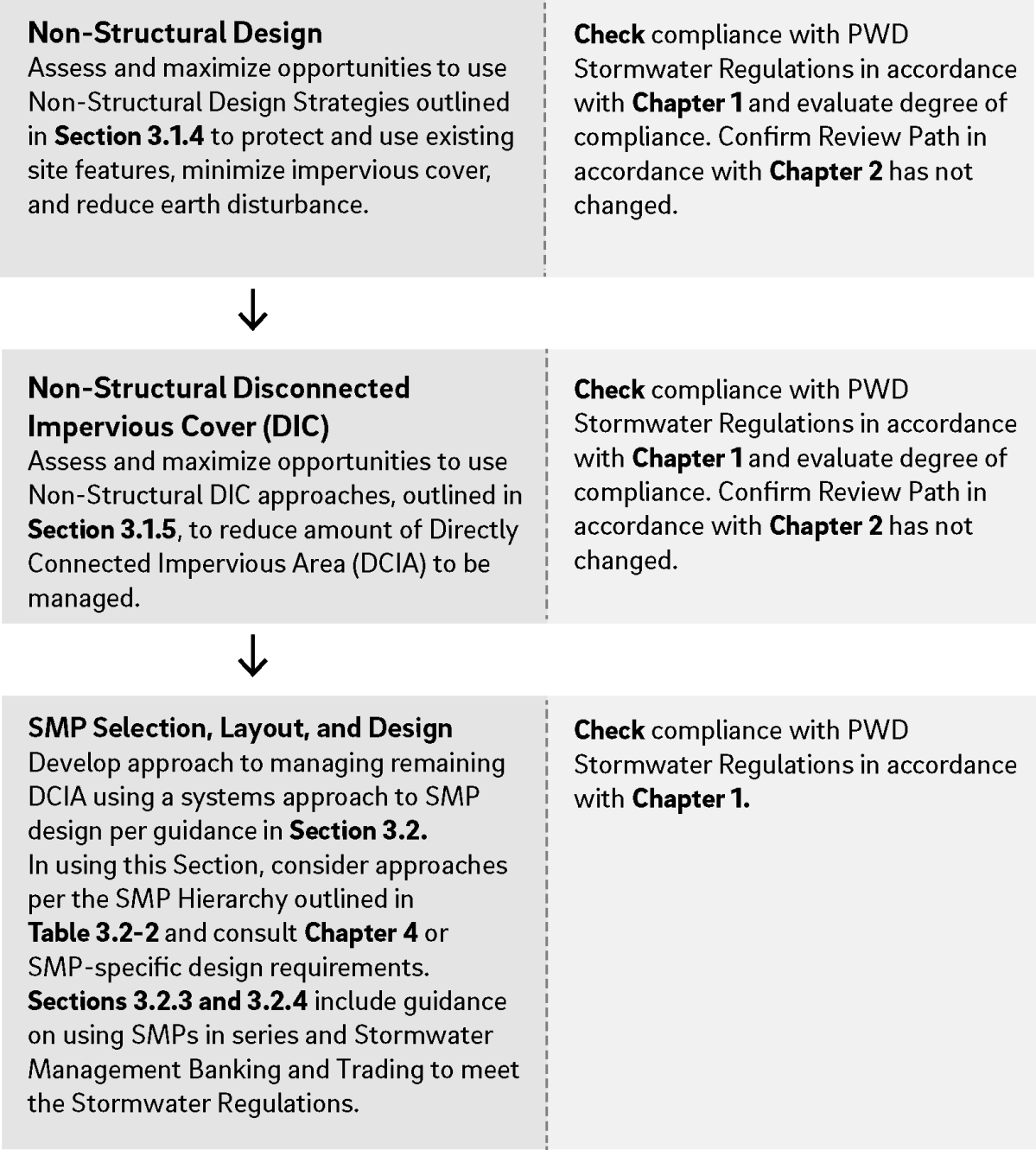
3.1.4 Non-structural design
PWD places a premium on protecting sensitive and special value resources and preserving the natural systems and hydrologic functions that may be present on a site. Non-structural strategies, a primary characteristic of low-impact development, promote the treatment, infiltration, evaporation, and transpiration of precipitation close to where it falls, and are the primary means by which the designer works to preserve and protect high-value natural features. PWD recommends that the designer use non-structural design practices early in the site planning process to reduce the size and cost of stormwater management facilities. Implementing these practices involve the careful consideration of the project site’s predevelopment condition, topography, natural drainage systems, and landscaping to arrange site development features in ways that minimize the use of impervious cover and the disruption of existing natural features, while promoting the use of construction staging strategies that limit disturbance and soil compaction.
When used in combination, non-structural strategies can result in a variety of environmental and financial benefits. In the designer’s interest, the use of non-structural design practices can reduce land clearing and grading costs, reduce the size and cost of stormwater management facilities, reduce the cost and scope of operations and maintenance, and increase property values. In some cases, these strategies can result in the preservation of open space and working lands; the protection of natural systems; and the incorporation of existing site features, such as wetlands and stream corridors, which provide natural hydrologic and water quality functions in addition to fish and wildlife habitat.
Non-structural strategies
While most development sites within Philadelphia do not generally possess extensive natural systems, more modest natural systems and features may possess sufficient value to warrant preservation and integration within the development plan. These features may include mature trees or flowering shrubs, natural topography or rock outcroppings, or plant communities that protect slopes from erosion or act as buffers for streams or drainage ways. The designer must complete a site assessment, as described in Section 3.1.1 and Section 3.1.2, to better understand the property’s existing physical features before exploring non-structural design strategies.
Following the completion of the site assessment, the first step in the stormwater design process is to thoroughly consider the use of non-structural strategies, finding creative ways of incorporating built features around existing natural areas. Recommended non-structural strategies fall within three categories: protecting sensitive and special value resources, clustering and concentrating, and minimizing disturbance and maintenance.
Protect sensitive and special value resources
To minimize stormwater impacts, land development activities should avoid encroaching on areas that provide important natural stormwater functions, such as floodplains, wetlands, and riparian areas, and on areas that are especially sensitive to stormwater impacts, like steep slopes. These features may not be widespread in the urban environment, but where they do exist, they must be identified and protected. By protecting sensitive and special value resources, the designer can make existing natural features an important and integral part of a development site, enhancing the development’s role in the landscape and resilience of the community and providing attractive amenities for future tenants or owners. Protecting these features can also reduce the amount of stormwater runoff discharged from the site. For development in the floodplain, in addition to the requirements from the City of Philadelphia Department of Licenses and Inspections (L&I), special consideration should be given to SMP placement and design to minimize impacts from current and future floodwater inundation.
Within Philadelphia, most development sites do not have extensive sensitive and special value resources due to the density and history of development in the region. Many of the features that provided hydrologic functions within the landscape have been removed, covered, or buried, and most native soils have been removed, compacted, contaminated, or replaced with low-value fill material and debris. For these reasons, it may be difficult to identify substantial resources or features for protection. This relative scarcity of existing resources, however, prompts PWD to recognize the value and function of less extensive natural areas, even to the extent of valuing an individual tree. PWD urges the designer to consider the preservation and enhancement of natural features present at any scale, as well as enhancements that may help to protect natural features adjacent to the site, such as creating buffer zones or stabilizing steep slopes.
When development sites are adjacent to streams or rivers, riparian buffer systems can protect and enhance streams by limiting erosion, filtering and sequestering pollutants, and providing habitat for wildlife. Riparian buffer systems also aid in the prevention of localized flooding and thereby can protect surrounding property from damage by naturally absorbing flood waters, an important process that will be crucial as extreme storms increase with climate change. Buffers can be especially important along steep banks that are vulnerable to erosion and serve to separate waterbodies from decorative landscape areas where fertilizers are applied, and runoff carries nutrients to the open water. Streambeds—the disturbance of which is regulated by State and Federal regulations—support a variety of life and must be protected from trampling or other abuse. In urban areas where riparian habitat is limited, protecting and enhancing remaining streamside corridors is critical to avoiding further impacts to water quality and ecological health.
Special value features
Trees and shrubs are highly effective at retaining precipitation through interception, and all plants further reduce runoff through evapotranspiration. Well-developed root systems help keep soil ecosystems healthy, enhance infiltration, and limit erosion. Naturally-occurring bioretention areas—small, sometimes saturated areas that sustain plant communities such as pocket wetlands and vernal pools—are effective filters that sequester contaminants and support microbes that decompose organic pollutants. These existing vegetated features should be strongly prioritized for preservation. On larger sites, existing drainage pathways, such as natural draws or swales, should be identified and used whenever possible to convey stormwater in the post-development condition. By identifying these features and integrating their preservation within the development plan, sites can benefit from improved quality and reduced volume of off-site stormwater discharges, while simultaneously providing the many benefits of natural vegetation including wildlife habitat, improved air quality, and reductions in the urban heat island effect.
Riparian areas
When development sites are adjacent to streams or rivers, riparian buffer systems can protect and enhance streams by limiting erosion, filtering and sequestering pollutants, and providing habitat for wildlife. Buffers can be especially important along steep banks that are vulnerable to erosion and serve to separate waterbodies from decorative landscape areas where fertilizers are applied, and runoff carries nutrients to the open water. Streambeds—the disturbance of which is regulated by State and Federal regulations—support a variety of life and must be protected from trampling or other abuse. In urban areas where riparian habitat is limited, protecting and enhancing remaining streamside corridors is critical to avoiding further impacts to water quality and ecological health.
Natural flow pathways
Where natural flow pathways or depressions exist, the designer should consider using these systems to help manage site runoff. Planting or protecting existing, deep-rooted plant cover within these existing features can limit erosion. Most larger sites, unless highly disturbed, will possess natural drainage features that, when conditions allow, will sustain and support a diverse plant community while also slowing and filtering runoff before it reaches larger bodies of water. These flow pathways can be attractively integrated within the site’s landscaping, reducing irrigation demands and providing valuable site amenities that require minimal maintenance. Plant choices should be selected from native species that are adapted to the hydrologic conditions expected within the channel. The designer should assess whether existing drainage features are regulated by State or Federal statutes prior to conducting planting within these areas.
Cluster and concentrate
When assessing the programming needs of the development, the designer should attempt to cluster and concentrate structures in order to build on the smallest area possible and minimize extensive DCIA, reserving as much area as possible for “green” cover. By limiting the footprints of buildings, parking areas, and other DCIA, either through stacking or clustering structures on the site, the designer can leave larger areas open for green space programming without reducing gross density. This practice not only improves the ability of the site to manage stormwater but also increases the opportunity for green amenities and enhances long-term property values. Multi-story buildings also have lower energy consumption per square foot of floor space, fetch higher rent compared with low-rise buildings, and retain the urban character of the city.
This practice is not highly applicable to small or single parcel developments but is more conducive to larger master planning for neighborhoods, campuses for hospitals or educational institutions, or redevelopment of large brownfield sites. In these environments, designation of open spaces can provide enhanced access to shared amenities and promote community cohesion. Concentrating buildings can also reduce per unit construction costs and the cost of providing infrastructure and site circulation.
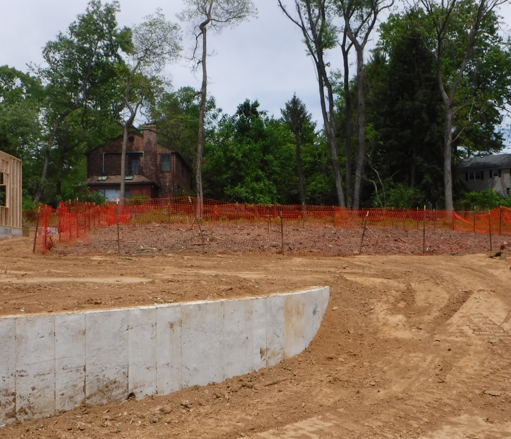
Minimize disturbance and maintenance
Builders and contractors must minimize unnecessary land disturbance in order to limit the movement and compaction of in situ soils and preserve existing vegetation. When planning and staging construction, the designer should work with contractors to avoid trampling or stockpiling where unnecessary, and to stay clear of special value and environmentally sensitive areas. Disturbed or compacted soils are less effective in supporting plant growth and promoting infiltration. Heavy equipment paths must be well marked to avoid unnecessary compaction of in situ soils in areas specified for open spaces, especially areas where infiltration is intended, and tree guards must be erected to prevent damage from construction vehicles. Site planners should also seek to conform to the existing topography to the greatest extent possible, limiting the cost of grading and planting, reducing soil compaction, and assuring that healthy topsoil remains on the surface. These practices will provide for more robust plant growth, speed the recovery of green spaces following construction, and require less maintenance in the long term.
Disturbed areas must be restored with native and recommended adapted non-invasive plants that do not require chemical maintenance and are selected for the appropriate hydrologic regime. In some cases, it will be necessary to protect re-vegetated areas during the establishment period by erecting fences and limiting access.
Other considerations beyond Stormwater Regulations
Beyond the PWD Stormwater Regulations, applicants may want to consider other factors in the stormwater management design to meet both immediate development and the site’s long-term needs. This may include designing the site to comply with both the Stormwater Regulations and Stormwater quantity and/or quality control requirements for LEED certification. Eligible projects may also choose to take advantage of various stormwater management-based Zoning Bonuses to increase a building’s height (Philadelphia Code § 14‑702(14)) and/or density. If there are large swaths of existing impervious area that will not be disturbed during construction the applicant may want to consider capturing these areas as well to maximize potential stormwater credits (Section 6.3).
How to use non-structural strategies to help comply with the Stormwater Regulations
The designer can use non-structural strategies to help comply with the Stormwater Regulations described in Chapter 1 in the following ways:
Water Quality and Channel Protection
Non-structural practices encourage minimizing DCIA, thus reducing the volume of stormwater required to be managed. Additionally, Redevelopment projects that reduce impervious area within the limits of earth disturbance (excluding public right-of-way) by at least 20%—based on a comparison of predevelopment impervious area to post-development DCIA—are exempt from the Channel Protection requirement.
Flood Control
The use of non-structural practices will generally increase on-site stormwater retention and time of concentration, thus reducing the amount and peak flow rate of stormwater required to be managed. Additionally, Redevelopment projects that reduce impervious area within the limits of earth disturbance (excluding public right-of-way) by at least 20%—based on a comparison of predevelopment impervious area to post-development DCIA—are exempt from the Flood Control requirement.
How non-structural design strategies influence the PWD review and approval process
As described in Chapter 2, characteristics of a project will determine the Review Path required for stormwater management compliance. The amount of earth disturbance associated with a proposed project is an important characteristic that can be influenced by non-structural design. By minimizing the amount of earth disturbance, the designer can potentially change Review Paths. For example, a project that is outside of the Darby and Cobbs Creeks or Wissahickon Creek Watersheds and that is able to reduce the amount of earth disturbance to less than 15,000 square feet will be eligible for a Development Exemption Review. After using all possible non-structural strategies to minimize earth disturbance, the designer should refer back to Chapter 2 to confirm the Review Path for the project.
3.1.5 Disconnected impervious cover
This section includes guidance for discharging stormwater runoff from impervious surface and discusses techniques for reducing DCIA through disconnection. Depending on the configuration, all or a portion of disconnected impervious cover (DIC) may be deducted from the post-development impervious cover on a site, leading to an elimination of, or reduction in, total site DCIA. Further, by incorporating DIC into the design of a Redevelopment project, developers may be eligible for an Expedited Post‑Construction Stormwater Management Plan (PCSMP) Review. Section 2.4 details the criteria for Expedited PCSMP Review eligibility. The Online Technical Worksheet (Section 3.4.3) guides the designer through this stage of the design process and assists in analysis of post-development impervious area, DIC, and ultimate calculation of total site DCIA. All proposed DIC must be documented in the PCSMP Submission Package (Section 2.3.1).
Disconnection strategies
PWD distinguishes between impervious cover from which runoff is directed toward pervious areas for management within the landscape (DIC) and impervious cover from which runoff is directed toward SMPs with discharge/overflow connections to the sewer (DCIA). Disconnection opportunities depend on incorporating sufficient pervious areas into a site layout. Completing a site assessment (Section 3.1) will help to characterize the nature and extent of existing pervious areas on a site that can be used for impervious area disconnections. Disconnection strategies are described in the following sections.
Rooftop disconnection
A reduction in DCIA is permitted when a roof downspout is directed to a vegetated area that allows for infiltration, filtration, and increased time of concentration. PCSMP Approval issued by PWD Stormwater Plan Review may support the designer in their request to obtain relevant and necessary City of Philadelphia Plumbing Code variances for approved rooftop disconnections. The designer is advised to contact L&I to confirm the Plumbing Code requirements associated with the disconnection of roof leaders. Under certain circumstances, drainage to an approved point of disposal, SMP, or open space is allowed under the Plumbing Code.
A rooftop is considered to be completely, or partially, disconnected if it meets all of the following requirements:
- The contributing area of rooftop to each disconnected discharge is 500 square feet or less.
- The soil of the pervious area is not designated as a hydrologic soil group “D” or equivalent.
- The overland flow path of the pervious area has a slope of 5% or less.
For designs that meet these requirements, the portion of the roof that may be considered disconnected depends on the length of the overland path as designated in Table 3.2‑1.
Table 3.1‑2: Partial rooftop disconnection
| Length of pervious flow path* (feet) | Roof area treated as disconnected (% of contributing roof area) |
|---|---|
| 0–14 | 0 |
| 15–29 | 20 |
| 30–44 | 40 |
| 45–59 | 60 |
| 60–64 | 80 |
| 75 or more | 100 |
*Flow path cannot include DCIA, must be at least 15 feet from any ground-level impervious surfaces, and must be continuous starting from the point of roof leader discharge. Two roof leaders cannot discharge to the same flow path for disconnection credit.
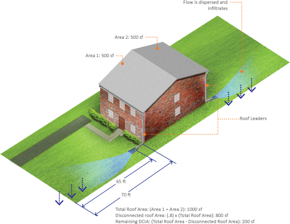
For example, consider a 1,000‑square foot roof with two roof leaders, each draining an area of 500 square feet (Figure 3.1‑2). Both roof leaders discharge to a lawn. The lawn has type B soils and a slope of 3%. The distance from the downspout discharge point to the street is 65 feet. Therefore, based on Table 3.1‑2, 80% of the roof area may be considered disconnected and treated as pervious cover when calculating stormwater management requirements. Disconnecting the roof leaders will significantly reduce the size and cost of stormwater management facilities at this site.
Figure 3.1‑2: Rooftop disconnection example
Roof leader disconnection can be incorporated into Stormwater Retrofit designs and is eligible for stormwater credit. The designer is referred to the Stormwater Management Service Charge Credits and Appeals Manual (Credits and Appeals Manual) for eligibility requirements.
Pavement disconnection
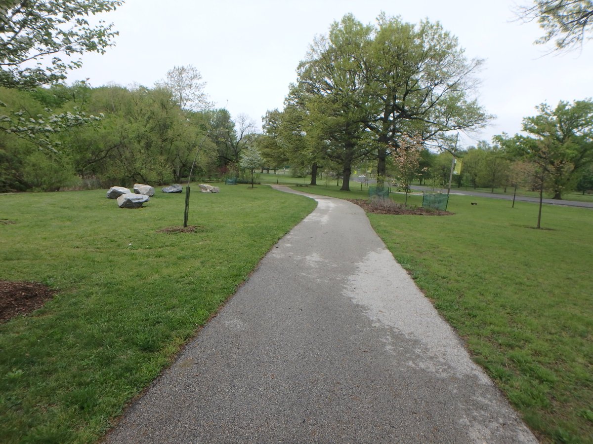
A reduction in DCIA is permitted when pavement runoff is directed to a vegetated area that allows for infiltration, filtration, and an increased time of concentration. This method is generally applicable to small or narrow pavement structures such as driveways and narrow pathways through otherwise pervious areas (e.g., a trail through a park).
Pavement is considered to be completely, or partially, disconnected if it meets all of the following requirements:
- The contributing flow path over impervious pavement is no more than 75 feet.
- The length and width of overland flow over pervious areas is greater than, or equal to, the length and width of the contributing flow path over impervious pavement.
- The overland flow is non-concentrated sheet flow over a vegetated area (flow through a swale is not eligible for pavement disconnection credit).
- The soil of the pervious area is not designated as a hydrologic soil group “D” or equivalent.
- The contributing impervious area has a slope of 5% or less.
- The overland flow path of the pervious area has a slope of 5% or less.
- If discharge is concentrated at one or more discrete points, no more than 1,000 square feet may discharge to any one point. In addition, an erosion control measure, such as a gravel strip, is required for concentrated discharges. Erosion control measures are not required for non-concentrated discharges along the entire edge of pavement; however, there must be provision for the establishment of vegetation along the pavement edge and temporary stabilization of the area until vegetation becomes established.
When choosing pavement disconnections, the designer should consider the impact of directing runoff from adjacent impervious areas on the pervious area. Disconnecting larger areas of pavement along stream banks and other potentially erosive or sensitive areas may necessitate additional measures to be taken beyond meeting the minimum requirements.
Pavement disconnection can be incorporated into Stormwater Retrofit designs and is eligible for stormwater credit. The designer is referred to the Credits and Appeals Manual for eligibility requirements.
Tree disconnection credit
A reduction in DCIA is permitted when existing or newly proposed tree canopy (with trees selected from an approved species list) extends over, or is in close proximity to, an impervious area. Trees planted in vegetated practices, such as bioinfiltration/bioretention areas, and that meet the requirements set forth in this section can be used toward tree disconnection credit.
Existing tree disconnection credit may be applied for a reduction in DCIA if it meets the following requirements:
- The existing tree species is not an invasive species. The designer is referred to Appendix I for more information.
- The existing tree is at least a four‑inch caliper.
- Existing tree canopies have been field measured, and tree location, size, and species are indicated on submitted plans. Alternatively, an annotated aerial photo clearly showing the existing tree canopy limits has been submitted.
- Only impervious area located directly under the tree canopy area is considered disconnected.
- Overlapping existing tree canopy area is not counted twice toward disconnection credit.
- Existing trees are located outside of the public right-of-way.
New tree disconnection credit may be applied for a reduction in DCIA if it meets the following requirements:
- The proposed tree species are chosen from Table I‑1, the recommended and native non-invasive plant list, in Appendix I.
- New trees are planted within ten feet of ground-level impervious area, within the limits of earth disturbance, and outside of the public right-of-way.
- New deciduous trees are at least two‑inch caliper.
- New evergreen trees are at least six feet tall.
- A 100‑square foot DCIA reduction is permitted for each new tree. This credit may only be applied to the impervious area adjacent to the tree.
- Overlapping 100‑square foot DCIA reduction areas corresponding to adjacent new trees cannot be counted twice toward disconnection credit.
The maximum reduction permitted for both new and existing trees is 25% of ground-level impervious area within the limits of earth disturbance, unless the width of the impervious area is less than ten feet. Up to 100% of narrow impervious areas (e.g., sidewalks and trails) may be disconnected through the application of tree credits.
Tree disconnection credit, as listed above, cannot be incorporated into Stormwater Retrofit designs, but a mature tree with canopy cover over unmanaged impervious area is eligible for Stormwater Credit. The designer is referred to the Credits and Appeals Manual for eligibility requirements.
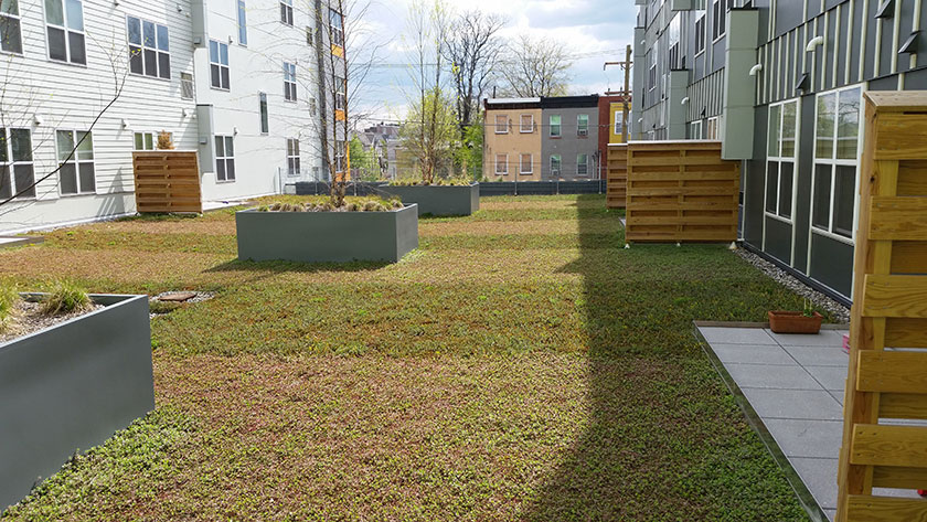
Green roof
A reduction in DCIA is permitted when a green roof is installed on a proposed building and when the design, construction, and maintenance plans meet the minimum requirements specified in Section 4.3. To encourage the use of this technology, the entire extent of the green roof area may be considered DIC. However, since a green roof is not a zero-discharge system, the remaining site design must safely convey roof runoff from larger storm events to an approved point of discharge. When performing calculations for Flood Control and Public Health and Safety (PHS) Release Rate requirements, green roof discharge (i.e., overflows) must be modeled using appropriate Natural Resources Conservation Service (NRCS) runoff Curve Number (CN) values for green roof areas as described in Section 3.4.3. The designer is referred to Section 4.3 for more information on green roofs.
Green roofs may be considered differently for Stormwater Retrofit projects. Designers wishing to incorporate green roofs into Stormwater Retrofit projects should contact Stormwater Billing and Incentives for additional information.
Porous surfaces
PWD recognizes two types of porous surface systems that can be used to achieve compliance with the Stormwater Regulations: porous surface DIC areas receiving direct rainfall only; and porous surface over a structural SMP, which is designed to manage direct rainfall and concentrated runoff from adjacent DCIA.
Porous surfaces can be considered DIC when they do not create any areas of concentrated infiltration and do not receive runoff from any adjacent impervious areas.
Porous surfaces over structural SMPs are not considered DIC and therefore must be designed pursuant to the requirements of either a subsurface infiltration (Section 4.4) or subsurface detention (Section 4.8) SMP, depending upon the feasibility of infiltration.
For disconnection credit, the design, construction, and maintenance plan must meet the minimum requirements or porous surfaces DIC, as specified in Section 4.2. When performing calculations for Flood Control and PHS Release Rate requirements, appropriate CN values must be used for porous surfaces, as described in Section 3.4.3.
Porous surfaces may be considered differently for Stormwater Retrofit projects. Designers wishing to incorporate porous surfaces into Stormwater Retrofit projects should contact Stormwater Billing and Incentives for additional information.
DIC Applications
There is a broad range of additional applications, including proprietary products, which may be suitable for receipt of disconnection credits. Many of these products will require the use of an appropriate sub-base to allow for storage and infiltration and must generally be installed above non-compacted soil. In most cases, underdrain systems are not required for DIC. The designer must consult with PWD Stormwater Plan Review for specific performance or installation parameters. Potential applications include, but are not limited to, the following:
- Trails (Section 3.5.4);
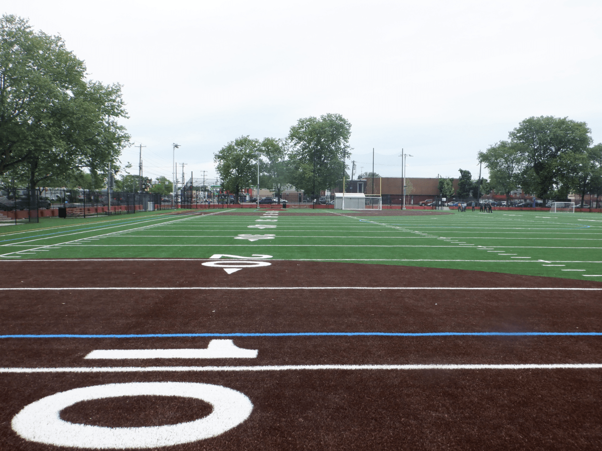
- Artificial, or synthetic, turf surfaces for athletic fields (Section 3.5.5);
- Porous safety surfaces as found in play lots;
- Geogrid systems or other similar reinforced turfs;
- Pervious decking installed over a porous surface; and/or
- Permeable paver tiles with porous grout or gaps.
How to use disconnection strategies to help comply with the Stormwater Regulations
The designer can use DIC to help comply with the Stormwater Regulations described in Chapter 1 in the following ways:
Water Quality and Channel Protection
For the strategies described above, impervious area meeting disconnection criteria is considered DIC; therefore, these projects are not subject to Stormwater Regulations concerning Water Quality and Channel Protection requirements for treatment of on-site DCIA. Implementing DIC can be an excellent strategy for managing small areas of DCIA for which routing the runoff to the proposed SMP is not feasible, such as porches, steps, concrete pads, walkways, or impervious cover atop utility trenching, etc. Additionally, Redevelopment projects that reduce impervious area within the limits of earth disturbance (excluding public right-of-way) by at least 20%—based on a comparison of predevelopment impervious area to post-development DCIA—are exempt from the Channel Protection requirement.
Flood Control
The use of some disconnection strategies such as green roofs and porous surfaces will generally increase on-site stormwater retention, thus reducing the amount and peak flow rate of stormwater required to be managed. Additionally, the use of disconnection strategies reduces DCIA. Redevelopment projects that reduce impervious area within the limits of earth disturbance (excluding public right-of-way) by at least 20%—based on a comparison of predevelopment impervious area to post-development DCIA—are exempt from the Flood Control requirement.
How disconnection design strategies influence the PWD review and approval process
Reducing DCIA through the implementation of DIC can influence the project Review Path, as described in Chapter 2. By incorporating DIC into the design of a Redevelopment project, developers may be eligible for an Expedited PCSMP Review (Section 2.4) to obtain PCSMP Approval faster and meet tighter construction schedules. Disconnection Green Review projects (Section 2.4.1) incorporate at least 95% DIC in the stormwater management design in order to meet the Stormwater Regulations, while Surface Green Review projects (Section 2.4.2) use a combination of bioinfiltration/bioretention SMPs and DIC to meet the Stormwater Regulations. Disconnection Green Reviews benefit from a shorter (five-day) PCSMP Review Phase and exemption from the infiltration testing requirement. Surface Green Review projects also benefit from a shorter (five-day) PCSMP Review Phase and the option to delay infiltration testing until construction to provide flexibility and potential cost savings.
3.1.6 SMP functions
The designer will often need to use SMPs to meet the Stormwater Regulations. PWD expects that the designer will first consider maximizing the use of non-structural design and DIC strategies outlined earlier in this chapter but also recognizes that, for many sites, stormwater management compliance will rely strongly on the use of SMPs.
SMPs are systems that use physical, chemical, and biological processes to provide a certain level of stormwater control and treatment. This level of control typically includes a required storage volume, a volume to be infiltrated, and an acceptable release rate. These requirements are met through five principal hydraulic functions of SMPs, described below.
Figure 3.1‑3 illustrates a variety of design elements available to provide these hydraulic functions. Depending on the configuration, physical, chemical, and biological processes lead to the removal of pollutants during these processes. By combining design components in a variety of ways, the designer can identify alternative systems that achieve a given function. The SMP functions are not mutually exclusive and certain SMPs may perform multiple functions.
Figure 3.1‑3: Overview of SMP functions
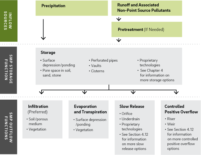
1. Storage
Storage can be provided through surface ponding, enclosed surface storage, or subsurface storage. Subsurface stone storage beds provide storage in stone pore spaces, or voids. Some SMPs, such as bioinfiltration/bioretention basins, can provide a combination of both surface and subsurface storage.
A rough estimate of surface storage can be obtained by averaging the surface area and bottom area of a basin and multiplying by the average depth. For irregular shapes, volume can be estimated by finding the area inside each contour, multiplying each area by the contour interval, and adding the results.
Storage in stone pores is equal to the volume of the crushed stone bed multiplied by the porosity. A design porosity of 40% can be assumed for the stone if specifications for the crushed stone meet those provided in Chapter 4.
Storage available in porous media is equal to the initial moisture deficit, the portion of total porosity that is not already occupied by moisture. This portion varies at the beginning of every storm; acceptable design values are 30% for sand and 20% for growing soil.
Not all physical space in a given SMP is active. The maximum elevation that is considered active storage is the overflow elevation. In tanks draining by gravity whose bottoms do not infiltrate, any volume below the invert of the orifice or control structure cannot be considered active storage.
2. Infiltration
Infiltration of stored water into the underlying soil is desired in order to help restore natural hydrology and reduce the volume of stormwater runoff that enters the City’s drainage system. Managing and infiltrating stormwater at its source reduces the risk of localized flooding and combined sewer overflows during heavy rainfall events, which are projected to occur more frequently with climate change. Moreover, the filtration process naturally aids in the removal of pollutants from stormwater runoff and improves the water quality of runoff entering our city’s waterways. Surface vegetation helps prolong design life because the growth of plant roots helps to keep the soil pore structure open over time. This effect is greatest with vegetation that has a deeper root structure (e.g., trees, shrubs, and native herbaceous species rather than turf grass). Using such attractive landscaping practices improves the quality of life in the urban landscape.
3. Evaporation and transpiration
Evaporation and transpiration are minor SMP functions when measured over the course of one storm, but they are significant when measured over time. Surface SMPs will provide the greatest evaporation and transpiration benefit, particularly if they are vegetated. Some water that infiltrates the surface will evaporate. For this reason, vegetated systems provide both water quality treatment and volume reduction.
4. Slow release
When stored water cannot be infiltrated or evaporated, it must be released at a slow rate to a sewer or receiving water body. This allows the runoff to slowly drain into the City’s system, preventing environmental issues stemming from large amounts of water entering the sewer system or receiving water all at once. For volumes greater than the SMP’s infiltrated static storage, and for non-infiltrating SMPs, the SMP may release the volume slowly through an outlet control device. The outlet control structure may require design and maintenance measures to avoid clogging.
5. Controlled positive overflow
All designs must have a mechanism for water to overflow, or bypass, the system unimpeded during events larger than the design event. A riser or other overflow structure can be incorporated into the design to achieve this, or the flow capacity of some SMPs themselves can act as a bypass mechanism.
3.1.7 Pollutant-reducing practices and roof runoff isolation
Pollutant-reducing practices
While infiltration is always preferred, Table 3.1‑3 presents a list of acceptable pollutant-reducing practices to be used for projects where infiltration is found to be infeasible. The designer is referred to the Chapter 4 section referenced in the table for detailed design information concerning each SMP type. Additional information on SMP types is provided later in this section within the SMP Selection and Conceptual Design Section. If a particular practice is listed as “not acceptable” within separate sewer or direct discharge areas, it does not imply that this practice cannot be used; it simply means that that particular practice does not qualify as pollutant-reducing when used in those areas.
Table 3.1‑3: Acceptable non-infiltrating pollutant-reducing practices
| Section | Combined sewer area | Separate sewer area or direct discharge | |
|---|---|---|---|
| Bioretention | 4.1 | Yes | Yes |
| Porous surfaces DIC | 4.2 | Yes | Yes |
| Green roofs | 4.3 | Yes | Yes |
| Blue‑green roofs | 4.14 | Yes | Yes |
| Cisterns | 4.5 | Yes | Yes |
| Blue roofs | 4.6 | Yes | No |
| Ponds and wet basins | 4.7 | Yes | Yes |
| Vegetated media filters | 4.9 | Yes | Yes |
| Media filters | 4.9 | Yes | Yes |
| Subsurface detention maintenance rows | 4.8, 4.9 | Yes | Yes |
| Roof runoff isolation* | 3.1.7 | Yes | No |
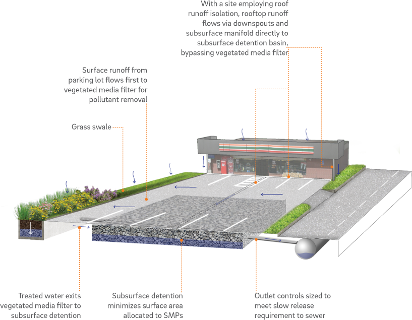
Roof runoff isolation
Recognizing that runoff from some areas is cleaner than others, PWD has identified roof runoff isolation as an acceptable non-infiltrating pollutant-reducing practice for use only on projects that are within combined sewer areas and required to comply with Stormwater Regulations. Roof runoff isolation is the practice of segregating roof runoff from runoff exposed to any vehicular activity (e.g., roof-level parking deck) and from untreated surface ground-level runoff, prior to discharging to the sewer.
The designer can incorporate roof runoff isolation into site layout and design by providing dedicated stormwater conveyance piping from roof areas to SMPs designed to meet the combined sewer area Water Quality slow-release rate requirement. A blue roof (Section 4.6) can also be used as streamlined approach for both achieving roof runoff isolation as well as controlling the roof runoff to meet the Water Quality slow-release requirement. Runoff from isolated roofs must not commingle with roof runoff exposed to vehicular activity or other untreated runoff until a point in the system after which such runoff has been treated by another pollutant-reducing practice. An example of an application of roof runoff isolation is illustrated in Figure 3.1‑4.
Figure 3.1‑4: Roof runoff isolation example
3.1.8 How to use SMPs to comply with the Regulations
A well-designed SMP will use combinations of the five principal hydraulic functions described above to achieve compliance with Stormwater Regulations. As noted previously, SMPs are one tool available to the designer to meet the Stormwater Regulations. PWD encourages the designer to first consider non-structural design and DIC to meet the Stormwater Regulations prior to considering SMPs (Section 3.1.4 and Section 3.1.5). Specific suggestions for using SMPs for compliance are discussed below. The designer should also consult the guidance on designing SMPs in series and Stormwater Management Banking and Trading in Sections 3.2.3 and 3.2.4, respectively, for additional options in using SMPs to help comply with the Stormwater Regulations.
Water Quality
Where infiltration is feasible, each SMP must provide adequate static storage for its entire Water Quality Volume (WQv) below its lowest outlet. Exceptions to this requirement include SMPs in series (for which the series as a whole must comply with this requirement) and dynamically designed bioinfiltration SMPs (for which static storage of only one inch of the WQv must be provided if the designer demonstrates, through dynamic routing, that the full 1.5‑inch WQv is managed throughout the design storm, without overflow). Additionally, the designer must ensure a drain down time of no more than 72 hours. Drain down time compliance is typically achieved by varying the storage area dimensions.
Where infiltration is not feasible in a combined sewer area, the WQv must be treated and released at a controlled release rate and routed through an acceptable pollutant-reducing practice. The designer is referred to Section 3.4.1 for detailed information on how to comply with the Water Quality requirement.
For gravity systems, the target-controlled release rate is a function of head on the outlet structure orifice/weir and the orifice/weir characteristics. Compliance is typically achieved by varying storage area dimensions and outlet structure configuration to meet the target slow-release rate.
Channel Protection (if applicable)
Compliance with the Channel Protection requirement is typically achieved by varying storage area dimensions and outlet structure configuration to reduce the peak outflow rate during the one‑year storm. Additionally, the designer must ensure a drain down time of no more than 72 hours. Controlled positive overflow must be provided, typically in the form of a riser or other overflow structure, to safely pass events larger than the one‑year design storm. The designer is referred to Section 3.4.1 for detailed information on how to comply with the Channel Protection requirement.
Flood Control (if applicable)
Compliance with the Flood Control requirement is also typically achieved by varying storage area dimensions and outlet structure configuration to reduce the peak outflow rates for the post-development condition. Peak runoff in the proposed condition must be no greater than the peak runoff in the predevelopment condition for design storms specific to a project’s given Flood Management District and discharge point. Controlled positive overflow must be provided, typically in the form of a riser or other overflow structure, to safely pass large storms. The designer is referred to Section 3.4.1 for detailed information on how to comply with the Flood Control requirement.