Download summaries of this SMP and its maintenance guidance, with quick reference information for clients and developers:
4.4.1 Subsurface infiltration introduction
Subsurface infiltration stormwater management practices (SMPs) are typically stone beds, or basins, with storage pipes beneath landscaped or paved surfaces. Stormwater flows into the subsurface infiltration SMP where it collects within the aggregate void space and infiltrates into the surrounding soil. Dry wells, infiltration trenches, and infiltration beds are a few examples of this SMP type.
Subsurface infiltration SMPs can be combined with other SMPs in series to meet the Philadelphia Water Department (PWD) Stormwater Regulations (Stormwater Regulations). The designer is referred to Section 3.2.3 for information on using SMPs in series.
Design of subsurface infiltration SMPs is not limited to the examples shown within this text. Successful stormwater management plans will combine appropriate materials and designs specific to each site.
When can subsurface infiltration be used?
Subsurface infiltration SMPs should be considered only if surface bioinfiltration/bioretention SMPs are not feasible on-site.
Subsurface infiltration SMPs must have underlying soils that, when tested pursuant to the infiltration testing procedure described in Section 3.3, are determined to be infiltration-feasible. They can be used to manage stormwater on both small and large sites. For large sites, multiple subsurface infiltration SMPs can be integrated throughout to manage larger areas.
Subsurface infiltration SMPs are versatile SMPs suitable for many types of development, from multi-family residential to high-density commercial projects. Provided that overburden loads and utility conflicts are evaluated, they can be sited beneath lawns and recreational areas, as well as parking lots and other hardscape surfaces.
Key advantages of subsurface infiltration
- Manages stormwater runoff without occupying surface or rooftop space
- Can be sited, through flexible design options, beneath lawns and recreational areas, as well as parking lots and other impervious areas when space constraints exist
- Can be a good option to meet the Flood Control requirement for constrained sites
Key limitations of subsurface infiltration
- Can be more costly and difficult to install and maintain than surface practices like bioinfiltration SMPs
- Not appropriate for runoff with high sediment loads without aggressive pretreatment
- Require strict adherence to regularly scheduled inspections because the maintenance needs are not easily visible
- Typically results in additional maintenance costs due to access limitations and Occupational Safety and Health Administration (OSHA) requirements
- Does not improve natural aesthetics or provide the ancillary environmental benefits associated with vegetated SMPs, such as habitat creation and improved air quality
Key design considerations for subsurface infiltration
- Appropriate pretreatment should be provided to remove sediment and debris before discharging to a subsurface infiltration system. A pretreatment approach should be developed based on the expected level of sediment loading and difficulty of sediment removal.
- Subsurface chambers, crates, pipes, or arches can be used to increase void space and reduce SMP footprint; however, proper analysis must be completed to ensure that loading ratio requirements are not exceeded.
- Long-term maintenance must also be carefully considered when evaluating such systems.
- The system and maintenance access should be located in an area where maintenance and potential repairs can be conducted with minimal disturbance to surrounding uses
- Structural suitability for overburden support and traffic loading should be considered, where applicable.
- Areas of soil contamination or unstable soils may need to be remediated or stabilized prior to subsurface infiltration SMP installation
- For any subsurface infiltration SMP that discharges onto an adjacent property, a drainage easement may be required and is recommended.
Subsurface infiltration types
Subsurface infiltration SMPs come in a variety of shapes and sizes, but commonly fit into the following three categories:
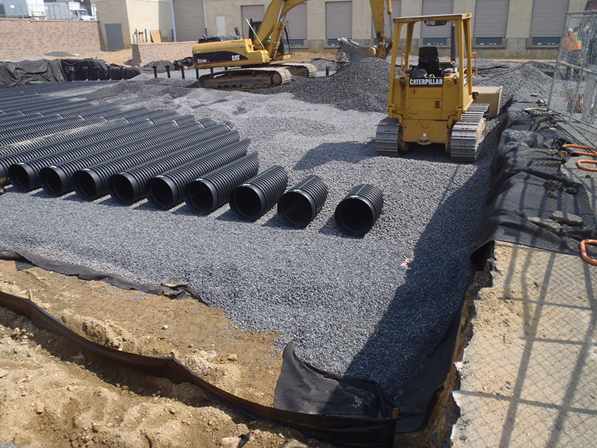
Underground stone storage consists of buried stone beds wrapped in geotextile that promote infiltration into subsoils. Stone storage beds provide the least amount of storage volume per unit area among the subsurface infiltration types. Removing sediment from underground stone storage is difficult, which necessitates effective pretreatment.
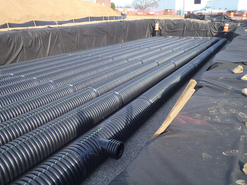
Underground pipe and chamber storage comprises perforated plastic or metal pipes, or pipe-like linear chambers, that are placed in a stone bed to provide more storage per unit volume and promote infiltration into subsoils. Various pipe dimensions and shapes can be used to optimize the storage volume to meet the specific site requirements. The designer is referred to Section 4.15 for information on drainage wells, a subsurface infiltration system that falls into this category.
Underground plastic grid storage consists of buried plastic structures that can be stacked and interconnected to form various shapes and sizes. Grid systems can provide as much as 95% void space for storage of stormwater.
4.4.2 Subsurface infiltration components
Figure 4.4‑1: Subsurface infiltration with typical features
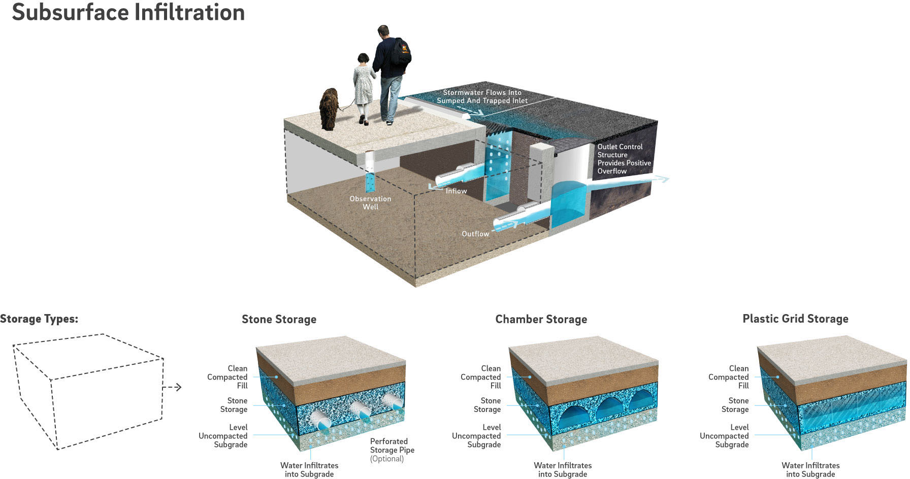
Pretreatment component
Pretreatment systems capture trash, sediment, and/or pollutants from stormwater runoff before delivery to the infiltration area. Pretreatment needs will vary significantly depending on the contributing drainage area composition and use. Pretreatment can include structures such as sumped and trapped inlets, sediment/grit chambers or separators, media filters, inlet inserts, or other appropriate prefabricated or proprietary designs to remove sediment, floatables, and/or hydrocarbons from stormwater runoff prior to being conveyed to a subsurface infiltration SMP. While inlet hoods are preferred, permanent filter bags may be accepted for Stormwater Retrofit projects where existing inlets do not have hoods and inlet reconstruction is not feasible. In addition to sumped and trapped inlets, permanent filter bag inserts are required for sites that generate pollutants such as loading docks, material storage facilities, junk yards, and waste collection and disposal sites. Permanent filter bags will require frequent cleanings.
Pretreatment can also consist of maintenance rows, filter strips, forebays, and swales. The designer is referred to Section 4.10, Pretreatment, for more information on pretreatment systems.
Inlet control component
Inlet control systems convey and control the flow of stormwater from the contributing catchment area to a subsurface infiltration SMP. Inlet control needs will vary depending on the design of stormwater conveyance systems and the site layout. The designer is referred to Section 3.4.2 for guidance on stormwater conveyance system design.
Inlet controls may include flow splitters, curbless design/curb openings, energy dissipaters, and inlets. The designer is referred to Section 4.11, Inlet Controls, for more information on inlet controls.
Storage area component
Storage areas within subsurface infiltration SMPs temporarily hold stormwater runoff as it infiltrates into native soils. The storage component of a subsurface infiltration SMP is typically constructed of a stone-filled, level-bottomed bed or trench, which may or may not incorporate pipes, arches, concrete vaults, crates, plastic grids, or other proprietary structures. The void spaces between the stones and/or structures store stormwater until it can infiltrate into the surrounding soils.
Outlet control component
Outlet controls within a subsurface infiltration SMP can provide a range of functions, including the following:
- Controlling how much water is stored for infiltration;
- Meeting drain down time requirements;
- Controlling the rate of discharge from the SMP and limiting water surface elevations during various storm events; and/or
- Bypassing of flows from large storm events.
Outlet controls may include orifices, weirs, or level spreaders. The designer is referred to Section 4.12, Outlet Controls, for more information on outlet controls.
Inspection and maintenance access component
Safe and easy inspection and maintenance access to all major components within a subsurface infiltration SMP is critical to ensuring long-term performance. Access points provide access to subsurface systems, both for inspections and routine maintenance, and for pumping water out of subsurface SMPs in cases of failure or severe damage. Manholes provide access for maintenance personnel and equipment to perform maintenance and inspections. Cleanouts provide access for hoses and vacuum equipment. Observation wells provide access to the bottom of subsurface systems for performance inspections and monitoring. Access structures may also serve additional functions, such as joining subsurface pipes.
4.4.3 Subsurface infiltration design standards
General design standards
- The maximum allowable drain down time is 72 hours after the 24‑hour storm event.
- The maximum allowable directly connected impervious area (DCIA) to SMP footprint loading ratio is 10:1.
- Positive overflow must be provided for large storm events, up to and including the 100‑year, 24‑hour storm, or, if the project is exempt from Flood Control, the ten‑year, 24‑hour storm. Overflow structures and pipes must be designed to convey at least the ten‑year, 24‑hour storm.
- The minimum allowable distance between subsurface infiltration basins and any adjacent private property line is ten feet. This includes partially lined basins. It is acceptable for SMPs to be located directly adjacent to the public right-of-way (ROW).
- The minimum allowable distance between subsurface infiltration basins and any building or retaining wall is ten feet. This includes partially lined basins. The following requirements and exceptions apply:
- For existing and proposed buildings with basements, the setback is measured from the basement wall.
- For existing buildings without basements and existing retaining walls, the setback is measured from the foundation and may be waived if a signed and sealed geotechnical analysis is submitted that evaluates the impacts of infiltration and excavation on the existing foundation and determines it to be feasible.
- For proposed buildings without basements and proposed retaining walls, the setback is measured from the foundation and may be waived if the foundation is proposed to be designed with the basin’s proximity in mind.
- Infiltration requirements:
- The designer is referred to Section 3.3 for information on infiltration testing requirements.
- The SMP must be located at least two feet above any poorly infiltrating soils, seasonal high groundwater table, bedrock, or any other limiting zone.
- For hydrologic modeling, infiltration must be applied to the horizontal surface area (SMP footprint), not the wetted area.
- Soils underlying infiltration practices must, when tested pursuant to the infiltration testing procedure described in Section 3.3, be determined to be infiltration feasible. If infiltration feasibility is unknown and determination is deferred until construction, the applicant must submit two complete designs (e.g. plans, calculations, Online Technical Worksheet, etc.) for both infiltrating and non-infiltrating scenarios to be fully reviewed. A PCSMP Conditional Approval will be issued, and the approval letter will feature both plan sets. Following infiltration testing, only the applicable design’s plan set will be included on the PCSMP Approval Letter.
- Soils with rates in excess of ten inches per hour require soil amendments. During construction, upon achieving final subgrade elevations, a two‑foot-thick layer of amended soil must be placed across the entire cross-section of the infiltrating SMP, below the bottom elevation of the SMP, and a minimum of three infiltration tests must be performed within the amended soil layer. If soil amendments are installed and the tested infiltration rate is determined to be outside of the PWD-allowable range or varies significantly from the design infiltration rate, additional soil amendments and/or a SMP redesign will be required. The designer is referred to Section 3.3 for additional detail.
- If the infiltration SMP is used as a temporary sediment basin during construction, the invert elevation of the infiltration SMP must be a minimum of three feet below the bottom elevation of the pre-basin-conversion sediment basin.
- An infiltrating SMP within the zone of influence of any nearby sewers or sewer laterals must be installed with an impervious liner. The zone of influence is defined by the area within a 1:1 (H:V) slope line from the outer edge of a sewer or sewer lateral.
- Structural suitability for overburden support and traffic loading must be considered, where applicable.
Pretreatment design standards
- Acceptable form(s) of pretreatment must be incorporated into design. Pretreatment of runoff from all inlets is required. At a minimum, this can be achieved through the use of sumps and traps for inlets, sump boxes with traps downstream of trench drains, and filter strips for overland flow.
- The designer is referred to Section 4.10, Pretreatment, for more information on design standards for pretreatment systems.
Inlet control design standards
- The designer is referred to Section 4.11, Inlet Controls, for information on design standards for inlet control systems.
Storage area design standards
- The storage area must provide static storage for the Water Quality Volume (WQv) between the bottom elevation of the SMP and the elevation of the lowest outlet, including storage voids. Storage or distribution pipes alone are not sufficient in providing static storage. A minimum of at least three inches of forced storage via an outlet control device is recommended in order to give the statically stored volume time to infiltrate.
- The maximum allowable static storage volume without supporting documentation (defined below) is the runoff volume from the one‑year, 24‑hour storm.
- The maximum allowable static storage volume with supporting documentation is the runoff volume from the ten‑year, 24‑hour storm. Requirements for supporting documentation include a letter, signed and sealed by both the geotechnical and design engineer, indicating that the proposed design is recommended, with the following components acknowledged and considered. The designer is encouraged to contact PWD for further guidance when pursuing this design.
- A summary of the long-term impacts to the neighboring properties, including, but not limited to subsidence, change in basement moisture/ water, and structural damage;
- The location of the groundwater table;
- References to other projects that have successfully infiltrated more than the one‑year, 24‑hour storm event; and
- Rigorous pretreatment to promote longevity of the infiltration SMP.
- When SMPs are used in series, the storage areas for all SMPs must provide cumulative static storage for the WQv, but there is no minimum storage requirement for each individual SMP used in series.
- Subsurface infiltration SMPs can be designed with additional storage beyond the WQv and with outlet controls that allow all remaining applicable Stormwater Regulations to be met.
- Void space provided by linear chamber systems, plastic grids, or other related structures must be as specified by the manufacturer and noted in supporting documentation.
- Bedding and foundations:
- Pipe, vault, grid, and chamber storage areas must be adequately bedded with stone to prevent settling or subsidence.
- Bedding thickness must vary according to system requirements but must not be less than six inches.
- Over-excavation and replacement of loose or unstable subsurface material may be required if such conditions are encountered. A geotechnical engineer or other appropriate design professional should be consulted for additional guidance.
- Foundations/footers must be provided as warranted by system loading, geotechnical conditions, and manufacturer’s recommendations. Foundation designs must be performed by an appropriate design professional.
- The storage design must account for potential loading from vehicles, as appropriate, based on expected maximum active loading, including consideration for emergency vehicles.
- Porosity values for storage volume calculations are as follows:
- Soil media: 0.20
- Sand: 0.30
- Stone: 0.40
- Stone must be separated from soil media by a geotextile or a pea gravel filter to prevent sand, silt, and sediment from entering the system.
- Stone storage systems must have a level bottom or use a terraced system if installed along a slope.
Outlet control design standards
- The designer is referred to Section 4.12, Outlet Controls, for information on design standards for outlet control systems.
Inspection and maintenance access design standards
- Cleanouts, manholes, access panels and other access features must be provided to allow unobstructed and safe access to SMPs for routine maintenance and inspection of inflow, outflow, underdrains, and storage systems.
- Observation wells must be provided for SMPs that include stone storage and must meet the following requirements:
- The observation well must be placed at the invert of the stone bed.
- The observation well must be located near the center of the stone bed system to monitor the level and duration of water stored within the SMP (drain down time). A minimum of six inches of clearance must be provided between the edge of the observation well’s concrete ring or frame and any nearby site features (curbing, tree pits, sidewalk edge, etc.). Plan view dimensioning for the proposed location of the observation well, relative to the boundaries of the SMP it lies within, must be provided on the plans.
- Adequate inspection and maintenance access to the observation well must be provided.
- An observation well located in a paved area must be outfitted with a cover and frame. The cover plate must be installed flush with the surrounding surface at finished grade, and grading should drain away from the observation well wherever possible. The solid section of the observation well must extend into the cover frame enough such that a bentonite/cement seal can be placed around the well within the frame, and a solid slip-on cap can be fitted onto the pipe end.
- An observation well located in an unpaved area must have a concrete ring or frame poured for support, with three lengths of rebar evenly spaced around the ring and three inches from its outer edge. The observation well should be located outside of the ponding area of any surface SMPs. If, due to space limitations, an observation well must be placed in the ponding area of a surface SMP, the concrete ring and well cover must extend three inches above the SMP’s maximum ponding depth.
- The observation well must include a slotted section within the storage layer of the SMP. The top of the slotted well section must extend to a minimum of six inches below the top of the SMP storage layer, and the slotted section must extend down the entire depth of the SMP.
- Access features for subsurface infiltration SMPs:
- Access features must be provided for all underground storage SMPs that are not stone storage beds.
- A sufficient number of access points in the SMP must be provided to efficiently inspect and maintain the infiltration area.
- For cast-in-place vault systems, access features must consist of manholes or grated access panels or doors. Grated access panels are preferred to maintain airflow.
- For grid storage or other manufactured systems, the manufacturer’s recommendations must be followed.
- Ladder access is required for vaults greater than four feet in height.
- Header pipes, at minimum 36‑inch diameter, connected to manholes at each corner of the subsurface infiltration SMP must be provided. Alternatively, smaller header pipes may be used if cleanouts are provided on the manifold/header pipe junction for each distribution pipe. The cleanouts must be on alternating sides of the SMP.
Figure 4.4‑2: Subsurface infiltration basin (pipe in stone) standard detail
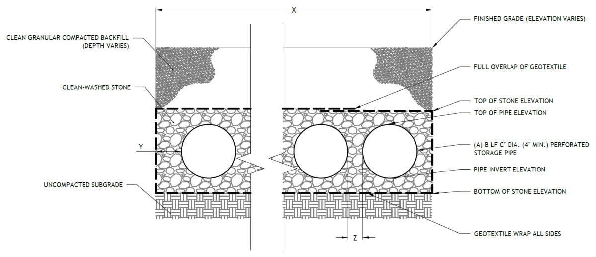
(The designer is referred to Appendix L to download Standard Detail CAD files.)
4.4.4 Subsurface infiltration material standards
Pretreatment material standards
- The designer is referred to Section 4.10, Pretreatment, for information on materials standards for pretreatment systems.
Inlet control material standards
- The designer is referred to Section 4.11, Inlet Controls, for information on material standards for inlet control systems.
Storage area material standards
- Stone designed for stormwater storage must be uniformly graded, crushed, clean-washed stone. PWD defines “clean-washed” as having less than 0.5% wash loss, by mass, when tested per American Association of State Highway and Transportation Officials (AASHTO) T-11 wash loss test. AASHTO No. 3 and No. 57 stone can meet this specification.
- Sand, if used, must be AASHTO M‑6 or ASTM C‑33 sand and must have a grain size of 0.02 inches to 0.04 inches.
- Storage pipes:
- Pipe used within the subsurface infiltration SMP must be continuously perforated and have a smooth interior with a minimum inner diameter of four inches.
- High-density polyethylene (HDPE) pipe must meet the specifications of AASHTO M252, Type S or AASHTO M294, Type S.
- Any pipe materials outside the SMP are to meet City Plumbing Code Standards.
- Geotextile must consist of polypropylene fibers and meet the following specifications (AASHTO Class 1 or Class 2 geotextile is recommended):
- Grab Tensile Strength (ASTM-D4632): ≥ 205 lbs
- CBR Puncture Strength (ASTM-D6241): ≥ 500 lbs
- Flow Rate (ASTM-D4491): ≥ 95 gal/min/ft2
- UV Resistance after 500 hours (ASTM-D4355): ≥ 70%
- Tear Resistance (ASTM-D4533): ≥ 80 lbs
- Heat-set or heat-calendared fabrics are not permitted.
Outlet control material standards
- The designer is referred to Section 4.12, Outlet Controls, for information on material standards for outlet control systems.
Inspection and maintenance access material standards
- Observation wells:
- The observation well must consist of slotted plastic pipe with a minimum inner diameter of four inches and a solid cap at the surface. The slotted section of the well must consist of PVC slotted well screen with 0.01‑inch slot size and an attached perforated PVC cap at the bottom.
- The observation well’s cover must be ductile iron in a gray iron frame.
- For an observation well located in an unpaved area, the well’s concrete ring must be a minimum of six inches wider in any dimension than the cover frame, of equal depth as the cover frame itself, and poured atop a minimum of six inches of AASHTO #57 stone bedding. A frame conforming to these minimum dimensions may be circular or square.
- Cleanouts must be made of material with a smooth interior having a minimum inner diameter of six inches. If the connecting pipe is eight inches in diameter or larger, then the cleanout must be eight inches in diameter.
4.4.5 Subsurface infiltration construction guidance
Proper construction and careful consideration of soil compaction, infiltration performance, and sedimentation control of subsurface infiltration SMPs are essential to ensure long-term functionality and reduce long-term maintenance needs and costs. Since subsurface infiltration SMPs are, by definition, buried, construction oversight is critical. At a minimum, verification of volumes, grades, and elevations must be performed prior to backfill.
- Areas for proposed subsurface infiltration SMPs must be physically marked as heavy equipment exclusion zones prior to any land-disturbing activities to avoid soil disturbance and compaction during construction. Install construction fencing around subsurface infiltration areas. If areas are compacted during construction, additional infiltration testing and potential redesign efforts may be required.
- Provide erosion and sedimentation control protection on the site such that construction runoff is directed away from the proposed subsurface infiltration SMP. Sediment deposited in a subsurface infiltration SMP during construction, particularly a stone bed, can significantly reduce SMP performance. The designer is referred to the latest edition of the Pennsylvania Department of Environmental Protection (PA DEP) Erosion and Sediment Pollution Control Program Manual for information on design standards for erosion and sedimentation control practices.
- Infiltration areas may not be used as sediment traps during construction, unless at least three feet of soil are left in place while the area is serving as a sediment trap and subsequently removed during construction after the contributing drainage areas have been stabilized.
- Complete site elevation grading and stabilize all disturbed soil. Stabilization of disturbed areas must be implemented before finalizing the subsurface infiltration SMP’s excavation and construction.
- Excavate subsurface infiltration area to proposed depth and manually grade and scarify the existing soil surface. The bottom of the infiltration bed must be at a level grade.
- Existing subgrade must NOT be compacted or subject to excessive construction equipment prior to placement of geotextile and stone bed. The use of machinery to load stone from outside of the infiltration bed footprint is recommended. Stone should be carefully placed, not dumped, in the infiltration bed. If it is essential that equipment be used in the excavated area, all equipment must be low ground pressure equipment and approved by PWD. Use of equipment with narrow tracks or tires, rubber tires with large lugs, or high-pressure tires will cause excessive compaction and must not be used. Should the subgrade be compacted during construction, additional testing of soil infiltration rates and SMP redesign may be required. Rock construction entrances must not be located on top of areas proposed for infiltration practices.
- Place geotextile and stone aggregate immediately after approval of subgrade preparation to prevent accumulation of debris or sediment. Prevent runoff and sediment from entering the infiltration bed during the placement of the geotextile and aggregate bed.
- Place geotextile in accordance with manufacturer’s standards and recommendations. Secure geotextile at least four feet outside of bed. Adjacent strips of filter fabric must overlap a minimum of 16 inches
- Install aggregate course in lifts of six to eight inches. Lightly compact each layer with equipment, keeping equipment movement over storage bed subgrades to a minimum. Install aggregate to grades indicated on the drawings.
- All stone that makes up the infiltration SMP must remain free of sediment. If sediment enters the stone, the contractor may be required to remove the sediment and replace with clean washed stone.
- Confirm and document invert elevations and dimensions for all structures such as chambers and pipes prior to backfill.
- Backfill to finished grade. Ensure backfill is properly compacted in accordance with specifications. Ensure backfill process does not disrupt pipe placement and configuration.
- Structures such as inlet boxes, reinforced concrete boxes, inlet controls, and outlet controls must be constructed according to manufacturer’s guidelines or design professional’s guidance.
- Complete surface grading above subsurface infiltration SMP, using suitable equipment to avoid excess compaction.
- Once the site is permanently stabilized with vegetation, remove temporary erosion and sediment control measures.
4.4.6 Subsurface infiltration maintenance guidance
Maintenance of subsurface infiltration SMPs focuses on the periodic removal of sediment and debris from pretreatment and storage areas. Sediment removal from vaults, chambers, and pipes is typically conducted using vacuum or flushing systems. Guidance on the use and operation of vacuum or flushing sediment removal equipment is beyond the scope of this Manual; a maintenance professional should be contacted for additional details. As applicable, subsurface SMP maintenance procedures must meet OSHA confined space entry requirements.
General recommended maintenance activities for subsurface infiltration SMPs are summarized in Table 4.4‑1.
Table 4.4‑1: Subsurface infiltration maintenance guidelines
| Early maintenance activity | Frequency |
|---|---|
| Inspect erosion control and flow spreading devices until soil settlement and vegetative establishment of contributing areas has occurred. | Biweekly |
| Inspect inlet controls, outlet structures, and storage areas for trash and sediment accumulation. | Monthly for the first year after installation to determine ongoing maintenance frequency |
| Ongoing maintenance activity | Frequency |
|---|---|
| Regularly clean out gutters and catch basins to reduce sediment load to infiltration SMP. Clean intermediate sump boxes, replace filters, and otherwise clean pretreatment areas in directly connected systems. | As needed |
| Remove sediment and debris from subsurface infiltration SMP sedimentation chamber, as applicable, when the sediment zone is 3/4 full. Sediment and debris build‑up may need to be removed by a professional. Consult with a professional as necessary. | As needed |
| Remove sediment and debris from pipe/vault systems. Sediment depth is not to reach a maximum depth of four inches below the SMP’s outlet invert elevation. Removal of sediment from grid systems must be per manufacturer’s recommendations or as per the site-specific maintenance plan. | As needed |
| Replace filter bags for pretreatment devices. Ensure filter bag is installed properly. | Quarterly |
| Inspect subsurface infiltration facility and control structures. | Quarterly |
| Remove floating debris and accumulated petroleum products from system and all components. | Quarterly |
| Evaluate the drain down time of the SMP after a storm of at least one inch to ensure a SMP drain down time of less than 72 hours. | Ongoing |
| Maintain records of all inspections and maintenance activity. | Ongoing |
The designer is referred to Section 4.10, Pretreatment, Section 4.11, Inlet Controls, and Section 4.12, Outlet Controls, for information on maintenance guidance for pretreatment, inlet controls, and outlet controls.