Download summaries of this SMP and its maintenance guidance, with quick reference information for clients and developers:
4.15.1 Drainage well introduction
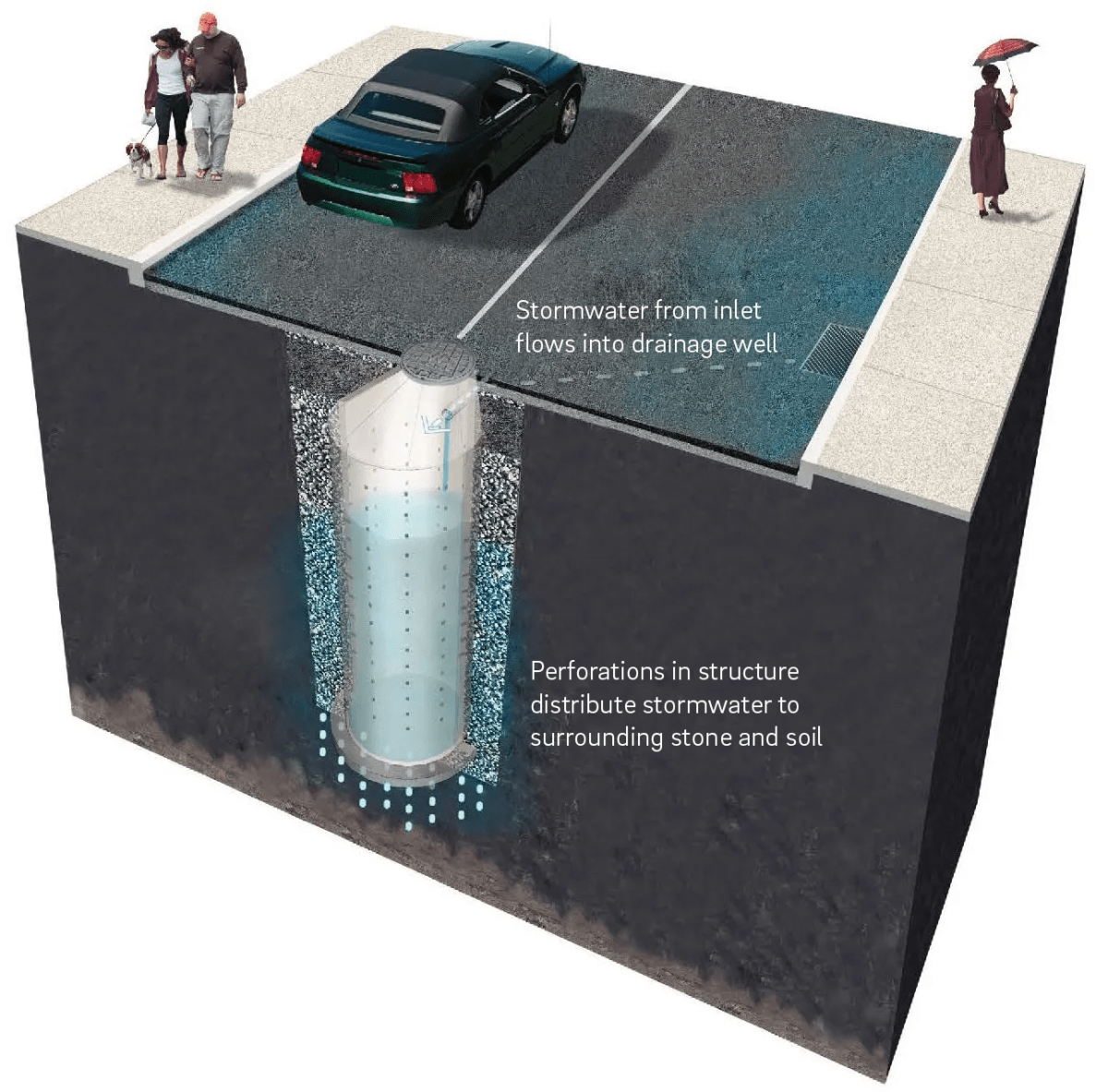
Drainage well stormwater management practices (SMPs) are perforated stormwater manholes that detain runoff and allow it to infiltrate into the surrounding soil. Stormwater flows into the drainage well where it collects within the manhole structure and surrounding open-graded stone. Drainage wells are typically constructed from precast concrete or a thermoplastic (typically polyvinyl chloride, or PVC). Drainage wells are a specific application of subsurface infiltration and are typically deeper than other types of infiltration SMPs. The designer is referred to Section 4.4 for more general information on subsurface infiltration SMPs.
Drainage wells can be combined with other SMPs in series to meet the Philadelphia Water Department (PWD) Stormwater Regulations (Stormwater Regulations). The designer is referred to Section 3.2.3 for information on using SMPs in series.
This design guidance provides flexibility for designers to dynamically model drainage wells. Dynamic routing allows designers to account for the volume of water infiltrated into the ground in real time, which allows the drainage well to have less storage and be shallower. Design of drainage wells is not limited to the examples discussed within this text. Successful stormwater management plans will combine appropriate materials and designs specific to each site.

Where can drainage wells be used?
Drainage wells must have underlying soils that, when tested pursuant to the protocol described later in this section (Section 4.15.3), are determined to be infiltration-feasible. They can be used to manage stormwater on both small and large sites, but may be especially useful on smaller sites, where open space for bioinfiltration/bioretention SMPs and horizontal area for subsurface infiltration are limited. For large sites, multiple drainage wells can be integrated throughout the site to manage larger areas. Provided that overburden loads and utility conflicts are evaluated, they can be sited beneath lawns and recreational areas, as well as parking lots and other hardscape surfaces. Drainage wells can also be dynamically sized to save space or reduce the depth of the SMPs.
Key advantages of drainage wells
- Can be useful on smaller sites with limited area available for bioinfiltration or subsurface infiltration footprints
- Can be easier to maintain than other subsurface infiltration types
- Less reliant on infiltration through the bottom surface of the SMP than other subsurface infiltration SMPs. Therefore, reduction in infiltration through the bottom of the SMP as a result of clogging may not be as detrimental to the long-term performance of drainage wells as it is to other subsurface infiltration SMPs.
- Eligible for dynamic sizing
Key limitations of drainage wells
- Can be more costly and more challenging to install than surface practices like bioinfiltration SMPs, as well as more difficult to maintain post-construction
- Because identification of the seasonal high-water table is so important to the design of a drainage well, and because drainage wells are generally deeper than other subsurface SMPs, monitoring of the water table over a period of time using groundwater monitoring wells is recommended. Monitoring may lengthen the time needed for design. Furthermore, if monitoring reveals a water surface elevation that is too high for the drainage well to function properly, alternate siting or an alternate design would be necessary.
- Not appropriate for runoff with high sediment loads without robust pretreatment
- Requires regularly scheduled inspections because the maintenance needs are not easily visible
- Does not improve natural aesthetics or provide the ancillary environmental benefits associated with vegetated SMPs, such as habitat creation and improved air quality
Key design considerations for drainage wells
- Must be constructed in soils suitable for infiltration. Infiltration in both vertical and horizontal directions should be considered.
- Drainage wells can be dynamically designed, which may save space or reduce the depth of the SMPs. These SMPs must statically store one inch of runoff and be shown, via dynamic routing, to manage 1.5 inches of runoff throughout the design storm, without overflow.
- The horizontally exfiltrating section of the drainage well should not be constructed in unstable fill. Designers are specifically cautioned against siting drainage wells in inappropriate fill high in ash, cinder, or brick fragments, which are prone to dissolving or washout. Horizontal infiltration should occur below any problematic fill.
- Must confirm depth to bedrock, water table, or other hydraulically limiting layers.
- Because drainage wells may be deeper than other subsurface infiltration SMPs, careful identification of the seasonal high water table is especially important. Continuous soil borings from the surface to a depth five feet below the proposed drainage well bottom is required. Further drilling to the observed water surface elevation and installation of a groundwater monitoring well and monitoring of the water surface elevation over a period of time (generally, from March through October) are recommended. Monitoring data and evaluation of samples from the continuous soil borings should be used to physically identify the seasonal high groundwater table. This must be reported in the Geotechnical Report, further outlined in Section 3.3.
- Appropriate pretreatment should be provided to remove sediment and debris before discharging to a drainage well system. A pretreatment approach should be developed based on the expected level of sediment loading and difficulty of sediment removal.
- Manhole structure diameter, the dimensions of the surrounding open-graded stone, and the depth of the drainage well system should be adjusted to provide appropriate runoff volume storage and management.
- Long-term maintenance must be carefully considered when evaluating drainage well systems. The system and maintenance access should be located in an area where maintenance and potential repairs can be conducted with minimal disturbance to surrounding uses.
- Improper installation of manholes has been known to result in subsidence in the area directly around the manhole. Proper compaction of stone and suitability of surrounding soils must be verified to minimize subsidence in the area around the drainage well.
- Structural suitability for overburden support and traffic loading should be considered, where applicable.
- Areas of soil contamination or unstable soils may need to be remediated or stabilized prior to drainage well installation.
- For any drainage well that discharges onto an adjacent property, a drainage easement is required.
Drainage well materials
Drainage wells may be designed and constructed in a variety of sizes and materials. In this section, we discuss two main types of material:
Precast concrete drainage wells consist of a perforated, reinforced precast concrete manhole, with cast iron frame and cover, surrounded by open-graded stone. Precast concrete drainage wells are typically designed for AASHTO HS-20 loading and are therefore able to be used under areas that experience vehicle traffic, like driveways and parking lots.
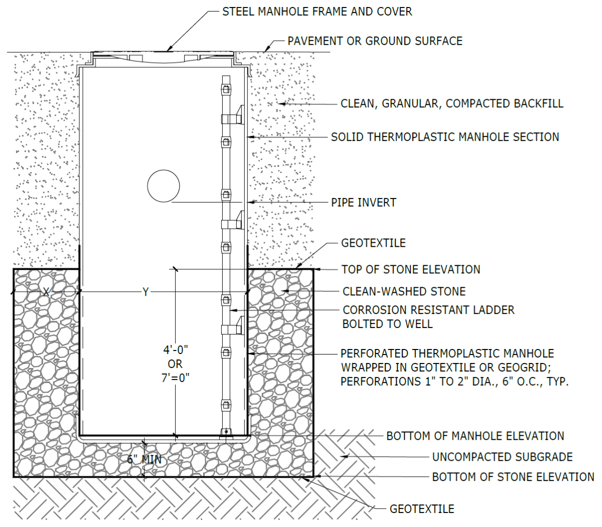
Thermoplastic drainage wells consist of a perforated, thermoplastic (typically PVC) manhole, with steel frame and cover, surrounded by open-graded stone. Thermoplastic drainage wells are typically designed for AASHTO H-20 loading and are therefore able to be used under areas that experience vehicle traffic, like driveways and parking lots. However, precast concrete drainage wells may be preferable where heavy vehicle loads are anticipated.
4.15.2 Drainage well components
Figure 4.15‑1: Precast concrete drainage well with typical features
Pretreatment component
Pretreatment systems capture trash, sediment, and pollutants from stormwater runoff before delivery to the infiltration area. Pretreatment needs will vary significantly depending on the contributing drainage area composition and use. Pretreatment can include structures such as sumped and trapped inlets, sediment/grit chambers or separators, media filters, inlet inserts, or other appropriate prefabricated or proprietary designs to remove sediment, floatables, and/or hydrocarbons from stormwater runoff prior to being conveyed to a drainage well. Pretreatment can also consist of filter strips, forebays, and swales. The designer is referred to Section 4.10, Pretreatment, for more information on pretreatment systems.
Inlet control component
Inlet control systems convey and control the flow of stormwater from the contributing catchment area to a drainage well. Inlet control needs will vary depending on the design of stormwater conveyance systems and the site layout. The designer is referred to Section 3.4.2 for guidance on stormwater conveyance system design.
Inlet controls may include flow splitters, curbless design/curb openings, energy dissipaters, and inlets. The designer is referred to Section 4.11, Inlet Controls, for more information on inlet controls.
Storage area component
Storage areas within drainage wells temporarily hold stormwater runoff as it infiltrates into surrounding soils. The storage component of a drainage well is typically constructed of a perforated precast concrete or thermoplastic manhole, surrounded by open-graded stone. The open space within the manhole and the void spaces between the stones store stormwater until it can infiltrate into the surrounding soils. Accounting for these void spaces, the drainage well’s storage volume may be calculated using the width of excavation measured at the extents of the stone surrounding the well (i.e. excavation diameter) and the depth of the well from the bottom of the stone to the overflow invert (i.e. infiltrating depth).
Outlet control component
Outlet controls within a drainage well can provide a range of functions, including the following:
- Controlling how much water is stored for infiltration;
- Meeting drain down time requirements;
- Controlling the rate of discharge from the SMP and limiting water surface elevations during various storm events; and/or
- Bypassing of flows from large storm events
Outlet controls may include orifices or overflow pipes. The designer is referred to Section 4.12, Outlet Controls, for more information on outlet controls. Typically, a separate structure outside the drainage well manhole is needed to regulate discharge from a drainage well that does not infiltrate into surrounding soils.
Inspection and maintenance access component
Safe and easy inspection and maintenance access to all major components within a drainage well system is critical to ensuring long-term performance. Access points provide access to the drainage well manhole as well as inlet and outlet controls, both for inspections and routine maintenance.
4.15.3 Drainage well design standards
If infiltration is deemed feasible, the designer may elect to dynamically design the drainage well. The dynamically designed SMP must still meet all applicable requirements, but it may be designed to statically store one inch of runoff, rather than the full 1.5‑inch Water Quality Volume (WQv). If this strategy is chosen, the designer must show, via dynamic routing, that the full 1.5‑inch WQv is managed throughout the design storm, without overflow.
General design standards
- The maximum allowable drain down time is 72 hours after the 24‑hour storm event.
- There is no maximum directly connected impervious area (DCIA) to SMP footprint loading ratio.
- Positive overflow must be provided for large storm events, up to and including the 100‑year, 24‑hour storm, or, if the project is exempt from Flood Control, the ten‑year, 24‑hour storm. Overflow structures and pipes must be designed to convey at least the ten‑year, 24‑hour storm.
- The minimum allowable distance between the edge of a drainage well’s stone storage bed and any adjacent private property line is ten feet. It is acceptable for drainage wells to be located directly adjacent to the public right-of-way (ROW).
- The minimum allowable distance between the edge of a drainage well’s stone storage bed and any building or retaining wall is ten feet. The following requirements and exceptions apply:
- For existing and proposed buildings with basements, the setback is measured from the basement wall.
- For existing buildings without basements and existing retaining walls, the setback is measured from the foundation and may be waived if a signed and sealed geotechnical analysis is submitted that evaluates the impacts of infiltration and excavation on the existing foundation and determines it to be feasible.
- For proposed buildings without basements and proposed retaining walls, the setback is measured from the foundation and may be waived if the foundation is proposed to be designed with the drainage well’s proximity in mind.
- When siting two or more drainage wells near each other, the lateral clearance between the edges of their stone storage beds must be twice the distance of the height of the perforated well section.
- Infiltration requirements:
- The drainage well must be located at least two feet above any poorly infiltrating soils, seasonal high groundwater table, bedrock, or other hydraulically limiting zone.
- For hydrologic modeling, a soil permeability coefficient (k20), calculated per the protocol described below in 7c(vi), must be applied to the wetted area of the drainage well, spanning the perforated sides and bottom, to determine infiltration characteristics.
- Because drainage wells utilize infiltration through the bottom as well as the sides, the infiltration testing protocol is different than other for other subsurface infiltration SMPs. Infiltration testing for drainage wells must be performed according to the following procedure, which is a modified version of the United States Bureau of Reclamation (USBR) Procedure 7300, Performing Field Permeability Testing by the Well Permeameter Method:
- Install a PVC well cap on one end of a four‑inch inner diameter, Schedule 40 PVC well screen and lower into a borehole (ASTM D6151‑08). The cap should be securely attached, making a positive seal. Sections of well screen should be added corresponding to the proposed length of perforated sections of the planned drainage well.
- A section of solid PVC casing corresponding to the depth below the ground surface to the top of the drainage well perforations should be connected to the slotted well screen section and extended to the ground surface.
- PVC well screen shall be new and flush threaded as per ASTM standards (ASTM D6724). The slot size of the well screen should be 0.060 inches (60 slot). The annulus between the well screen and the borehole should be filled with gravel pack, U.S. Silica FilPro #4 or equivalent.
- Infiltration testing shall be conducted by measuring the flow rate that is needed to maintain a constant head in the well. Use of a reservoir and float valves as described in USBR 7300 is suitable, but not required. Variations to the reservoir set up and the maintenance of the constant head are permitted as long as measurement of flow can be accurately made. Constant head should be maintained within one foot of the surface (keeping the water level above the slotted screen interval at all times). Once the water level has stabilized, record the volume loss from the constant head reservoir over time. Specific increments are not given in the USBR 7300 procedure, but regular increments should be used, at least every 15 minutes. As per USBR 7300, the test should be continued for at least 4 hours without letting the reservoir completely empty.
- Upon completion of the infiltration test and all relevant logs, the well screen should be removed (if possible) and the hole backfilled with the cuttings. The surface should generally be restored using a concrete or asphalt patch. If the PVC materials cannot be retrieved, the casing extension should be removed or should be cut to at least six inches below the surface.
- The permeability coefficient (k20) should be computed as follows:
- If the depth to the water table or impermeable layer is greater than three times the depth of the water in the test well:
- If the depth to the groundwater table or impermeable layer is less than three times the depth of water in the well:
- Where:
- k20 = coefficient of permeability at 20 degrees Celsius
- h = height of water in the well
- r = radius of the well
- q = discharge rate of water from the well for steady-state constant head condition (determined from the straight line of a graph of total volume vs time (see Figure 7 in USBR 7300)
- V = viscosity of water at 20 degrees Celsius
- Tu = unsaturated distance between the water surface in the well and the water table
- If the depth to the water table or impermeable layer is greater than three times the depth of the water in the test well:
- If the drainage well location is used as a temporary sediment basin during construction, the invert elevation of the infiltration SMP must be a minimum of three feet below the bottom elevation of the pre-basin-conversion sediment basin.
- A drainage well within the zone of influence of any nearby basements, sewers or sewer laterals, or other subsurface conditions where infiltration is not advisable must be installed with an impervious liner. The zone of influence is defined by the area within a 1:1 (H:V) slope line from the outer edge of a sewer or sewer lateral.
- Structural suitability for overburden support and traffic loading must be considered, where applicable.
Pretreatment design standards
- Acceptable form(s) of pretreatment must be incorporated into design. Pretreatment of runoff from all inlets is required. At a minimum, this can be achieved through the use of sumps and traps for inlets, sump boxes with traps downstream of trench drains, and filter strips for overland flow.
- The designer is referred to Section 4.10, Pretreatment, for more information on design standards for pretreatment systems.
Inlet control design standards
- The designer is referred to Section 4.11, Inlet Controls, for information on design standards for inlet control systems.
Storage area design standards
- The storage area must provide static storage for the WQv between the bottom elevation of the SMP and the elevation of the lowest outlet, including storage voids. For dynamically designed drainage wells, static storage of only one inch of the WQv must be provided if the designer demonstrates, through dynamic routing, that the full 1.5‑inch WQv is managed throughout the design storm, without overflow.
- The maximum allowable static storage volume without supporting documentation (defined below) is the runoff volume from the one‑year, 24‑hour storm.
- The maximum allowable static storage volume with supporting documentation is the runoff volume from the ten‑year, 24‑hour storm. Requirements for supporting documentation include a letter, signed and sealed by both the geotechnical and design engineer, indicating that the proposed design is recommended, with the following components acknowledged and considered. The designer is encouraged to contact PWD for further guidance when pursuing this design.
- A summary of the long-term impacts to the neighboring properties, including, but not limited to subsidence, change in basement moisture/water, and structural damage;
- The location of the groundwater table;
- References to other projects that have successfully infiltrated more than the one‑year, 24‑hour storm event; and
- Rigorous pretreatment to promote longevity of the infiltration SMP.
- When SMPs are used in series, the storage areas for all SMPs must provide cumulative static storage for the WQv, but there is no minimum storage requirement for each individual SMP used in series.
- Drainage wells can be designed with additional storage beyond the WQv and with outlet controls that allow all remaining applicable Stormwater Regulations to be met.
- Void space provided by drainage wells must be as specified by the manufacturer and noted in supporting documentation.
- Bedding and foundations:
- Drainage wells must be adequately bedded on stone to prevent settling or subsidence.
- Bedding thickness may vary according to system requirements, but must not be less than six inches.
- Over-excavation and replacement of loose or unstable subsurface material may be required if such conditions are encountered. A geotechnical engineer or other appropriate design professional should be consulted for additional guidance.
- Foundations/footers must be provided as warranted by system loading, geotechnical conditions, and manufacturer’s recommendations. Foundation designs must be performed by an appropriate design professional.
- The storage design must account for potential loading from vehicles, as appropriate, based on expected maximum active loading, including consideration for emergency vehicles.
- A porosity of 0.40 must be used for stone storage volume calculations.
- Stone must be separated from existing soil media by a geotextile, to prevent sand, silt, and sediment from entering the system. A pea gravel filter may be used on the bottom in lieu of a geotextile.
- Stone must be separated from the perforated manhole by a geotextile or geogrid to prevent stone from falling into the manhole.
- Drainage wells must have a level bottom. If installed in series, along a slope, drainage wells must use a terraced elevation system.
Outlet control design standards
- The designer is referred to Section 4.12, Outlet Controls, for information on design standards for outlet control systems.
Inspection and maintenance access design standards
- Manholes must be accessible, to allow unobstructed and safe access to drainage wells for routine inspection and maintenance. Inlet and outlet controls must also contain access panels or other access features to inspect and maintain the same.
- Ladder access is required for drainage wells greater than four feet in height.
Figure 4.15‑2: Precast concrete drainage well standard detail
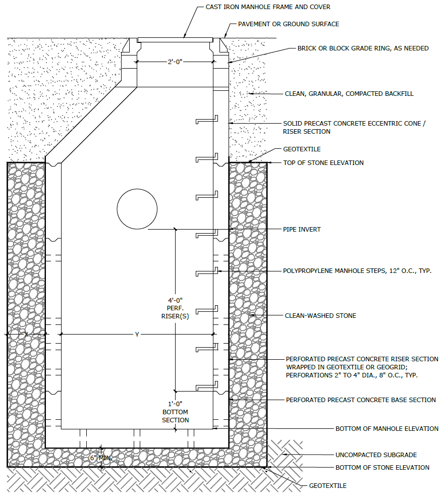
Figure 4.15‑3: Thermoplastic drainage well standard detail
(The designer is referred to Appendix L to download Standard Detail CAD files.)
4.15.4 Drainage well material standards
Pretreatment material standards
- The designer is referred to Section 4.10, Pretreatment, for information on materials standards for pretreatment systems.
Inlet control material standards
- The designer is referred to Section 4.11, Inlet Controls, for information on material standards for inlet control systems.
Storage area material standards
- Precast concrete drainage well manholes must meet the following specifications:
- Concrete risers: five‑inch thick, 4,000 psi concrete, 3×12 WWF (six gauge) reinforcement
- Base section: nine‑inch thick, 4,000 psi concrete, #4 rebar reinforcement, six inches on center
- Perforations: two to four‑inch diameter, eight inches on center
- Connections to be made with non-shrink grout
- Thermoplastic drainage well manholes must meet the following specifications:
- Thermoplastic well sections: PVC
- Perforations: one to two‑inch diameter, six inches on center
- Connections to be made with like materials per manufacturer recommendations
- Stone designed for stormwater storage must be uniformly graded, crushed, clean-washed stone. PWD defines “clean-washed” as having less than 0.5% wash loss, by mass, when tested per American Association of State Highway and Transportation Officials (AASHTO) T-11 wash loss test. AASHTO No. 3 and No. 57 stone can meet this specification.
- Geotextile, if used, must consist of polypropylene fibers and meet the following specifications (AASHTO Class 1 or Class 2 geotextile is recommended):
- Grab Tensile Strength (ASTM-D4632): ≥ 250 lbs
- CBR Puncture Strength (ASTM-D6241): ≥ 500 lbs
- Flow Rate (ASTM-D4491): ≥ 95 gal/min/ft2
- UV Resistance after 500 hrs (ASTM-D4355): ≥ 70%
- Tear Resistance (ASTM-D4533): ≥ 80 lbs
- Heat-set or heat-calendared fabrics are not permitted
- Geogrid, if used, must meet the following specifications:
- Maximum Apparent Opening Size (AOS): 0.25‑inch
- Grab Tensile Strength (ASTM-D4632): ≥ 205 lbs
- CBR Puncture Strength (ASTM-D6241): ≥ 500 lbs
- UV Resistance after 500 hrs (ASTM-D4355): ≥ 70%
- Tear Resistance (ASTM-D4533): ≥ 80 lbs
Outlet control material standards
- The designer is referred to Section 4.12, Outlet Controls, for information on material standards for outlet control systems.
Inspection and maintenance access material standards
- Manhole covers must allow access to drainage well.
4.15.5 Drainage well construction guidance
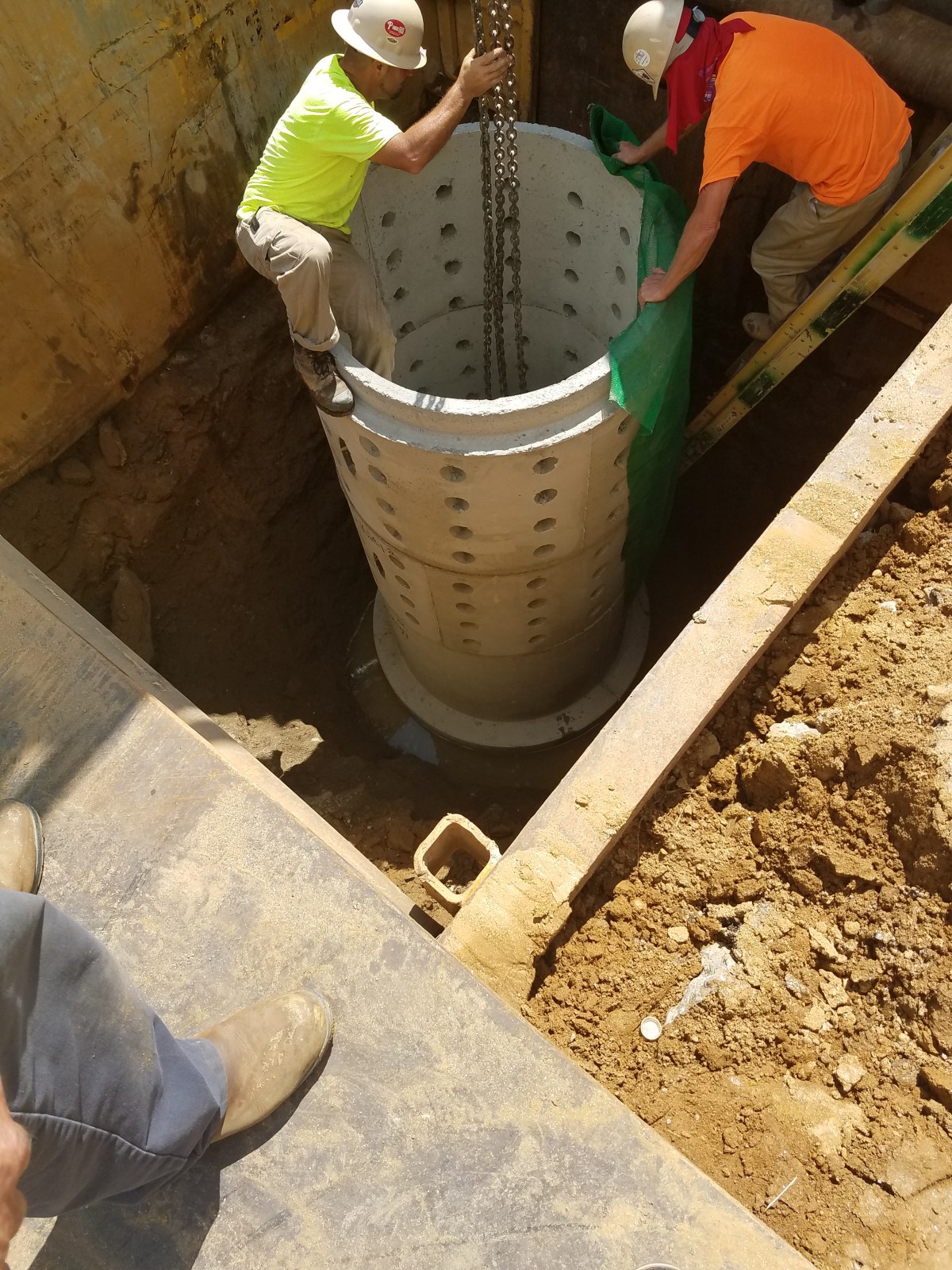
Proper construction and careful consideration of soil compaction, infiltration performance, and sedimentation control of drainage wells are essential to ensure long-term functionality and reduce long-term maintenance needs and costs. Construction oversight is critical. At a minimum, verification of volumes, grades, and elevations must be performed prior to backfill.
- If the contractor proposes to install deep drainage wells, especially if using drilled caissons, a Vibration Monitoring Plan is recommended. The contractor should monitor vibrations and stop work and reevaluate the proposed system with the Engineer if excessive vibrations are identified.
- Areas for proposed drainage wells must be physically marked as heavy equipment exclusion zones prior to any land-disturbing activities to avoid soil disturbance and compaction during construction. Install construction fencing around drainage well areas. If areas are compacted during construction, additional infiltration testing and potential redesign may be required.
- Provide erosion and sedimentation control protection on the site such that construction runoff is directed away from the proposed drainage well. Sediment deposited in a drainage well during construction, may significantly reduce SMP performance. The designer is referred to the latest edition of the Pennsylvania Department of Environmental Protection (PA DEP) Erosion and Sediment Pollution Control Program Manual for information on design standards for erosion and sedimentation control practices.
- Drainage well areas may not be used as sediment traps during construction, unless at least three feet of soil are left in place while the area is serving as a sediment trap and subsequently removed during construction after the contributing drainage areas have been stabilized.
- Complete site elevation grading and stabilize all disturbed soil. Stabilization of disturbed areas must be implemented before finalizing the drainage well’s excavation and construction.
- Excavate drainage well to proposed depth and manually grade and scarify the horizontal and vertical existing soil surfaces. The bottom of the drainage well footprint must be at a level grade.
- Existing subgrade must not be compacted or subject to excessive construction equipment prior to placement of geotextile and stone bed. The use of machinery to load stone from outside of the drainage well footprint is recommended. Stone should be carefully placed in the drainage well excavation. Should the subgrade be compacted during construction, additional testing of soil infiltration rates and SMP redesign may be required. Rock construction entrances must not be located on top of areas proposed for drainage wells.
- Place geotextile and stone immediately after approval of subgrade preparation to prevent accumulation of debris or sediment. Prevent runoff and sediment from entering the drainage well excavation during the placement of the geotextile and stone.
- Place geotextile in accordance with manufacturer’s standards and recommendations.
- Install bedding stone in lifts no greater than eight inches. Lightly compact each layer with equipment, keeping equipment movement over stone bedding material to a minimum. Install stone to grades indicated on the drawings.
- All stone that is used in the drainage well system must remain free of sediment. If sediment enters the stone, the contractor may be required to remove the sediment and replace with clean washed stone.
- Confirm and document invert elevations and dimensions of all structures such as connections and pipes prior to backfill.
- Backfill to finished grade. Ensure backfill is properly compacted in accordance with specifications. Ensure backfill process does not disrupt pipe placement and configuration.
- Structures such as inlet boxes, reinforced concrete boxes, inlet controls, and outlet controls must be constructed according to manufacturer’s guidelines or design professional’s guidance.
- Complete surface grading above and around drainage well, using suitable equipment to avoid excess compaction.
- Once the site is permanently stabilized with vegetation or hardscaping, remove temporary erosion and sediment control measures.
4.15.6 Drainage well maintenance guidance
Maintenance of drainage wells focuses on the periodic removal of sediment and debris from pretreatment and storage areas. Sediment removal from vaults, chambers, and pipes is typically conducted using vacuum or flushing systems. Considerations for inspection and maintenance equipment access to the drainage well and associated structures are critical to successful long-term maintenance. Guidance on the use and operation of vacuum or flushing sediment removal equipment is beyond the scope of this Manual; a maintenance professional should be contacted for additional details. As applicable, drainage well maintenance procedures must meet OSHA confined space entry requirements.
General recommended maintenance activities for drainage wells are summarized in Table 4.15‑1.
Table 4.15‑1: Drainage well maintenance guidelines
| Early maintenance activity | Frequency |
|---|---|
| Inspect erosion control and flow spreading devices until soil settlement and vegetative establishment of contributing areas has occurred. | Biweekly |
| Inspect inlet controls, outlet structures, and storage areas for trash and sediment accumulation. Remove debris and sediment as necessary. | Monthly for the first year after installation to determine ongoing maintenance frequency |
| Ongoing maintenance activity | Frequency |
|---|---|
| Regularly clean out gutters and catch basins to reduce sediment load to drainage well. Clean intermediate sump boxes, replace filters, and otherwise clean pretreatment areas in directly connected systems. | As needed |
| Remove sediment and debris from drainage well pretreatment sediment/grit chamber or separator, if applicable, when the sediment zone is 3/4 full. Sediment and debris build up may need to be removed by a professional. Consult with a professional as necessary. | As needed |
| Remove sediment and debris from drainage well when the sediment accumulates to three inches or more. | As needed |
| Replace filter bags for pretreatment devices. Please ensure filter bag is installed properly. | Quarterly |
| Inspect drainage well and control structures. | Quarterly |
| Remove floating debris and accumulated petroleum products from the system and all components. | Quarterly |
| Evaluate the drain down time of the drainage well after a storm of at least one inch to ensure a drain down time of less than 72 hours. | Ongoing |
| Maintain records of all inspections and maintenance activity. | Ongoing |
The designer is referred to Section 4.10, Pretreatment, Section 4.11, Inlet Controls, and Section 4.12, Outlet Controls, for information on maintenance guidance for pretreatment, inlet controls, and outlet controls.